EP0965247B1 - Multi-channel audio enhancement system for use in recording and playback and methods for providing same - Google Patents
Multi-channel audio enhancement system for use in recording and playback and methods for providing same Download PDFInfo
- Publication number
- EP0965247B1 EP0965247B1 EP97913930A EP97913930A EP0965247B1 EP 0965247 B1 EP0965247 B1 EP 0965247B1 EP 97913930 A EP97913930 A EP 97913930A EP 97913930 A EP97913930 A EP 97913930A EP 0965247 B1 EP0965247 B1 EP 0965247B1
- Authority
- EP
- European Patent Office
- Prior art keywords
- signals
- audio
- signal
- ambient
- channel
- Prior art date
- Legal status (The legal status is an assumption and is not a legal conclusion. Google has not performed a legal analysis and makes no representation as to the accuracy of the status listed.)
- Expired - Lifetime
Links
Images


Classifications
-
- H—ELECTRICITY
- H04—ELECTRIC COMMUNICATION TECHNIQUE
- H04S—STEREOPHONIC SYSTEMS
- H04S3/00—Systems employing more than two channels, e.g. quadraphonic
- H04S3/002—Non-adaptive circuits, e.g. manually adjustable or static, for enhancing the sound image or the spatial distribution
-
- H—ELECTRICITY
- H04—ELECTRIC COMMUNICATION TECHNIQUE
- H04S—STEREOPHONIC SYSTEMS
- H04S3/00—Systems employing more than two channels, e.g. quadraphonic
-
- H—ELECTRICITY
- H04—ELECTRIC COMMUNICATION TECHNIQUE
- H04S—STEREOPHONIC SYSTEMS
- H04S3/00—Systems employing more than two channels, e.g. quadraphonic
- H04S3/008—Systems employing more than two channels, e.g. quadraphonic in which the audio signals are in digital form, i.e. employing more than two discrete digital channels
-
- H—ELECTRICITY
- H04—ELECTRIC COMMUNICATION TECHNIQUE
- H04S—STEREOPHONIC SYSTEMS
- H04S2400/00—Details of stereophonic systems covered by H04S but not provided for in its groups
- H04S2400/01—Multi-channel, i.e. more than two input channels, sound reproduction with two speakers wherein the multi-channel information is substantially preserved
-
- H—ELECTRICITY
- H04—ELECTRIC COMMUNICATION TECHNIQUE
- H04S—STEREOPHONIC SYSTEMS
- H04S2420/00—Techniques used stereophonic systems covered by H04S but not provided for in its groups
- H04S2420/01—Enhancing the perception of the sound image or of the spatial distribution using head related transfer functions [HRTF's] or equivalents thereof, e.g. interaural time difference [ITD] or interaural level difference [ILD]
Definitions
- This invention relates generally to audio enhancement systems and a method for improving the realism and dramatic effects obtainable from two channel sound reproduction. More particularly, this invention relates to apparatus and a method for enhancing multiple audio signals and mixing these audio signals into a two channel format for reproduction in a conventional playback system.
- EP-A-637 191 discloses a surround signal processing apparatus which processes two-channel front stereophonic signals with a rear surround signal to produce two output signals.
- the apparatus processes the rear signal with a filter and then combines the filtered signal with the two-channel front stereophonic signals to generate two output signals.
- Audio recording and playback systems can be characterized by the number of individual channel or tracks used to input and/or play back a group of sounds.
- two channels each connected to a microphone may be used to record sounds detected from the distinct microphone locations.
- the sounds recording by the two channels are typically reproduced through a pair of loudspeakers, with one loudspeaker reproducing an individual channel.
- Providing two separate audio channels for recording permits individual processing of these channels to achieve an intended effect upon playback.
- providing more discrete audio channels allows more freedom in isolating certain sounds to enable the separate processing of these sounds.
- each sound recorded from an individual channel may be separately processed and played through a corresponding speaker or speakers.
- sounds which are recorded from, or intended to be placed at, multiple locations about a listener can be realistically reproduced through a dedicated speaker placed at the appropriate location.
- Such systems have found particular use in theaters and other audio-visual environments where a captive and fixed audience experiences both an audio and visual presentation.
- These systems which include Dolby Laboratories' "Dolby Digital” system; the Digital Theater System (DTS); and Sony's Dynamic Digital Sound (SDDS), are all designed to initially record and then reproduce multi-channel sounds to provide a surround listening experience.
- Dolby's AC-3 multi-channel encoding standard which provides six separate audio signals.
- two audio channels are intended for playback on forward left and right speakers, two channels are reproduced on rear left and right speakers, one channel is used for a forward center dialogue speaker, and one channel is used for low-frequency and effects signals.
- Audio playback systems which can accommodate the reproduction of all these six channels do not require that the signals be mixed into a two channel format.
- many playback systems including today's typical personal computer and tomorrow's personal computer/television, may have only two channel playback capability (excluding center and subwoofer channels). Accordingly, the information present in additional audio signals, apart from that of the conventional stereo signals, like those found in an AC-3 recording, must either be electronically discarded or mixed into a two channel format.
- a simple mixing method may be to simply combine all of the signals into a two-channel format while adjusting only the relative gains of the mixed signals.
- Other techniques may apply frequency shaping, amplitude adjustments, time delays or phase shifts, or some combination of all of these, to an individual audio signal during the final mixing process.
- the particular technique or techniques used may depend on the format and content of the individual audio signals as well as the intended use of the final two channel mix.
- U.S. Patent No. 4,393,270 issued to van den Berg discloses a method of processing electrical signals by modulating each individual signal corresponding to a preselected direction of perception which may compensate for placement of a loudspeaker.
- a separate multi-channel processing system is disclosed in U.S. Patent No. 5,438,623 issued to Begault. In Begault, individual audio signals are divided into two signals which are each delayed and filtered according to a head related transfer function (HRTF) for the left and right ears. The resultant signals are then combined to generate left and right output signals intended for playback through a set of headphones.
- HRTF head related transfer function
- an object of the present invention to provide an improved method of mixing multi-channel audio signals which can be used in all aspects of recording and playback to provide an improved and realistic listening experience. It is an object of the present invention to provide an improved system and method for mastering professional audio recordings intended for playback on a conventional stereo system. It is also an object of the present invention to provide a system and method to process multi-channel audio signals extracted from an audio-visual recording to provide an immersive listening experience when reproduced through a limited number of audio channels.
- An audio enhancement system and method for processing a group of audio signals, representing sounds existing in a 360 degree sound field, and combining the group of audio signals to create a pair of signals which can accurately represent the 360 degree sound field when played through a pair of speakers.
- the audio enhancement system can be used as a professional recording system or in personal computers and other home audio systems which include a limited amount of audio reproduction channels.
- a multi-channel recording provides multiple discrete audio signals consisting of at least a pair of left and right signals, a pair of surround signals, and a center channel signal.
- the home audio system is configured with speakers for reproducing two channels from a forward sound stage.
- the left and right signals and the surround signals are first processed and then mixed together to provide a pair of output signals for playback through the speakers.
- the left and right signals from the recording are processed collectively to provide a pair of spatially-corrected left and right signals to enhance sounds perceived by a listener as emanating from a forward sound stage.
- the surround signals are collectively processed by first isolating the ambient and monophonic components of the surround signals.
- the ambient and monophonic components of the surround signals are modified to achieve a desired spatial effect and to separately correct for positioning of the playback speakers.
- the surround signals are played through forward speakers as part of the composite output signals, the listener perceives the surround sounds as emanating from across the entire rear sound stage.
- the center signal may also be processed and mixed with the left, right and surround signals, or may be directed to a center channel speaker of the home reproduction system if one is present.
- a system processes at least four discrete audio signals including main left and right signals containing audio information intended for playback from a front sound stage, and surround left and right signals containing audio information intended for playback from a rear sound stage.
- the system generates a pair of left and right output signals for reproduction from the front sound stage to create the perception of a three dimensional sound image without the need for actual speakers placed in the rear sound stage.
- the system comprises a first electronic audio enhancer which receives the main left and right signals.
- the first audio enhancer processes an ambient component of the main left and right signals to create the perception of a broadened sound image across the front sound stage when the left and right output signals are reproduced by a pair of speakers positioned within the front sound stage.
- a second electronic audio enhancer receives the surround left and right signals.
- the second audio enhancer processes an ambient component of the surround left and right signals to create the perception of an acoustic sound image across the rear sound stage when the left and right output signals are reproduced by the pair of speakers positioned within the front sound stage.
- a third electronic audio enhancer which receives the surround left and right signals.
- the third audio enhancer processes a monophonic component of the surround left and right signals to create the perception of an acoustic sound image at a center location of the rear sound stage when the left and right output signals are reproduced by the pair of speakers positioned within the front sound stage.
- a signal mixer which generates the left and right output signals from the at least four discrete audio signals by combining the processed ambient component from the main left and right signals, the processed ambient component for the surround left and right signals, and the processed monophonic component from the surround left and right signals, wherein the ambient components of the main and surround signals are included in the left and right output signals in an out-of-phase relationship with respect to each other.
- the at least four discrete audio signals comprise a center channel signal containing audio information intended for playback by a front sound stage center speaker, and the center channel signal is combined by the signal mixer as part of the left and right output signals.
- the at least four discrete audio signals comprise a center channel signal containing audio information intended for playback by a center speaker located within the front sound stage, and the center channel signal is combined with a monophonic component of the main left and right signals by the signal mixer to generate the left and right output signals.
- the at least four discrete audio signals comprise a center channel signal having center stage audio information which is acoustically reproduced by a dedicated center channel speaker.
- the first, second, and third electronic audio enhancers apply an HRTF-based transfer function to a respective one of the discrete audio signals for creating an apparent sound image corresponding to the discrete audio signals when the left and right output signals are acoustically reproduced.
- the first audio enhancer equalizes the ambient component of the main left and right signals by boosting the ambient component below approximately 1 kHz and above approximately 2 kHz relative to frequencies between approximately 1 and 2 kHz.
- the peak gain applied to boost the ambient component, relative to the gain applied to the ambient component between approximately 1 and 2 kHz, is approximately 8 dB.
- the second and third audio enhancers equalize the ambient and monophonic components of the surround left and right signals by boosting the ambient and monophonic components below approximately 1 kHz and above approximately 2 kHz, relative to frequencies between approximately 1 and 2 kHz.
- the peak gain applied to boost the ambient and monophonic components of the surround left and right signals, relative to the gain applied to the ambient and monophonic components between approximately 1 and 2 kHz is approximately 18 dB.
- first, second, and third electronic audio enhancers are formed upon a semiconductor substrate. In yet another embodiment, the first, second, and third electronic audio enhancers are implemented in software.
- a multi-channel recording and playback apparatus receives a plurality of individual audio signals and processes the plurality of audio signals to provide first and second enhanced audio output signals for achieving an immersive sound experience upon playback of the output signals.
- the multi channel recording apparatus comprises a plurality of parallel audio signal processing devices for modifying the signal content of the individual audio signals wherein each parallel audio signal processing device comprises.
- a circuit receives two of the individual audio signals and isolates an ambient component of the two audio signals from a monophonic component of the two audio signals.
- a positional processing means which is capable of electronically applying a head related transfer function to each of the ambient and monophonic components of the two audio signals to generate processed ambient and monophonic components. The head related transfer functions corresponding to a desired spatial location with respect to a listener.
- a multi-channel circuit mixer combines the processed monophonic components and ambient components generated by the plurality of positional processing means to generate the enhanced audio output signals.
- the processed ambient components are then combined in an out-of-phase relationship with respect to the first and second output signals.
- each of the plurality of positional processing means further includes a circuit capable of individually modifying the two audio signals and wherein the multi-channel mixer further combines the two modified signals from the plurality of positional processing means with the respective ambient and monophonic components to generate the audio output signals.
- the circuit capable of individually modifying the two audio signals electronically applies, a head related transfer function to the two audio signals.
- the circuit capable of individually modifying the two audio signals electronically applies a time delay to one of the two audio signals.
- the two audio signals comprise audio information corresponding to a left front location and a right front location with respect to a listener.
- the two audio signals comprise audio information corresponding to a left rear location and a right rear location with respect to a listener.
- the plurality of parallel processing devices comprise first and second processing devices.
- the first processing device applies a head related transfer function to a first pair of the audio signals for achieving a first perceived direction for the first pair of audio signals when the output signals are reproduced.
- the second processing device applies a head related transfer function to a second pair of the audio signals for achieving a second perceived direction for the second pair of audio signals when the output signals are reproduced.
- the plurality of parallel audio processing devices and the multi-channel circuit mixer are implemented in a digital signal processing device of the multi-channel recording and playback apparatus.
- an audio enhancement system processes a plurality of audio source signals to create a pair of stereo output signals for generating a three dimensional sound field when the pair of stereo output signals are reproduced by a pair of loudspeakers.
- the audio enhancement system comprises a first processing circuit in communication with a first pair of the audio source signals.
- the first processing circuit is configured to isolate a first ambient component and a first monophonic component from the first pair of audio signals.
- the first processing circuit is further configured to modify the first ambient component and the first monophonic component to create a first acoustic image such that the first acoustic image is perceived by a listener as emanating from a first location.
- a second processing circuit which is in communication with a second pair of audio source signals.
- the second processing circuit is configured to isolate a second ambient component and a second monophonic component from the second pair of audio signals.
- the second processing circuit is further configured to modify the second ambient component and the second monophonic component to create a second acoustic image, such that the second acoustic image is perceived by the listener as emanating from a second location.
- a mixing circuit which is in communication with the first processing circuit and the second processing circuit.
- the mixing circuit is configured to combine the first and second modified monophonic components in phase and combine the first and second modified ambient components out of phase to generate a pair of stereo output signals.
- the first processing circuit is further configured to modify a plurality of frequency components in the first ambient component with a first transfer function.
- the first transfer function is further configured to emphasize a portion of the low frequency components in the first ambient component relative to other frequency components in the first ambient component.
- the first transfer function is configured to emphasize a portion of the high frequency components of the first ambient component relative to other frequency components in the first ambient component.
- the second processing circuit is configured to modify a plurality of frequency components in the second ambient component with a second transfer function.
- the second transfer function is configured to modify the frequency components in the second ambient component in a different manner than the first transfer function modifies the frequency components in the first ambient component.
- the second transfer function is configured to deemphasize a portion of the frequency components above approximately 11.5 kHz relative to other frequency components in the second ambient component. In yet another embodiment, the second transfer function is configured to deemphasize a portion of the frequency components between approximately 125 Hz and approximately 2.5 khz relative to other frequency components in the second ambient component. In yet another embodiment, the second transfer function is configured to increase a portion of the frequency components between approximately 2.5 khz and approximately 11.5 khz relative to other frequency components in the second ambient component.
- a multi-track audio processor receives a plurality of separate audio signals as part of a composite audio source.
- the plurality of audio signals comprise at least two distinct audio signal pairs which contain audio information which is desirably interpreted by a listener as emanating from distinct locations within a sound listening environment.
- the multi-track audio processor comprises a first electronic means which receives a first pair of the audio signals.
- the first electronic means separately applies a head related transfer function to an ambient component of the first pair of audio signals to create a first acoustic image wherein the first acoustic image is perceived by a listener as emanating from a first location.
- a second electronic means which receives a second pair of the audio signals.
- the second electronic means separately applies a head related transfer function to an ambient component and a monophonic component of the second pair of audio signals to create a second acoustic image wherein the second acoustic image is perceived by the listener as emanating from a second location.
- the means for mixing combines the ambient components out of phase to generate the pair of stereo output signals.
- an entertainment system has two main audio reproduction channels for reproducing an audio-visual recording to a user.
- the audio-visual recording comprises five discrete audio signals including a front-left signal, F L , a front-right signal, F R , a rear-left signal, R L , a rear-right signal, R R , and a center signal, C, and wherein the entertainment system achieves a surround sound experience for the user from the two main audio channels.
- the entertainment system comprising an audio-visual playback device for extracting the five discrete audio signals from the audio-visual recording.
- An audio processing device receives the five discrete audio signals and generates the two main audio reproduction channels.
- the audio processing device comprises a first processor for equalizing an ambient component of the front signals, F L and F R , to obtain a spatially-corrected ambient component (F L -F R ) P .
- a second processor equalizes an ambient component of the rear signals, R L and R R , to obtain a spatially-corrected ambient component (R L -R R ) P .
- a third processor equalizes a direct-field component of the rear signals, R L and R R , to obtain a spatially-corrected direct-field component (R L +R R ) P .
- a left mixer generates a left output signal.
- the left mixer combines the spatially-corrected ambient component, (F L -F R ) P , with the spatially-corrected ambient component, (R L -R R ) P , and the spatially-corrected direct-field component, (R L +R R ) P , to create the left output signal.
- a right mixer generates a right output signal.
- the right mixer combines an inverted spatially-corrected ambient component, (F R -F L ) P , with an inverted spatially-corrected ambient component, (R R -R L ) P , and the spatially-corrected direct-field component, (R L +R R ) P , to create the right output signal.
- a means reproduces the left and right output signals through the two main channels in connection with playback of the audio-visual recording to create a surround sound experience for the user.
- the center signal is input by the left mixer and combined as part of the left output signal and the center signal is combined by the right mixer and combined as part of the right output signal.
- the center signal and a direct field component of the front signals, F L +F R are combined by the left and right mixers as part of the left and right output signals, respectively.
- the center signal is provided as a third output signal for reproduction by a center channel speaker of the entertainment system.
- the entertainment system is a personal computer and the audio-visual playback device is a digital versatile disk (DVD) player.
- the entertainment system is a television and the audio-visual playback device is an associated digital versatile disk (DVD) player connected to the television system.
- the first, second, and third processors emphasize a low and high range of frequencies relative to a mid-range of frequencies.
- the audio processing device is implemented as an analog circuit formed upon a semiconductor substrate.
- the audio processing device is implemented in a software format, the software format executed by a microprocessor of the entertainment system.
- a method enhances a group of audio source signals wherein the audio source signals are designated for speakers placed around a listener to create left and right output signals for acoustic reproduction by a pair of speakers in order to simulate a surround sound environment.
- the audio source signals comprise a left-front signal (L F ), a right-front signal (R F ), a left-rear signal (L R ), and a right-rear signal (R R ).
- the method comprises an act of modifying the audio source signals to create processed audio signals based on the audio content of selected pairs of the source signals.
- the method further comprises an act of combining the processed audio signals with the audio source signals to create the left and right output signals.
- the transfer functions F1, F2, and F3 apply a level of equalization characterized by amplification of frequencies between approximately 50 and 500 Hz and between approximately 4 and 15 kHz relative to frequencies between approximately 500 Hz and 4 kHz.
- the left and right output signals further comprise a center channel audio source signal.
- the method is performed by a digital signal processing device.
- a method creates a simulated surround sound experience through reproduction of first and second output signals within an entertainment system having a source of at least four audio signals.
- the at least four audio source signals comprise a pair of front audio signals representing audio information emanating from a forward sound stage with respect to a listener, and a pair of rear audio signals representing audio information emanating from a rear sound stage with respect to the listener.
- the method comprises an act of combining the front audio signals to create a front ambient component signal and a front direct component signal.
- the method further comprises an act of combining the rear audio signals to create a rear ambient component signal and a rear direct component signal.
- the method further comprises an act of processing the front ambient component signal with a first HRTF-based transfer function to create a perceived source of direction of the front ambient component about a forward left and right aspect with respect to the listener.
- the method further comprises an act of processing the rear ambient component signal with a second HRTF-based transfer function to create a perceived source of direction of the rear ambient component about a rear left and right aspect with respect to the listener.
- the method further comprises an act of processing the rear direct component signal with a third HRTF-based transfer function to create a perceived source of direction of the rear direct component at a rear center aspect with respect to the listener.
- the method further comprises an act of combining a first one of the front audio signals, a first one of the rear audio signals, the processed front ambient component, the processed rear ambient component, and the processed rear direct component to create the first output signal.
- the method further comprises an act of combining a second one of the front audio signals, a second one of the rear audio signals, the processed front ambient component, processed rear ambient component, and the processed rear direct component to create the second output signal.
- the method further comprises an act of reproducing the first and second output signals, respectively, through a pair of speakers situated in the forward sound stage with respect to the listener.
- the first, second, and third HRTF-based transfer functions equalize a respective inputted through amplification of signal frequencies between approximately 50 and 500 Hz and between approximately 4 and 15 kHz relative to frequencies between approximately 500 Hz and 4 kHz.
- the entertainment system is a personal computer system and the at least four audio source signals are generated by a digital video disk player attached to the computer system.
- the entertainment system is a television and the at least four audio source signals are generated by an associated digital video disk player connected to the television system.
- the at least four audio signals comprise a center channel audio signal, the center channel signal electronically added to the first and second output signals.
- the act of processing with the first, second, and third HRTF-based transfer functions is performed by a digital signal processor.
- an audio enhancement device for use with an audio signal decoder provides multiple audio signals designated for playback through a group of speakers situated within a surround sound listening environment.
- the audio enhancement device generates, from the multiple audio signals, a pair of output signals for playback by a pair of speakers.
- the audio enhancement device comprises an enhancement apparatus for grouping a plurality of the multiple audio signals from the signal decoder into separate pairs of audio signals.
- the enhancement apparatus modifies each of the separate pairs of audio signals to generate separate pairs of component signals.
- a circuit combines the component signals to generate enhanced audio output signals, each of the enhanced audio output signals comprising a first component signal from a first pair of component signals and a second component signal from a second pair of component signals.
- an audio anhancement device for use with an audio signal decoder provides multiple audio signals designated for playback through a group of speakers situated within a surround sound listening environment.
- the audio enhancement device generates, from the multiple audio signals, a pair of output signals for playback by a pair of speakers.
- the audio enhancement device comprises a means for grouping at least some of the multiple audio signals of the signal decoder into separate pairs of audio signals.
- the means for grouping further including means for modifying each of the separate pairs of audio signals to generate separate pairs of component signals.
- the audio enhancement device further comprises a means for combining the component signals to generate enhanced audio output signals.
- Each of the enhanced audio output signals comprise a first component signal from a first pair of component signals and a second component signal from a second pair of component signals.
- FIG. 1 depicts a block diagram of a first preferred embodiment of a multi-channel audio enhancement system 10 for processing a group of audio signals and providing a pair of output signals.
- the audio enhancement system 10 comprises a source of multi-channel audio signal source 16 which outputs a group of discrete audio signals 18 to a multi-channel signal mixer 20.
- the mixer 20 provides a set of processed multi-channel outputs 22 to an audio immersion processor 24.
- the signal processor 24 provides a processed left channel signal 26 and a processed right channel signal 28 which can be directed to a recording device 30 or to a power amplifier 32 before reproduction by a pair of speakers 34 and 36.
- the signal mixer may also generate a bass audio signal 40 containing low-frequency information which corresponds to a bass signal, B, from the signal source 16, and/or a center audio signal 42 containing dialogue or other centrally located sounds which corresponds to a center signal, C, output from the signal source 16. Not all signal sources will provide a separate bass effects channel B, nor a center channel C, and therefore it is to be understood that these channels are shown as optional signal channels.
- the signals 40 and 42 are represented by the output signals 44 and 46, respectively.
- the audio enhancement system 10 of Figure 1 receives audio information from the audio source 16.
- the audio information may be in the form of discrete analog or digital channels or as a digital data bitstream.
- the audio source 16 may be signals generated from a group of microphones attached to various instruments in an orchestral or other audio performance.
- the audio source 16 may be a pre-recorded multi-track rendition of an audio work.
- the particular form of audio data received from the source 16 is not particularly relevant to the operation of the enhancement system 10.
- Figure 1 depicts the source audio signals as comprising eight main channels A 0 -A 7 , a single bass or low-frequency channel, B, and a single center channel signal, C. It can be appreciated by one of ordinary skill in the art that the concepts of the present invention are equally applicable to any multi-channel system of greater or fewer individual audio channels.
- the multi-channel immersion processor 24 modifies the output signals 22 received from the mixer 20 to create an immersive three-dimensional effect when a pair of output signals, L OUT and R OUT , are acoustically reproduced.
- the processor 24 is shown in Figure 1 as an analog processor operating in real time on the multi-channel mixed output signals 22. If the processor 24 is an analog device and if the audio source 16 provides a digital data output, then the processor 24 must of course include a digital-to-analog converter (not shown) before processing the signals 22.
- An audio enhancement system 50 comprising a digital audio source 52 which delivers audio information along a path 54 to a multi-channel digital audio decoder 56.
- the decoder 56 transmits multiple audio channel signals along a path 58.
- optional bass and center signals B and C may be generated by the decoder 56.
- Digital data signals 58, B, and C are transmitted to an audio immersion processor 60 operating digitally to enhance the received signals.
- the processor 60 generates a pair of enhanced digital signals 62 and 64 which are fed to a digital to analog converter 66.
- the signals B and C are fed to the converter 66.
- the resultant enhanced analog signals 68 and 70, corresponding to the low frequency and center information, are fed to the power amplifier 32.
- the enhanced analog left and right signals, 72, 74 are delivered to the amplifier 32.
- the left and right enhanced signals 72 and 74 may be diverted to a recording device 30 for storing the processed signals 72 and 74 directly on a recording medium such as magnetic tape or an optical disk. Once stored on recorded media, the processed audio information corresponding to signals 72 and 74 may be reproduced by a conventional stereo system without further enhancement processing to achieve the intended immersive effect described herein.
- the amplifier 32 delivers an amplified left output signal 80, L OUT , to the left speaker 34 and delivers an amplified right output signal 82, R OUT , to the right speaker 36. Also, an amplified bass effects signal 84, B OUT , is delivered to a sub-woofer 86. An amplified center signal 88, C OUT , may be delivered to an optional center speaker (not shown). For near field reproductions of the signals 80 and 82, i.e., where a listener is position close to and in between the speakers 34 and 36, use of a center speaker may not be necessary to achieve adequate localization of a center image. However, in far-field applications where listeners are positioned relatively far from the speakers 34 and 36, a center speaker can be used to fix a center image between the speaker 34 and 36.
- the combination consisting largely of the decoder 56 and the processor 60 is represented by the dashed line 90 which may be implemented in any number of different ways depending on a particular application, design constraints, or mere personal preference.
- the processing performed within the region 90 may be accomplished wholly within a digital signal processor (DSP), within software loaded into a computer's memory, or as part of a micro-processor's native signal processing capabilities such as that found in Intel's Pentium generation of micro-processors.
- DSP digital signal processor
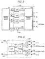
- the immersion processor 24 from Figure 1 is shown in association with the signal mixer 20.
- the processor 24 comprises individual enhancement modules 100, 102, and 104 which each receives a pair of audio signals from the mixer 20.
- the enhancement modules 100, 102, and 104 process a corresponding pair of signals on the stereo level in part by isolating ambient and monophonic components from each pair of signals. These components, along with the original signals are modified to generate resultant signals 108, 110, and 112. Bass, center and other signals which undergo individual processing are delivered along a path 118 to a module 116 which may provide level adjustment, simple filtering, or other modification of the received signals 118.
- the resultant signals 120 from the module 116, along with the signals 108, 110, and 112 are output to a mixer 124 within the processor 24.
- the module 100 consists of inputs 130 and 132 for receiving a pair of audio signals.
- the audio signals are transferred to a circuit or other processing means 134 for separating the ambient components from the direct field, or monophonic, sound components found in the input signals.
- the circuit 134 generates a direct sound component along a signal path 136 representing the summation signal M 1 +M 2 .
- a difference signal containing the ambient components of the input signals, M 1 -M 2 is transferred along a path 138.
- the sum signal M 1 +M 2 is modified by a circuit 140 having a transfer function F 1 .
- the difference signal M 1 -M 2 is modified by a circuit 142 having a transfer function F 2 .
- the transfer functions F 1 and F 2 may be identical and in a preferred embodiment provide spatial enhancement to the inputted signals by emphasizing certain frequencies while deemphasizing others.
- the transfer functions F 1 and F 2 may also apply HRTF-based processing to the inputted signals in order to achieve a perceived placement of the signals upon playback.
- the circuits 140 and 142 may be used to insert time delays or phase shifts of the input signals 136 and 138 with respect to the original signals M 1 and M 2 .
- the circuits 140 and 142 output a respective modified sum and difference signal, (M 1 +M 2 ) P and (M 1 -M 2 ) P , along paths 144 and 146, respectively.
- the original input signals M 1 and M 2 , as well as the processed signals (M 1 +M 2 ) P and (M 1 -M 2 ) P are fed to multipliers which adjust the gain of the received signals.
- the modified signals exit the enhancement module 100 at outputs 150, 152, 154, and 156.
- the output 150 delivers the signal K 1 M 1
- the output 152 delivers the signal K 2 F 1 (M 1 +M 2 )
- the output 154 delivers the signal K 3 F 4 (M 1 - M 2 )
- the output 156 delivers the signal K 4 M 2 , where K 1 -K 4 are constants determined by the setting of multipliers 148.
- the type of processing performed by the modules 100, 102, 104, and 116, and in particular the circuits 134, 140, and 142 may be user-adjustable to achieve a desired effect and/or a desired position of a reproduced sound. In some cases, it may be desirable to process only an ambient component or a monophonic component of a pair of input signals.
- the processing performed by each module may be distinct or it may be identical to one or more other modules.
- each module 100, 102, and 104 will generate four processed signals for receipt by the mixer 24 shown in Figure 3. All of the signals 108, 110, 112, and 120 may be selectively combined by the mixer 124 in accordance with principles common to one of ordinary skill in the art and dependent upon a user's preferences.
- Multi-channel signals at the stereo level i.e., in pairs
- subtle differences and similarities within the paired signals can be adjusted to achieve an immersive effect created upon playback through speakers.
- This immersive effect can be positioned by applying HRTF-based transfer functions to the processed signals to create a fully immersive positional sound field.
- Each pair of audio signals is separately processed to create a multi-channel audio mixing system that can effectively recreate the perception of a live 360 degree sound stage.
- HRTF processing of the components of a pair of audio signals e.g., the ambient and monophonic components
- more signal conditioning control is provided resulting in a more realistic immersive sound experience when the processed signals are acoustically reproduced.
- one particular application of the present invention is in audio playback devices which have the capability to process but not reproduce multi-channel audio signals.
- audio-visual recorded media are being encoded with multiple audio channel signals for reproduction in a home theater surround processing system.
- Such surround systems typically include forward or front speakers for reproducing left and right stereo signals, rear speakers for reproducing left surround and right surround signals, a center speaker for reproducing a center signal, and a subwoofer speaker for reproduction of a low-frequency signal.
- Recorded media which can be played by such surround systems may be encoded with multi-channel audio signals through such techniques as Dolby's proprietary AC-3 audio encoding standard.
- Many of today's playback devices are not equipped with surround or center channel speakers. As a consequence, the full capability of the multi-channel recorded media may be left untapped leaving the user with an inferior listening experience.
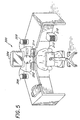
- a personal computer system 200 having an immersive positional audio processor constructed in accordance with the present invention.
- the computer system 200 consists of a processing unit 202 coupled to a display monitor 204.
- a front left speaker 206 and front right speaker 208, along with an optional sub-woofer speaker 210 are all connected to the unit 202 for reproducing audio signals generated by the unit 202.
- a listener 212 operates the computer system 200 via a keyboard 214.
- the computer system 200 processes a multi-channel audio signal to provide the listener 212 with an immersive 360 degree surround sound experience from just the speakers 206, 208 and the speaker 210 if available.
- the processing system disclosed herein will be described for use with Dolby AC-3 recorded media.
- the audio-visual playback device for reproducing the AC-3 recorded media may be a television, a combination television/personal computer, a digital video disk player coupled to a television, or any other device capable of playing a multi-channel audio recording.
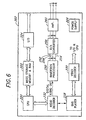
- FIG. 6 is a schematic block diagram of the major internal components of the processing unit 202 of Figure 5.
- the unit 202 contains the components of a typical personal computer system, constructed in accordance with principles common to one of ordinary skill, including a central processing unit (CPU) 220, a mass storage memory and a temporary random access memory (RAM) system 222, an input/output control device 224, all interconnected via an internal bus structure.
- the unit 202 also contains a power supply 226 and a recorded media player/recorder 228 which may be a DVD device or other multi-channel audio source.
- the DVD player 228 supplies video data to a video decoder 230 for display on a monitor.
- Audio data from the DVD player 228 is transferred to an audio decoder 232 which supplies multiple channel digital audio data from the player 228 to an immersion processor 250.
- the audio information from the decoder 232 contains a left front signal, a right front signal, a left surround signal, a right surround signal, a center signal, and a low-frequency signal, all of which are transferred to the immersion audio processor 250.
- the processor 250 digitally enhances the audio information from the decoder 232 in a manner suitable for playback with a conventional stereo playback system. Specifically, a left channel signal 252 and a right channel signal 254 are provided as outputs from the processor 250.
- a low-frequency sub-woofer signal 256 is also provided for delivery of bass response in a stereo playback system.
- the signals 252, 254, and 256 are first provided to a digital-to-analog converter 258, then to an amplifier 260, and then output for connection to corresponding speakers.
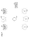
- FIG. 7 a schematic representation of speaker locations of the system of Figure 5 is shown from an overhead perspective.
- the listener 212 is positioned in front of and between the left front speaker 206 and the right front speaker 208.
- a simulated surround experience is created for the listener 212.
- ordinary playback of two channel signals through the speakers 206 and 208 will create a perceived phantom center speaker 214 from which monophonic components of left and right signals will appear to emanate.
- the left and right signals from an AC-3 six channel recording will produce the center phantom speaker 214 when reproduced through the speakers 206 and 208.
- the left and right surround channels of the AC-3 six channel recording are processed so that ambient surround sounds are perceived as emanating from rear phantom speakers 215 and 216 while monophonic surround sounds appear to emanate from a rear phantom center speaker 218. Furthermore, both the left and right front signals, and the left and right surround signals, are spatially enhanced to provide an immersive sound experience to eliminate the actual speakers 206, 208 and the phantom speakers 215, 216, and 218, as perceived point sources of sound. Finally, the low-frequency information is reproduced by an optional sub-woofer speaker 210 which may be placed at any location about the listener 212.
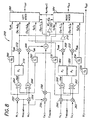
- FIG 8 is a schematic representation of an immersive processor and mixer for achieving a perceived immersive surround effect shown in Figure 7.
- the processor 250 corresponds to that shown in Figure 6 and receives six audio channel signals consisting of a front main left signal M L , a front main right signal M R , a left surround signal S L , a right surround signal S R , a center channel signal C, and a low-frequency effects signal B.
- the signals M L and M R are fed to corresponding gain-adjusting multipliers 252 and 254 which are controlled by a volume adjustment signal M volume .
- the gain of the center signal C may be adjusted by a first multiplier 256, controlled by the signal M volume , and a second multiplier 258 controlled by a center adjustment signal C volume .
- the surround signals S L and S R are first fed to respective multipliers 260 and 262 which are controlled by a volume adjustment signal S volume .
- the main front left and right signals, M L and M R are each fed to summing junctions 264 and 266.
- the summing junction 264 has an inverting input which receives M R and a non-inverting input which receives M L which combine to produce M L -M R along an output path 268.
- the signal M L -M R is fed to an enhancement circuit 270 which is characterized by a transfer function P 1 .
- a processed difference signal, (M L -M R ) P is delivered at an output of the circuit 270 to a gain adjusting multiplier 272.
- the output of the multiplier 272 is fed directly to a left mixer 280 and to an inverter 282.
- the inverted difference signal (M R -M L ) P is transmitted from the inverter 282 to a right mixer 284.
- a summation signal M L +M R exits the junction 266 and is fed to a gain adjusting multiplier 286.
- the output of the multiplier 286 is fed to a summing junction which adds the center channel signal, C, with the signal M L +M R .
- the combined signal, M L +M R +C exits the junction 290 and is directed to both the left mixer 280 and the right mixer 284.
- the original signals M L and M R are first fed through fixed gain adjustment circuits, i.e., amplifiers, 290 and 292, respectively, before transmission to the mixers 280 and 284.
- the surround left and right signals, S L and S R exit the multipliers 260 and 262, respectively, and are each fed to summing junctions 300 and 302.
- the summing junction 300 has an inverting input which receives S R and a non-inverting input which receives S L which combine to produce S L -S R along an output path 304.
- All of the summing junctions 264, 266, 300, and 302 may be configured as either an inverting amplifier or a non-inverting amplifier, depending on whether a sum or difference signal is generated. Both inverting and non-inverting amplifiers may be constructed from ordinary operational amplifiers in accordance with principles common to one of ordinary skill in the art.
- the signal S L -S R is fed to an enhancement circuit 306 which is characterized by a transfer function P 2 .
- a processed difference signal, (S L -S R ) P is delivered at an output of the circuit 306 to a gain adjusting multiplier 308.
- the output of the multiplier 308 is fed directly to the left mixer 280 and to an inverter 310.
- the inverted difference signal (S R -S L ) P is transmitted from the inverter 310 to the right mixer 284.
- a summation signal S L +S R exits the junction 302 and is fed to a separate enhancement circuit 320 which is characterized by a transfer function P 3 .
- a processed summation signal, (S L +S R ) P is delivered at an output of the circuit 320 to a gain adjusting multiplier 332. While reference is made to sum and difference signals, it should be noted that use of actual sum and difference signals is only representative. The same processing can be achieved regardless of how the ambient and monophonic components of a pair of signals are isolated.
- the output of the multiplier 332 is fed directly to the left mixer 280 and to the right mixer 284.
- the original signals S L and S R are first fed through fixed-gain amplifiers 330 and 334, respectively, before transmission to the mixers 280 and 284.
- the low-frequency effects channel, B is fed through an amplifier 336 to create the output low-frequency effects signal, B OUT .
- the low frequency channel, B may be mixed as part of the output signals, L OUT and R OUT , if no subwoofer is available.
- the enhancement circuit 250 of Figure 8 may be implemented in an analog discrete form, in a semiconductor substrate, through software run on a main or dedicated microprocessor, within a digital signal processing (DSP) chip, i.e., firmware, or in some other digital format. It is also possible to use a hybrid circuit structure combing both analog and digital components since in many cases the source signals will be digital. Accordingly, an individual amplifier, an equalizer, or other components, may be realized by software or firmware. Moreover, the enhancement circuit 270 of Figure 8, as well as the enhancement circuits 306 and 320, may employ a variety of audio enhancement techniques.
- DSP digital signal processing
- the circuit devices 270, 306, and 320 may use time-delay techniques, phase-shift techniques, signal equalization, or a combination of all of these techniques to achieve a desired audio effect.
- time-delay techniques phase-shift techniques
- signal equalization signal equalization
- a combination of all of these techniques may be used to achieve a desired audio effect.
- the basic principles of such audio enhancement techniques are common to one of ordinary skill in the art.
- the immersion processor circuit 250 uniquely conditions a set of AC-3 multi-channel signals to provide a surround sound experience through playback of the two output signals L OUT and R OUT .
- the signals M L and M R are processed collectively by isolating the ambient information present in these signals.
- the ambient signal component represents the differences between a pair of audio signals.
- An ambient signal component derived from a pair of audio signals is therefore often referred to as the "difference" signal component.
- the circuits 270, 306, and 320 are shown and described as generating sum and difference signals, other embodiments of audio enhancement circuits 270, 306, and 320 may not distinctly generate sum and difference signals at all. This can be accomplished in any number of ways using ordinary circuit design principles.
- the isolation of the difference signal information and its subsequent equalization may be performed digitally, or performed simultaneously at the input stage of an amplifier circuit.
- the ambient information of the front channel signals which can be represented by the difference M L -M R , is equalized by the circuit 270 according to the frequency response curve 350 of Figure 9.
- the curve 350 can be referred to as a spatial correction, or "perspective", curve.
- Such equalization of the ambient signal information broadens and blends a perceived sound stage generated from a pair of audio signals by selectively enhancing the sound information that provides a sense of spaciousness.
- the enhancement circuits 306 and 320 modify the ambient and monophonic components, respectively, of the surround signals S L and S R .
- the transfer functions P 2 and P 3 are equal and both apply the same level of perspective equalization to the corresponding input signal.
- the circuit 306 equalizes an ambient component of the surround signals, represented by the signal S L -S R
- the circuit 320 equalizes an monophonic component of the surround signals, represented by the signal S L +S R .
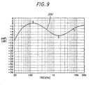
- the level of equalization is represented by the frequency response curve 352 of Figure 10.
- the perspective equalization curves 350 and 352 are displayed in Figures 9 and 10, respectively, as a function of gain, measured in decibels, against audible frequencies displayed in log format.
- the gain level in decibels at individual frequencies are only relevant as they relate to a reference signal since final amplification of the overall output signals occurs in the final mixing process.
- the perspective curve 350 has a peak gain at a point A located at approximately 125 Hz.
- the gain of the perspective curve 350 decreases above and below 125 Hz at a rate of approximately 6 dB per octave.
- the perspective curve 350 reaches a minimum gain at a point B within a range of approximately 1.5 - 2.5 kHz.
- the gain increases at frequencies above point B at a rate of approximately 6 dB per octave up to a point C at approximately 7 kHz, and then continues to increase up to approximately 20 kHz, i.e., approximately the highest frequency audible to the human ear.
- the perspective curve 352 has a peak gain at a point A located at approximately 125 Hz.
- the gain of the perspective curve 350 decreases below 125 Hz at a rate of approximately 6 dB per octave and decreases above 125 Hz at a rate of approximately 6 dB per octave.
- the perspective curve 352 reaches a minimum gain at a point B within a range of approximately 1.5 - 2.5 kHz.
- the gain increases at frequencies above point B at a rate of approximately 6 dB per octave up to a maximum-gain point C at approximately 10.5 - 11.5 kHz.
- the frequency response of the curve 352 decreases at frequencies above approximately 11.5 kHz.
- Apparatus and methods suitable for implementing the equalization curves 350 and 352 of Figures 9 and 10 are similar to those disclosed in pending application serial number 08/430751 filed on April 27, 1995 (US-A-5661808 published on 26.8.1997).
- Related audio enhancement techniques for enhancing ambient information are disclosed in U.S. Patent Nos. 4,738,669 and 4,866,774 issued to Arnold I. Klayman.
- the circuit 250 of Figure 8 uniquely functions to position the five main channel signals, M L , M R , C, S R , and S L about a listener upon reproduction by only two speakers.
- the curve 350 of Figure 9 applied to the signal M L -M R broadens and spatially enhances ambient sounds from the signals M L and M R . This creates the perception of a wide forward sound stage emanating from the speakers 206 and 208 shown in Figure 7. This is accomplished through selective equalization of the ambient signal information to emphasize the low and high frequency components.
- the equalization curve 352 of Figure 10 is applied to the signal S L -S R to broaden and spatially enhance the ambient sounds from the signals S L and S R .
- the equalization curve 352 modifies the signal S L -S R to account for HRTF positioning to obtain the perception of rear speakers 215 and 216 of Figure 7.
- the curve 352 contains a higher level of emphasis of the low and high frequency components of the signal S L -S R with respect to that applied to M L -M R . This is required since the normal frequency response of the human ear for sounds directed at a listener from zero degrees azimuth will emphasize sounds centered around approximately 2.75 kHz. The emphasis of these sounds results from the inherent transfer function of the average human pinna and from ear canal resonance.
- the perspective curve 352 of Figure 10 counteracts the inherent transfer function of the ear to create the perception of rear speakers for the signals S L -S R and S L +S R .
- the resultant processed difference signal (S L -S R ) P is driven out of phase to the corresponding mixers 280 and 284 to maintain the perception of a broad rear sound stage as if reproduced by phantom speakers 215 and 216.
- the present invention also recognizes that creation of a center rear phantom speaker 218, as shown in Figure 7, requires similar processing of the sum signal S L +S R since the sounds actually emanate from forward speakers 206 and 208. Accordingly, the signal S L +S R is also equalized by the circuit 320 according to the curve 352 of Figure 10. The resultant processed signal (S L +S R ) P is driven in-phase to achieve the perceived phantom speaker 218 as if the two phantom rear speakers 215 and 216 actually existed.
- the circuit 250 of Figure 8 can be modified so that the center signal C is fed directly to such center speaker instead of being mixed at the mixers 280 and 284.
- the approximate relative gain values of the various signals within the circuit 250 can be measured against a OdB reference for the difference signals exiting the multipliers 272 and 308.
- the gain of the amplifiers 290, 292, 330, and 334 in accordance with a preferred embodiment is approximately -18 dB
- the gain of the sum signal exiting the amplifier 332 is approximately -20 dB
- the gain of the sum signal exiting the amplifier 286 is approximately -20 dB
- the gain of the center channel signal exiting the amplifier 258 is approximately -7 dB.
- Adjustment of the multipliers 272, 286, 308, and 332 allows the processed signals to be tailored to the type of sound reproduced and tailored to a user's personal preferences.
- An increase in the level of a sum signal emphasizes the audio signals appearing at a center stage positioned between a pair of speakers.
- an increase in the level of a difference signal emphasizes the ambient sound information creating the perception of a wider sound image.
- the multipliers 272, 286, 308, and 332 may be preset and fixed at desired levels.
- multipliers 308 and 332 are desirably with the rear signal input levels, then it is possible to connect the enhancement circuits directly to the input signals S L and S R .
- the final ratio of individual signal strength for the various signals of Figure 8 is also affected by the volume adjustments and the level of mixing applied by the mixers 280 and 284.
- the enhanced output signals represented above may be magnetically or electronically stored on various recording media, such as vinyl records, compact discs, digital or analog audio tape, or computer data storage media. Enhanced audio output signals which have been stored may then be reproduced by a conventional stereo reproduction system to achieve the same level of stereo image enhancement.
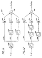
- FIG. 11 a schematic block diagram is shown of a circuit for implementing the equalization curve 350 of Figure 9 in accordance with a preferred embodiment.
- the circuit 270 inputs the ambient signal M L -M R , corresponding to that found at path 268 of Figure 8.
- the signal M L -M R is first conditioned by a high-pass filter 360 having a cutoff frequency, or -3dB frequency, of approximately 50 Hz. Use of the filter 360 is designed to avoid over-amplification of the bass components present in the signal M L -M R .
- the output of the filter 360 is split into three separate signal paths 362, 364, and 366 in order to spectrally shape the signal M L -M R .
- M L -M R is transmitted along the path 362 to an amplifier 368 and then on to a summing junction 378.
- the signal M L -M R is also transmitted along the path 364 to a low-pass filter 370, then to an amplifier 372, and finally to the summing junction 378.
- the signal M L -M R is transmitted along the path 366 to a high-pass filter 374, then to an amplifier 376, and then to the summing junction 378.
- the low-pass filter 370 has a cutoff frequency of approximately 200 Hz while the high-pass filter 374 has a cutoff frequency of approximately 7 kHz.
- the exact cutoff frequencies are not critical so long as the ambient components in a low and high frequency range, relative to those in a mid-frequency range of approximately 1 to 3 kHz, are amplified.
- the filters 360, 370, and 374 are all first order filters to reduce complexity and cost but may conceivably be higher order filters if the level of processing, represented in Figures 9 and 10, is not significantly altered.
- the amplifier 368 will have an approximate gain of one-half
- the amplifier 372 will have a gain of approximately 1.4
- the amplifier 376 will have an approximate gain of unity.
- the signals which exit the amplifiers 368, 372, and 376 make up the components of the signal (M L -M R ) P .
- the overall spectral shaping, i.e., normalization, of the ambient signal M L -M R occurs as the summing junction 378 combines these signals. It is the processed signal (M L -M R ) P which is mixed by the left mixer 280 (shown in Fig. 8) as part of the output signal L OUT . Similarly, the inverted signal (M R -M L ) P is mixed by the right mixer 284 (shown in Fig. 8) as part of the output signal R OUT .
- the gain separation between points A and 8 of the perspective curve 350 is ideally designed to be 9 dB, and the gain separation between points B and C should be approximately 6 dB.
- the gain of the amplifiers 368, 372, and 376 of Figure 11 are fixed, then the perspective curve 350 will remain constant. Adjustment of the amplifier 368 will tend to adjust the amplitude level of point B thus varying the gain separation between points A and B, and points B and C. In a surround sound environment, a gain separation much larger than 9 dB may tend to reduce a listener's perception of mid-range definition.
- FIG 12 a schematic block diagram is shown of a circuit for implementing the equalization curve 352 of Figure 10 in accordance with a preferred embodiment.
- the same curve 352 is used to shape the signals S L -S R and S L +S R , for ease of discussion purposes, reference is made in Figure 12 only to the circuit enhancement device 306.
- the characteristics of the device 306 is identical to that of 320.
- the circuit 306 inputs the ambient signal S L -S R , corresponding to that found at path 304 of Figure 8.
- the signal S L -S R is first conditioned by a high-pass filter 380 having a cutoff frequency of approximately 50 Hz.
- the output of the filter 380 is split into three separate signal paths 382, 384, and 386 in order to spectrally shape the signal S L -S R .
- the signal S L -S R is transmitted along the path 382 to an amplifier 388 and then on to a summing junction 396.
- the signal S L -S R is also transmitted along the path 384 to a high-pass filter 390 and then to a low-pass filter 392.
- the output of the filter 392 is transmitted to an amplifier 394, and finally to the summing junction 396.
- the signal S L -S R is transmitted along the path 386 to a low-pass filter 398, then to an amplifier 400, and then to the summing junction 396.
- each of the separately conditioned signals S L -S R are combined at the summing junction 396 to create the processed difference signal (S L -S R ) P ;
- the high-pass filter 370 has a cutoff frequency of approximately 21 kHz while the low-pass filter 392 has a cutoff frequency of approximately 8 kHz.
- the filter 392 serves to create the maximum-gain point C of Figure 10 and may be removed if desired.
- the low-pass filter 398 has a cutoff frequency of approximately 225 Hz.
- the exact number of filters and the cutoff frequencies are not critical so long as the signal S L -S R is equalized in accordance with Figure 10.
- all of the filters 380, 390, 392, and 398 are first order filters.
- the amplifier 388 will have an approximate gain of 0.1
- the amplifier 394 will have a gain of approximately 1.8
- the amplifier 400 will have an approximate gain of 0.8.
- the inverted signal (S R -S L ) P is mixed by the right mixer 284 (shown in Fig. 8) as part of the output signal R OUT .
- the gain separation between points A and B of the perspective curve 352 is ideally designed to be 18 dB, and the gain separation between points B and C should be approximately 10 dB.
- the gain of the amplifiers 388, 394, and 400 of Figure 12 are fixed, then the perspective curve 352 will remain constant. Adjustment of the amplifier 388 will tend to adjust the amplitude level of point B of the curve 352, thus varying the gain separation between points A and B, and points B and C.
Landscapes
- Engineering & Computer Science (AREA)
- Physics & Mathematics (AREA)
- Acoustics & Sound (AREA)
- Signal Processing (AREA)
- Multimedia (AREA)
- Stereophonic System (AREA)
- Management Or Editing Of Information On Record Carriers (AREA)
- Signal Processing For Digital Recording And Reproducing (AREA)
- Television Signal Processing For Recording (AREA)
Applications Claiming Priority (3)
| Application Number | Priority Date | Filing Date | Title |
|---|---|---|---|
| US743776 | 1996-11-07 | ||
| US08/743,776 US5912976A (en) | 1996-11-07 | 1996-11-07 | Multi-channel audio enhancement system for use in recording and playback and methods for providing same |
| PCT/US1997/019825 WO1998020709A1 (en) | 1996-11-07 | 1997-10-31 | Multi-channel audio enhancement system for use in recording and playback and methods for providing same |
Publications (2)
| Publication Number | Publication Date |
|---|---|
| EP0965247A1 EP0965247A1 (en) | 1999-12-22 |
| EP0965247B1 true EP0965247B1 (en) | 2002-08-14 |
Family
ID=24990122
Family Applications (1)
| Application Number | Title | Priority Date | Filing Date |
|---|---|---|---|
| EP97913930A Expired - Lifetime EP0965247B1 (en) | 1996-11-07 | 1997-10-31 | Multi-channel audio enhancement system for use in recording and playback and methods for providing same |
Country Status (13)
| Country | Link |
|---|---|
| US (4) | US5912976A (id) |
| EP (1) | EP0965247B1 (id) |
| JP (1) | JP4505058B2 (id) |
| KR (1) | KR100458021B1 (id) |
| CN (1) | CN1171503C (id) |
| AT (1) | ATE222444T1 (id) |
| AU (1) | AU5099298A (id) |
| CA (1) | CA2270664C (id) |
| DE (1) | DE69714782T2 (id) |
| ES (1) | ES2182052T3 (id) |
| ID (1) | ID18503A (id) |
| TW (1) | TW396713B (id) |
| WO (1) | WO1998020709A1 (id) |
Cited By (1)
| Publication number | Priority date | Publication date | Assignee | Title |
|---|---|---|---|---|
| WO2014130585A1 (en) * | 2013-02-19 | 2014-08-28 | Max Sound Corporation | Waveform resynthesis |
Families Citing this family (125)
| Publication number | Priority date | Publication date | Assignee | Title |
|---|---|---|---|---|
| US5912976A (en) * | 1996-11-07 | 1999-06-15 | Srs Labs, Inc. | Multi-channel audio enhancement system for use in recording and playback and methods for providing same |
| JP3788537B2 (ja) * | 1997-01-20 | 2006-06-21 | 松下電器産業株式会社 | 音響処理回路 |
| US6721425B1 (en) | 1997-02-07 | 2004-04-13 | Bose Corporation | Sound signal mixing |
| US6704421B1 (en) * | 1997-07-24 | 2004-03-09 | Ati Technologies, Inc. | Automatic multichannel equalization control system for a multimedia computer |
| US6459797B1 (en) * | 1998-04-01 | 2002-10-01 | International Business Machines Corporation | Audio mixer |
| EP1142443A1 (en) * | 1999-01-04 | 2001-10-10 | Britannia Investment Corporation | Loudspeaker mounting system comprising a flexible arm |
| US6442278B1 (en) * | 1999-06-15 | 2002-08-27 | Hearing Enhancement Company, Llc | Voice-to-remaining audio (VRA) interactive center channel downmix |
| KR100717251B1 (ko) * | 1999-07-20 | 2007-05-15 | 코닌클리케 필립스 일렉트로닉스 엔.브이. | 스테레오 신호와 데이터 신호를 보유한 기록매체 |
| US7031474B1 (en) | 1999-10-04 | 2006-04-18 | Srs Labs, Inc. | Acoustic correction apparatus |
| US7277767B2 (en) | 1999-12-10 | 2007-10-02 | Srs Labs, Inc. | System and method for enhanced streaming audio |
| US6351733B1 (en) | 2000-03-02 | 2002-02-26 | Hearing Enhancement Company, Llc | Method and apparatus for accommodating primary content audio and secondary content remaining audio capability in the digital audio production process |
| US7266501B2 (en) * | 2000-03-02 | 2007-09-04 | Akiba Electronics Institute Llc | Method and apparatus for accommodating primary content audio and secondary content remaining audio capability in the digital audio production process |
| US6684060B1 (en) * | 2000-04-11 | 2004-01-27 | Agere Systems Inc. | Digital wireless premises audio system and method of operation thereof |
| US7212872B1 (en) * | 2000-05-10 | 2007-05-01 | Dts, Inc. | Discrete multichannel audio with a backward compatible mix |
| US20040096065A1 (en) * | 2000-05-26 | 2004-05-20 | Vaudrey Michael A. | Voice-to-remaining audio (VRA) interactive center channel downmix |
| JP4304401B2 (ja) * | 2000-06-07 | 2009-07-29 | ソニー株式会社 | マルチチャンネルオーディオ再生装置 |
| US7369665B1 (en) | 2000-08-23 | 2008-05-06 | Nintendo Co., Ltd. | Method and apparatus for mixing sound signals |
| JP2002191099A (ja) * | 2000-09-26 | 2002-07-05 | Matsushita Electric Ind Co Ltd | 信号処理装置 |
| US6628585B1 (en) | 2000-10-13 | 2003-09-30 | Thomas Bamberg | Quadraphonic compact disc system |
| WO2002041668A2 (en) * | 2000-11-15 | 2002-05-23 | Mike Godfrey | A method of and apparatus for producing apparent multidimensional sound |
| US7644003B2 (en) * | 2001-05-04 | 2010-01-05 | Agere Systems Inc. | Cue-based audio coding/decoding |
| US7116787B2 (en) * | 2001-05-04 | 2006-10-03 | Agere Systems Inc. | Perceptual synthesis of auditory scenes |
| JP2003092761A (ja) * | 2001-09-18 | 2003-03-28 | Toshiba Corp | 動画再生装置、動画再生方法及び音声再生装置 |
| KR20040027015A (ko) * | 2002-09-27 | 2004-04-01 | (주)엑스파미디어 | 스트리밍시 오디오의 대역폭을 줄이기 위하여 몰입형오디오를 이용한 새로운 다운믹싱 기법 |
| FI118370B (fi) * | 2002-11-22 | 2007-10-15 | Nokia Corp | Stereolaajennusverkon ulostulon ekvalisointi |
| RU2315371C2 (ru) * | 2002-12-28 | 2008-01-20 | Самсунг Электроникс Ко., Лтд. | Способ и устройство для смешивания аудиопотока и носитель информации |
| KR20040060718A (ko) * | 2002-12-28 | 2004-07-06 | 삼성전자주식회사 | 오디오 스트림 믹싱 방법, 그 장치 및 그 정보저장매체 |
| US20040202332A1 (en) * | 2003-03-20 | 2004-10-14 | Yoshihisa Murohashi | Sound-field setting system |
| US6925186B2 (en) * | 2003-03-24 | 2005-08-02 | Todd Hamilton Bacon | Ambient sound audio system |
| US7518055B2 (en) * | 2007-03-01 | 2009-04-14 | Zartarian Michael G | System and method for intelligent equalization |
| US20050031117A1 (en) * | 2003-08-07 | 2005-02-10 | Tymphany Corporation | Audio reproduction system for telephony device |
| US7542815B1 (en) | 2003-09-04 | 2009-06-02 | Akita Blue, Inc. | Extraction of left/center/right information from two-channel stereo sources |
| US8054980B2 (en) | 2003-09-05 | 2011-11-08 | Stmicroelectronics Asia Pacific Pte, Ltd. | Apparatus and method for rendering audio information to virtualize speakers in an audio system |
| US6937737B2 (en) | 2003-10-27 | 2005-08-30 | Britannia Investment Corporation | Multi-channel audio surround sound from front located loudspeakers |
| US7522733B2 (en) * | 2003-12-12 | 2009-04-21 | Srs Labs, Inc. | Systems and methods of spatial image enhancement of a sound source |
| TW200522761A (en) * | 2003-12-25 | 2005-07-01 | Rohm Co Ltd | Audio device |
| US7394903B2 (en) * | 2004-01-20 | 2008-07-01 | Fraunhofer-Gesellschaft Zur Forderung Der Angewandten Forschung E.V. | Apparatus and method for constructing a multi-channel output signal or for generating a downmix signal |
| KR100620182B1 (ko) * | 2004-02-20 | 2006-09-01 | 엘지전자 주식회사 | 모션 데이터가 기록된 광디스크와 그에 따른 광디스크재생장치 및 방법 |
| US7805313B2 (en) * | 2004-03-04 | 2010-09-28 | Agere Systems Inc. | Frequency-based coding of channels in parametric multi-channel coding systems |
| JP2005352396A (ja) * | 2004-06-14 | 2005-12-22 | Matsushita Electric Ind Co Ltd | 音響信号符号化装置および音響信号復号装置 |
| WO2006011367A1 (ja) * | 2004-07-30 | 2006-02-02 | Matsushita Electric Industrial Co., Ltd. | オーディオ信号符号化装置および復号化装置 |
| KR100629513B1 (ko) * | 2004-09-20 | 2006-09-28 | 삼성전자주식회사 | 외부음향의 멀티 채널 변환이 가능한 광재생장치 및 그의광재생방법 |
| US20060078129A1 (en) * | 2004-09-29 | 2006-04-13 | Niro1.Com Inc. | Sound system with a speaker box having multiple speaker units |
| US7720230B2 (en) * | 2004-10-20 | 2010-05-18 | Agere Systems, Inc. | Individual channel shaping for BCC schemes and the like |
| US8204261B2 (en) * | 2004-10-20 | 2012-06-19 | Fraunhofer-Gesellschaft Zur Foerderung Der Angewandten Forschung E.V. | Diffuse sound shaping for BCC schemes and the like |
| EP1817767B1 (en) * | 2004-11-30 | 2015-11-11 | Agere Systems Inc. | Parametric coding of spatial audio with object-based side information |
| JP5017121B2 (ja) * | 2004-11-30 | 2012-09-05 | アギア システムズ インコーポレーテッド | 外部的に供給されるダウンミックスとの空間オーディオのパラメトリック・コーディングの同期化 |
| US7787631B2 (en) * | 2004-11-30 | 2010-08-31 | Agere Systems Inc. | Parametric coding of spatial audio with cues based on transmitted channels |
| TW200627999A (en) | 2005-01-05 | 2006-08-01 | Srs Labs Inc | Phase compensation techniques to adjust for speaker deficiencies |
| US7903824B2 (en) * | 2005-01-10 | 2011-03-08 | Agere Systems Inc. | Compact side information for parametric coding of spatial audio |
| WO2009002292A1 (en) * | 2005-01-25 | 2008-12-31 | Lau Ronnie C | Multiple channel system |
| EP1691348A1 (en) * | 2005-02-14 | 2006-08-16 | Ecole Polytechnique Federale De Lausanne | Parametric joint-coding of audio sources |
| US7184557B2 (en) | 2005-03-03 | 2007-02-27 | William Berson | Methods and apparatuses for recording and playing back audio signals |
| WO2006103875A1 (ja) * | 2005-03-28 | 2006-10-05 | Pioneer Corporation | Av機器操作システム |
| US7974417B2 (en) * | 2005-04-13 | 2011-07-05 | Wontak Kim | Multi-channel bass management |
| US7817812B2 (en) * | 2005-05-31 | 2010-10-19 | Polk Audio, Inc. | Compact audio reproduction system with large perceived acoustic size and image |
| US20070055510A1 (en) * | 2005-07-19 | 2007-03-08 | Johannes Hilpert | Concept for bridging the gap between parametric multi-channel audio coding and matrixed-surround multi-channel coding |
| TW200709035A (en) * | 2005-08-30 | 2007-03-01 | Realtek Semiconductor Corp | Audio processing device and method thereof |
| CA2621175C (en) * | 2005-09-13 | 2015-12-22 | Srs Labs, Inc. | Systems and methods for audio processing |
| JP4720405B2 (ja) * | 2005-09-27 | 2011-07-13 | 船井電機株式会社 | 音声信号処理装置 |
| TWI420918B (zh) * | 2005-12-02 | 2013-12-21 | Dolby Lab Licensing Corp | 低複雜度音訊矩陣解碼器 |
| ATE543343T1 (de) * | 2006-04-03 | 2012-02-15 | Srs Labs Inc | Tonsignalverarbeitung |
| ATE527833T1 (de) | 2006-05-04 | 2011-10-15 | Lg Electronics Inc | Verbesserung von stereo-audiosignalen mittels neuabmischung |
| WO2008006108A2 (en) * | 2006-07-07 | 2008-01-10 | Srs Labs, Inc. | Systems and methods for multi-dialog surround audio |
| KR101061132B1 (ko) * | 2006-09-14 | 2011-08-31 | 엘지전자 주식회사 | 다이알로그 증폭 기술 |
| JP5232791B2 (ja) | 2006-10-12 | 2013-07-10 | エルジー エレクトロニクス インコーポレイティド | ミックス信号処理装置及びその方法 |
| EP2082397B1 (en) * | 2006-10-16 | 2011-12-28 | Fraunhofer-Gesellschaft zur Förderung der angewandten Forschung e.V. | Apparatus and method for multi -channel parameter transformation |
| AU2007312598B2 (en) * | 2006-10-16 | 2011-01-20 | Dolby International Ab | Enhanced coding and parameter representation of multichannel downmixed object coding |
| WO2008060111A1 (en) | 2006-11-15 | 2008-05-22 | Lg Electronics Inc. | A method and an apparatus for decoding an audio signal |
| EP2102856A4 (en) | 2006-12-07 | 2010-01-13 | Lg Electronics Inc | METHOD AND DEVICE FOR PROCESSING AN AUDIO SIGNAL |
| US8265941B2 (en) | 2006-12-07 | 2012-09-11 | Lg Electronics Inc. | Method and an apparatus for decoding an audio signal |
| US8050434B1 (en) | 2006-12-21 | 2011-11-01 | Srs Labs, Inc. | Multi-channel audio enhancement system |
| US20080165976A1 (en) * | 2007-01-05 | 2008-07-10 | Altec Lansing Technologies, A Division Of Plantronics, Inc. | System and method for stereo sound field expansion |
| EP2122489B1 (en) * | 2007-03-09 | 2012-06-06 | Srs Labs, Inc. | Frequency-warped audio equalizer |
| US9015051B2 (en) * | 2007-03-21 | 2015-04-21 | Fraunhofer-Gesellschaft Zur Foerderung Der Angewandten Forschung E.V. | Reconstruction of audio channels with direction parameters indicating direction of origin |
| US8908873B2 (en) * | 2007-03-21 | 2014-12-09 | Fraunhofer-Gesellschaft Zur Foerderung Der Angewandten Forschung E.V. | Method and apparatus for conversion between multi-channel audio formats |
| JP5883561B2 (ja) * | 2007-10-17 | 2016-03-15 | フラウンホッファー−ゲゼルシャフト ツァ フェルダールング デァ アンゲヴァンテン フォアシュンク エー.ファオ | アップミックスを使用した音声符号器 |
| AU2008339211B2 (en) | 2007-12-18 | 2011-06-23 | Lg Electronics Inc. | A method and an apparatus for processing an audio signal |
| TWI475896B (zh) * | 2008-09-25 | 2015-03-01 | Dolby Lab Licensing Corp | 單音相容性及揚聲器相容性之立體聲濾波器 |
| UA101542C2 (ru) | 2008-12-15 | 2013-04-10 | Долби Лабораторис Лайсензин Корпорейшн | Виртуализатор окружающего звука с динамическим сжатием диапазона и способ |
| US20100260360A1 (en) * | 2009-04-14 | 2010-10-14 | Strubwerks Llc | Systems, methods, and apparatus for calibrating speakers for three-dimensional acoustical reproduction |
| GB2471089A (en) * | 2009-06-16 | 2010-12-22 | Focusrite Audio Engineering Ltd | Audio processing device using a library of virtual environment effects |
| WO2011044063A2 (en) * | 2009-10-05 | 2011-04-14 | Harman International Industries, Incorporated | Multichannel audio system having audio channel compensation |
| US8190438B1 (en) * | 2009-10-14 | 2012-05-29 | Google Inc. | Targeted audio in multi-dimensional space |
| KR101624904B1 (ko) | 2009-11-09 | 2016-05-27 | 삼성전자주식회사 | 휴대용 단말기에서 디엔엘에이를 이용하여 멀티 사운드 채널 컨텐츠를 재생하기 위한 장치 및 방법 |
| EP2630808B1 (en) | 2010-10-20 | 2019-01-02 | DTS, Inc. | Stereo image widening system |
| EP2464146A1 (en) | 2010-12-10 | 2012-06-13 | Fraunhofer-Gesellschaft zur Förderung der angewandten Forschung e.V. | Apparatus and method for decomposing an input signal using a pre-calculated reference curve |
| EP2661907B8 (en) | 2011-01-04 | 2019-08-14 | DTS, Inc. | Immersive audio rendering system |
| EP2523473A1 (en) * | 2011-05-11 | 2012-11-14 | Fraunhofer-Gesellschaft zur Förderung der angewandten Forschung e.V. | Apparatus and method for generating an output signal employing a decomposer |
| KR20120132342A (ko) * | 2011-05-25 | 2012-12-05 | 삼성전자주식회사 | 보컬 신호 제거 장치 및 방법 |
| JP5704013B2 (ja) * | 2011-08-02 | 2015-04-22 | ソニー株式会社 | ユーザ認証方法、ユーザ認証装置、およびプログラム |
| WO2013032822A2 (en) | 2011-08-26 | 2013-03-07 | Dts Llc | Audio adjustment system |
| KR101444140B1 (ko) * | 2012-06-20 | 2014-09-30 | 한국영상(주) | 모듈형 음향 시스템용 오디오 믹서 |
| US8737645B2 (en) | 2012-10-10 | 2014-05-27 | Archibald Doty | Increasing perceived signal strength using persistence of hearing characteristics |
| WO2014100554A1 (en) | 2012-12-20 | 2014-06-26 | Strubwerks Llc | Systems and methods for providing three dimensional enhanced audio |
| US9794715B2 (en) | 2013-03-13 | 2017-10-17 | Dts Llc | System and methods for processing stereo audio content |
| US9258664B2 (en) | 2013-05-23 | 2016-02-09 | Comhear, Inc. | Headphone audio enhancement system |
| US9036088B2 (en) | 2013-07-09 | 2015-05-19 | Archibald Doty | System and methods for increasing perceived signal strength based on persistence of perception |
| US9143107B2 (en) * | 2013-10-08 | 2015-09-22 | 2236008 Ontario Inc. | System and method for dynamically mixing audio signals |
| CN105917674B (zh) * | 2013-10-30 | 2019-11-22 | 华为技术有限公司 | 用于处理音频信号的方法和移动装置 |
| EP4421617A3 (en) | 2013-10-31 | 2024-11-06 | Dolby Laboratories Licensing Corporation | Binaural rendering for headphones using metadata processing |
| WO2015103470A1 (en) * | 2014-01-03 | 2015-07-09 | Fugoo Corporation | Portable stereo sound system |
| US9704491B2 (en) | 2014-02-11 | 2017-07-11 | Disney Enterprises, Inc. | Storytelling environment: distributed immersive audio soundscape |
| RU2571921C2 (ru) * | 2014-04-08 | 2015-12-27 | Общество с ограниченной ответственностью "МедиаНадзор" | Способ фильтрации бинауральных воздействий в аудиопотоках |
| CN109068260B (zh) * | 2014-05-21 | 2020-11-27 | 杜比国际公司 | 配置经由家庭音频回放系统的音频的回放的系统和方法 |
| US9782672B2 (en) | 2014-09-12 | 2017-10-10 | Voyetra Turtle Beach, Inc. | Gaming headset with enhanced off-screen awareness |
| US9774974B2 (en) * | 2014-09-24 | 2017-09-26 | Electronics And Telecommunications Research Institute | Audio metadata providing apparatus and method, and multichannel audio data playback apparatus and method to support dynamic format conversion |
| US10609475B2 (en) | 2014-12-05 | 2020-03-31 | Stages Llc | Active noise control and customized audio system |
| US9508335B2 (en) | 2014-12-05 | 2016-11-29 | Stages Pcs, Llc | Active noise control and customized audio system |
| US9654868B2 (en) | 2014-12-05 | 2017-05-16 | Stages Llc | Multi-channel multi-domain source identification and tracking |
| US10477334B2 (en) * | 2015-01-09 | 2019-11-12 | Setuo ANIYA | Method and apparatus for evaluating audio device, audio device and speaker device |
| KR102856247B1 (ko) * | 2015-06-17 | 2025-09-04 | 삼성전자주식회사 | 저연산 포맷 변환을 위한 인터널 채널 처리 방법 및 장치 |
| EP3312837A4 (en) * | 2015-06-17 | 2018-05-09 | Samsung Electronics Co., Ltd. | Method and device for processing internal channels for low complexity format conversion |
| US9934790B2 (en) * | 2015-07-31 | 2018-04-03 | Apple Inc. | Encoded audio metadata-based equalization |
| WO2017058097A1 (en) * | 2015-09-28 | 2017-04-06 | Razer (Asia-Pacific) Pte. Ltd. | Computers, methods for controlling a computer, and computer-readable media |
| US10206040B2 (en) * | 2015-10-30 | 2019-02-12 | Essential Products, Inc. | Microphone array for generating virtual sound field |
| US9864568B2 (en) * | 2015-12-02 | 2018-01-09 | David Lee Hinson | Sound generation for monitoring user interfaces |
| US9980075B1 (en) | 2016-11-18 | 2018-05-22 | Stages Llc | Audio source spatialization relative to orientation sensor and output |
| US9980042B1 (en) | 2016-11-18 | 2018-05-22 | Stages Llc | Beamformer direction of arrival and orientation analysis system |
| US10945080B2 (en) | 2016-11-18 | 2021-03-09 | Stages Llc | Audio analysis and processing system |
| EP3422738A1 (en) * | 2017-06-29 | 2019-01-02 | Nxp B.V. | Audio processor for vehicle comprising two modes of operation depending on rear seat occupation |
| US10306391B1 (en) * | 2017-12-18 | 2019-05-28 | Apple Inc. | Stereophonic to monophonic down-mixing |
| US12382234B2 (en) | 2020-06-11 | 2025-08-05 | Dolby Laboratories Licensing Corporation | Perceptual optimization of magnitude and phase for time-frequency and softmask source separation systems |
| US11924628B1 (en) * | 2020-12-09 | 2024-03-05 | Hear360 Inc | Virtual surround sound process for loudspeaker systems |
| US20250063316A1 (en) * | 2021-12-15 | 2025-02-20 | Atieva, Inc. | Signal processing approximating a standardized studio experience in a vehicle audio system having non-standard speaker locations |
Family Cites Families (136)
| Publication number | Priority date | Publication date | Assignee | Title |
|---|---|---|---|---|
| US3249696A (en) * | 1961-10-16 | 1966-05-03 | Zenith Radio Corp | Simplified extended stereo |
| US3229038A (en) * | 1961-10-31 | 1966-01-11 | Rca Corp | Sound signal transforming system |
| US3246081A (en) * | 1962-03-21 | 1966-04-12 | William C Edwards | Extended stereophonic systems |
| FI35014A (fi) * | 1962-12-13 | 1965-05-10 | Äänentoistojärjestelmä | |
| US3170991A (en) * | 1963-11-27 | 1965-02-23 | Glasgal Ralph | System for stereo separation ratio control, elimination of cross-talk and the like |
| JPS4312585Y1 (id) | 1965-12-17 | 1968-05-30 | ||
| US3892624A (en) * | 1970-02-03 | 1975-07-01 | Sony Corp | Stereophonic sound reproducing system |
| US3665105A (en) * | 1970-03-09 | 1972-05-23 | Univ Leland Stanford Junior | Method and apparatus for simulating location and movement of sound |
| US3757047A (en) * | 1970-05-21 | 1973-09-04 | Sansui Electric Co | Four channel sound reproduction system |
| CA942198A (en) * | 1970-09-15 | 1974-02-19 | Kazuho Ohta | Multidimensional stereophonic reproducing system |
| NL172815B (nl) * | 1971-04-13 | Sony Corp | Meervoudige geluidweergeefinrichting. | |
| US3761631A (en) * | 1971-05-17 | 1973-09-25 | Sansui Electric Co | Synthesized four channel sound using phase modulation techniques |
| US3697692A (en) * | 1971-06-10 | 1972-10-10 | Dynaco Inc | Two-channel,four-component stereophonic system |
| US3772479A (en) * | 1971-10-19 | 1973-11-13 | Motorola Inc | Gain modified multi-channel audio system |
| JPS5313962B2 (id) * | 1971-12-21 | 1978-05-13 | ||
| JPS4889702A (id) * | 1972-02-25 | 1973-11-22 | ||
| JPS5251764Y2 (id) * | 1972-10-13 | 1977-11-25 | ||
| GB1450533A (en) * | 1972-11-08 | 1976-09-22 | Ferrograph Co Ltd | Stereo sound reproducing apparatus |
| GB1522599A (en) * | 1974-11-16 | 1978-08-23 | Dolby Laboratories Inc | Centre channel derivation for stereophonic cinema sound |
| JPS51144202A (en) * | 1975-06-05 | 1976-12-11 | Sony Corp | Stereophonic sound reproduction process |
| JPS5229936A (en) * | 1975-08-30 | 1977-03-07 | Mitsubishi Heavy Ind Ltd | Grounding device for inhibiting charging current to the earth in distr ibution lines |
| GB1578854A (en) * | 1976-02-27 | 1980-11-12 | Victor Company Of Japan | Stereophonic sound reproduction system |
| JPS52125301A (en) * | 1976-04-13 | 1977-10-21 | Victor Co Of Japan Ltd | Signal processing circuit |
| US4063034A (en) * | 1976-05-10 | 1977-12-13 | Industrial Research Products, Inc. | Audio system with enhanced spatial effect |
| JPS5927692Y2 (ja) | 1976-11-08 | 1984-08-10 | カヤバ工業株式会社 | 農用トラクタの作業機及びアタツチメント用コントロ−ル弁 |
| JPS53114201U (id) * | 1977-02-18 | 1978-09-11 | ||
| US4209665A (en) * | 1977-08-29 | 1980-06-24 | Victor Company Of Japan, Limited | Audio signal translation for loudspeaker and headphone sound reproduction |
| JPS5832840B2 (ja) * | 1977-09-10 | 1983-07-15 | 日本ビクター株式会社 | 立体音場拡大装置 |
| JPS5458402U (id) | 1977-09-28 | 1979-04-23 | ||
| JPS5458402A (en) * | 1977-10-18 | 1979-05-11 | Torio Kk | Binaural signal corrector |
| NL7713076A (nl) * | 1977-11-28 | 1979-05-30 | Johannes Cornelis Maria Van De | Werkwijze en inrichting voor het opnemen van geluid en/of voor het bewerken van geluid voor- afgaande aan het weergeven daarvan. |
| US4237343A (en) * | 1978-02-09 | 1980-12-02 | Kurtin Stephen L | Digital delay/ambience processor |
| US4204092A (en) * | 1978-04-11 | 1980-05-20 | Bruney Paul F | Audio image recovery system |
| US4218583A (en) * | 1978-07-28 | 1980-08-19 | Bose Corporation | Varying loudspeaker spatial characteristics |
| US4332979A (en) * | 1978-12-19 | 1982-06-01 | Fischer Mark L | Electronic environmental acoustic simulator |
| US4239937A (en) * | 1979-01-02 | 1980-12-16 | Kampmann Frank S | Stereo separation control |
| US4218585A (en) * | 1979-04-05 | 1980-08-19 | Carver R W | Dimensional sound producing apparatus and method |
| US4309570A (en) * | 1979-04-05 | 1982-01-05 | Carver R W | Dimensional sound recording and apparatus and method for producing the same |
| US4303800A (en) * | 1979-05-24 | 1981-12-01 | Analog And Digital Systems, Inc. | Reproducing multichannel sound |
| JPS5931279B2 (ja) * | 1979-06-19 | 1984-08-01 | 日本ビクター株式会社 | 信号変換回路 |
| JPS56130400U (id) * | 1980-03-04 | 1981-10-03 | ||
| US4308423A (en) * | 1980-03-12 | 1981-12-29 | Cohen Joel M | Stereo image separation and perimeter enhancement |
| US4356349A (en) * | 1980-03-12 | 1982-10-26 | Trod Nossel Recording Studios, Inc. | Acoustic image enhancing method and apparatus |
| US4355203A (en) * | 1980-03-12 | 1982-10-19 | Cohen Joel M | Stereo image separation and perimeter enhancement |
| US4308424A (en) * | 1980-04-14 | 1981-12-29 | Bice Jr Robert G | Simulated stereo from a monaural source sound reproduction system |
| JPS56163685A (en) | 1980-05-21 | 1981-12-16 | Fukuda Ichikane | Knife |
| JPS575499A (en) * | 1980-06-12 | 1982-01-12 | Mitsubishi Electric Corp | Acoustic reproducing device |
| US4479235A (en) * | 1981-05-08 | 1984-10-23 | Rca Corporation | Switching arrangement for a stereophonic sound synthesizer |
| CA1206619A (en) * | 1982-01-29 | 1986-06-24 | Frank T. Check, Jr. | Electronic postage meter having redundant memory |
| JPS58144989U (ja) | 1982-03-19 | 1983-09-29 | クラリオン株式会社 | 音響機器 |
| AT379275B (de) * | 1982-04-20 | 1985-12-10 | Neutrik Ag | Stereophone wiedergabeanlage in fahrgastraeumen von kraftfahrzeugen |
| US4489432A (en) * | 1982-05-28 | 1984-12-18 | Polk Audio, Inc. | Method and apparatus for reproducing sound having a realistic ambient field and acoustic image |
| US4457012A (en) * | 1982-06-03 | 1984-06-26 | Carver R W | FM Stereo apparatus and method |
| US4495637A (en) * | 1982-07-23 | 1985-01-22 | Sci-Coustics, Inc. | Apparatus and method for enhanced psychoacoustic imagery using asymmetric cross-channel feed |
| JPS5927692A (ja) * | 1982-08-04 | 1984-02-14 | Seikosha Co Ltd | カラ−プリンタ |
| US4497064A (en) * | 1982-08-05 | 1985-01-29 | Polk Audio, Inc. | Method and apparatus for reproducing sound having an expanded acoustic image |
| US4567607A (en) * | 1983-05-03 | 1986-01-28 | Stereo Concepts, Inc. | Stereo image recovery |
| US4503554A (en) * | 1983-06-03 | 1985-03-05 | Dbx, Inc. | Stereophonic balance control system |
| DE3331352A1 (de) * | 1983-08-31 | 1985-03-14 | Blaupunkt-Werke Gmbh, 3200 Hildesheim | Schaltungsanordnung und verfahren fuer wahlweisen mono- und stereo-ton-betrieb von ton- und bildrundfunkemfaengern und -recordern |
| JPS60107998A (ja) * | 1983-11-16 | 1985-06-13 | Nissan Motor Co Ltd | 車両用音響装置 |
| US4589129A (en) * | 1984-02-21 | 1986-05-13 | Kintek, Inc. | Signal decoding system |
| US4594730A (en) * | 1984-04-18 | 1986-06-10 | Rosen Terry K | Apparatus and method for enhancing the perceived sound image of a sound signal by source localization |
| JPS60254995A (ja) * | 1984-05-31 | 1985-12-16 | Pioneer Electronic Corp | 車載用音場補正システム |
| JP2514141Y2 (ja) * | 1984-05-31 | 1996-10-16 | パイオニア株式会社 | 車載用音場補正装置 |
| US4569074A (en) * | 1984-06-01 | 1986-02-04 | Polk Audio, Inc. | Method and apparatus for reproducing sound having a realistic ambient field and acoustic image |
| JPS6133600A (ja) * | 1984-07-25 | 1986-02-17 | オムロン株式会社 | 車両速度規制標識制御システム |
| US4594610A (en) * | 1984-10-15 | 1986-06-10 | Rca Corporation | Camera zoom compensator for television stereo audio |
| JPS61166696A (ja) * | 1985-01-18 | 1986-07-28 | 株式会社東芝 | デジタル表示装置 |
| US4703502A (en) * | 1985-01-28 | 1987-10-27 | Nissan Motor Company, Limited | Stereo signal reproducing system |
| JPS61166696U (id) | 1985-04-04 | 1986-10-16 | ||
| US4696036A (en) * | 1985-09-12 | 1987-09-22 | Shure Brothers, Inc. | Directional enhancement circuit |
| US4748669A (en) * | 1986-03-27 | 1988-05-31 | Hughes Aircraft Company | Stereo enhancement system |
| GB2202074A (en) * | 1987-03-13 | 1988-09-14 | Lyons Clarinet Co Ltd | A musical instrument |
| NL8702200A (nl) * | 1987-09-16 | 1989-04-17 | Philips Nv | Werkwijze en een inrichting voor het instellen van de overdrachtskarakteristiek naar twee luisterposities in een ruimte |
| US4811325A (en) | 1987-10-15 | 1989-03-07 | Personics Corporation | High-speed reproduction facility for audio programs |
| JPH0744759B2 (ja) * | 1987-10-29 | 1995-05-15 | ヤマハ株式会社 | 音場制御装置 |
| US5144670A (en) * | 1987-12-09 | 1992-09-01 | Canon Kabushiki Kaisha | Sound output system |
| US4862502A (en) * | 1988-01-06 | 1989-08-29 | Lexicon, Inc. | Sound reproduction |
| CA1312369C (en) * | 1988-07-20 | 1993-01-05 | Tsutomu Ishikawa | Sound reproducer |
| JPH0720319B2 (ja) * | 1988-08-12 | 1995-03-06 | 三洋電機株式会社 | センターモードコントロール回路 |
| BG60225B2 (bg) * | 1988-09-02 | 1993-12-30 | Qsound Ltd. | Метод и устройство за формиране на звукови изображения |
| US5046097A (en) * | 1988-09-02 | 1991-09-03 | Qsound Ltd. | Sound imaging process |
| US5208860A (en) * | 1988-09-02 | 1993-05-04 | Qsound Ltd. | Sound imaging method and apparatus |
| US5105462A (en) * | 1989-08-28 | 1992-04-14 | Qsound Ltd. | Sound imaging method and apparatus |
| JP2522529B2 (ja) * | 1988-10-31 | 1996-08-07 | 株式会社東芝 | 音響効果装置 |
| US4866774A (en) * | 1988-11-02 | 1989-09-12 | Hughes Aircraft Company | Stero enhancement and directivity servo |
| DE3932858C2 (de) * | 1988-12-07 | 1996-12-19 | Onkyo Kk | Stereophonisches Wiedergabesystem |
| JPH0623119Y2 (ja) * | 1989-01-24 | 1994-06-15 | パイオニア株式会社 | サラウンド方式ステレオ再生装置 |
| US5146507A (en) * | 1989-02-23 | 1992-09-08 | Yamaha Corporation | Audio reproduction characteristics control device |
| US5172415A (en) | 1990-06-08 | 1992-12-15 | Fosgate James W | Surround processor |
| US5228085A (en) * | 1991-04-11 | 1993-07-13 | Bose Corporation | Perceived sound |
| US5325435A (en) * | 1991-06-12 | 1994-06-28 | Matsushita Electric Industrial Co., Ltd. | Sound field offset device |
| US5251260A (en) * | 1991-08-07 | 1993-10-05 | Hughes Aircraft Company | Audio surround system with stereo enhancement and directivity servos |
| US5255326A (en) | 1992-05-18 | 1993-10-19 | Alden Stevenson | Interactive audio control system |
| US5319713A (en) * | 1992-11-12 | 1994-06-07 | Rocktron Corporation | Multi dimensional sound circuit |
| AU3427393A (en) * | 1992-12-31 | 1994-08-15 | Desper Products, Inc. | Stereophonic manipulation apparatus and method for sound image enhancement |
| DE4302273C1 (de) * | 1993-01-28 | 1994-06-16 | Winfried Leibitz | Vorrichtung zum Züchten von Pilzen, insbesondere Champignons |
| US5572591A (en) * | 1993-03-09 | 1996-11-05 | Matsushita Electric Industrial Co., Ltd. | Sound field controller |
| JPH06269097A (ja) * | 1993-03-11 | 1994-09-22 | Sony Corp | 音響装置 |
| GB2277855B (en) * | 1993-05-06 | 1997-12-10 | S S Stereo P Limited | Audio signal reproducing apparatus |
| US5371799A (en) * | 1993-06-01 | 1994-12-06 | Qsound Labs, Inc. | Stereo headphone sound source localization system |
| US5400405A (en) * | 1993-07-02 | 1995-03-21 | Harman Electronics, Inc. | Audio image enhancement system |
| EP0637191B1 (en) * | 1993-07-30 | 2003-10-22 | Victor Company Of Japan, Ltd. | Surround signal processing apparatus |
| JP2947456B2 (ja) * | 1993-07-30 | 1999-09-13 | 日本ビクター株式会社 | サラウンド信号処理装置及び映像音声再生装置 |
| JP2982627B2 (ja) * | 1993-07-30 | 1999-11-29 | 日本ビクター株式会社 | サラウンド信号処理装置及び映像音声再生装置 |
| KR0135850B1 (ko) * | 1993-11-18 | 1998-05-15 | 김광호 | 음성재생장치 |
| DE69533973T2 (de) * | 1994-02-04 | 2005-06-09 | Matsushita Electric Industrial Co., Ltd., Kadoma | Schallfeldkontrollegerät und Kontrolleverfahren |
| JP2944424B2 (ja) * | 1994-06-16 | 1999-09-06 | 三洋電機株式会社 | 音響再生回路 |
| US5533129A (en) | 1994-08-24 | 1996-07-02 | Gefvert; Herbert I. | Multi-dimensional sound reproduction system |
| JP3276528B2 (ja) | 1994-08-24 | 2002-04-22 | シャープ株式会社 | 音像拡大装置 |
| JPH08265899A (ja) * | 1995-01-26 | 1996-10-11 | Victor Co Of Japan Ltd | サラウンド信号処理装置及び映像音声再生装置 |
| US5799094A (en) * | 1995-01-26 | 1998-08-25 | Victor Company Of Japan, Ltd. | Surround signal processing apparatus and video and audio signal reproducing apparatus |
| CA2170545C (en) * | 1995-03-01 | 1999-07-13 | Ikuichiro Kinoshita | Audio communication control unit |
| US5661808A (en) * | 1995-04-27 | 1997-08-26 | Srs Labs, Inc. | Stereo enhancement system |
| US5677957A (en) * | 1995-11-13 | 1997-10-14 | Hulsebus; Alan | Audio circuit producing enhanced ambience |
| US5771295A (en) * | 1995-12-26 | 1998-06-23 | Rocktron Corporation | 5-2-5 matrix system |
| US5970152A (en) * | 1996-04-30 | 1999-10-19 | Srs Labs, Inc. | Audio enhancement system for use in a surround sound environment |
| US5912976A (en) * | 1996-11-07 | 1999-06-15 | Srs Labs, Inc. | Multi-channel audio enhancement system for use in recording and playback and methods for providing same |
| US6009179A (en) * | 1997-01-24 | 1999-12-28 | Sony Corporation | Method and apparatus for electronically embedding directional cues in two channels of sound |
| US6721425B1 (en) * | 1997-02-07 | 2004-04-13 | Bose Corporation | Sound signal mixing |
| JP3663461B2 (ja) * | 1997-03-13 | 2005-06-22 | スリーエス テック カンパニー リミテッド | 周波数選択的空間感向上システム |
| US6236730B1 (en) | 1997-05-19 | 2001-05-22 | Qsound Labs, Inc. | Full sound enhancement using multi-input sound signals |
| US6175631B1 (en) | 1999-07-09 | 2001-01-16 | Stephen A. Davis | Method and apparatus for decorrelating audio signals |
| JP4029936B2 (ja) | 2000-03-29 | 2008-01-09 | 三洋電機株式会社 | 半導体装置の製造方法 |
| US7076071B2 (en) | 2000-06-12 | 2006-07-11 | Robert A. Katz | Process for enhancing the existing ambience, imaging, depth, clarity and spaciousness of sound recordings |
| US7254239B2 (en) * | 2001-02-09 | 2007-08-07 | Thx Ltd. | Sound system and method of sound reproduction |
| US6937737B2 (en) * | 2003-10-27 | 2005-08-30 | Britannia Investment Corporation | Multi-channel audio surround sound from front located loudspeakers |
| US7522733B2 (en) | 2003-12-12 | 2009-04-21 | Srs Labs, Inc. | Systems and methods of spatial image enhancement of a sound source |
| JP4312585B2 (ja) | 2003-12-12 | 2009-08-12 | 株式会社Adeka | 有機溶媒分散金属酸化物粒子の製造方法 |
| US7490044B2 (en) | 2004-06-08 | 2009-02-10 | Bose Corporation | Audio signal processing |
| US7853022B2 (en) | 2004-10-28 | 2010-12-14 | Thompson Jeffrey K | Audio spatial environment engine |
| WO2006054360A1 (ja) * | 2004-11-22 | 2006-05-26 | Mitsubishi Denki Kabushiki Kaisha | 音像生成装置及び音像生成プログラム |
| TW200627999A (en) * | 2005-01-05 | 2006-08-01 | Srs Labs Inc | Phase compensation techniques to adjust for speaker deficiencies |
| US9100765B2 (en) | 2006-05-05 | 2015-08-04 | Creative Technology Ltd | Audio enhancement module for portable media player |
| JP4835298B2 (ja) | 2006-07-21 | 2011-12-14 | ソニー株式会社 | オーディオ信号処理装置、オーディオ信号処理方法およびプログラム |
| US8577065B2 (en) | 2009-06-12 | 2013-11-05 | Conexant Systems, Inc. | Systems and methods for creating immersion surround sound and virtual speakers effects |
-
1996
- 1996-11-07 US US08/743,776 patent/US5912976A/en not_active Expired - Lifetime
-
1997
- 1997-10-31 KR KR10-1999-7004087A patent/KR100458021B1/ko not_active Expired - Lifetime
- 1997-10-31 CA CA002270664A patent/CA2270664C/en not_active Expired - Lifetime
- 1997-10-31 AT AT97913930T patent/ATE222444T1/de not_active IP Right Cessation
- 1997-10-31 EP EP97913930A patent/EP0965247B1/en not_active Expired - Lifetime
- 1997-10-31 ES ES97913930T patent/ES2182052T3/es not_active Expired - Lifetime
- 1997-10-31 JP JP52159398A patent/JP4505058B2/ja not_active Expired - Lifetime
- 1997-10-31 AU AU50992/98A patent/AU5099298A/en not_active Abandoned
- 1997-10-31 DE DE69714782T patent/DE69714782T2/de not_active Expired - Lifetime
- 1997-10-31 WO PCT/US1997/019825 patent/WO1998020709A1/en not_active Ceased
- 1997-11-05 TW TW086116501A patent/TW396713B/zh not_active IP Right Cessation
- 1997-11-07 CN CNB971262977A patent/CN1171503C/zh not_active Expired - Lifetime
- 1997-11-07 ID IDP973632A patent/ID18503A/id unknown
-
1999
- 1999-02-24 US US09/256,982 patent/US7200236B1/en not_active Expired - Fee Related
-
2007
- 2007-03-30 US US11/694,650 patent/US7492907B2/en not_active Expired - Fee Related
-
2009
- 2009-01-30 US US12/363,530 patent/US8472631B2/en not_active Expired - Fee Related
Cited By (1)
| Publication number | Priority date | Publication date | Assignee | Title |
|---|---|---|---|---|
| WO2014130585A1 (en) * | 2013-02-19 | 2014-08-28 | Max Sound Corporation | Waveform resynthesis |
Also Published As
| Publication number | Publication date |
|---|---|
| HK1011257A1 (en) | 1999-07-09 |
| KR20000053152A (ko) | 2000-08-25 |
| WO1998020709A1 (en) | 1998-05-14 |
| US7492907B2 (en) | 2009-02-17 |
| US5912976A (en) | 1999-06-15 |
| AU5099298A (en) | 1998-05-29 |
| CA2270664A1 (en) | 1998-05-14 |
| JP4505058B2 (ja) | 2010-07-14 |
| DE69714782T2 (de) | 2002-12-05 |
| JP2001503942A (ja) | 2001-03-21 |
| CN1171503C (zh) | 2004-10-13 |
| US7200236B1 (en) | 2007-04-03 |
| US20090190766A1 (en) | 2009-07-30 |
| CA2270664C (en) | 2006-04-25 |
| EP0965247A1 (en) | 1999-12-22 |
| CN1189081A (zh) | 1998-07-29 |
| TW396713B (en) | 2000-07-01 |
| ATE222444T1 (de) | 2002-08-15 |
| DE69714782D1 (de) | 2002-09-19 |
| ES2182052T3 (es) | 2003-03-01 |
| US20070165868A1 (en) | 2007-07-19 |
| US8472631B2 (en) | 2013-06-25 |
| KR100458021B1 (ko) | 2004-11-26 |
| ID18503A (id) | 1998-04-16 |
Similar Documents
| Publication | Publication Date | Title |
|---|---|---|
| EP0965247B1 (en) | Multi-channel audio enhancement system for use in recording and playback and methods for providing same | |
| US5970152A (en) | Audio enhancement system for use in a surround sound environment | |
| US7668317B2 (en) | Audio post processing in DVD, DTV and other audio visual products | |
| TWI489887B (zh) | 用於喇叭或耳機播放之虛擬音訊處理技術 | |
| US5610986A (en) | Linear-matrix audio-imaging system and image analyzer | |
| US6853732B2 (en) | Center channel enhancement of virtual sound images | |
| US5841879A (en) | Virtually positioned head mounted surround sound system | |
| US9154896B2 (en) | Audio spatialization and environment simulation | |
| EP3895451B1 (en) | Method and apparatus for processing a stereo signal | |
| JP2009141972A (ja) | 擬似立体音響出力をモノラル入力から合成する装置および方法 | |
| KR100677629B1 (ko) | 다채널 음향 신호에 대한 2채널 입체 음향 생성 방법 및장치 | |
| WO2002015637A1 (en) | Method and system for recording and reproduction of binaural sound | |
| WO2017165968A1 (en) | A system and method for creating three-dimensional binaural audio from stereo, mono and multichannel sound sources | |
| US9872121B1 (en) | Method and system of processing 5.1-channel signals for stereo replay using binaural corner impulse response | |
| JP2002291100A (ja) | オーディオ信号再生方法、及びパッケージメディア | |
| EP0323830B1 (en) | Surround-sound system | |
| WO2003061343A2 (en) | Surround-sound system | |
| AU751831C (en) | Method and system for recording and reproduction of binaural sound | |
| Toole | Direction and space–the final frontiers | |
| JPH03157100A (ja) | オーディオ信号再生装置 | |
| JP2003125500A (ja) | マルチチャンネル再生装置 | |
| HK1011257B (en) | Multi-channel audio enhancement system for use in recording and playback and methods for providing same |
Legal Events
| Date | Code | Title | Description |
|---|---|---|---|
| PUAI | Public reference made under article 153(3) epc to a published international application that has entered the european phase |
Free format text: ORIGINAL CODE: 0009012 |
|
| 17P | Request for examination filed |
Effective date: 19990525 |
|
| AK | Designated contracting states |
Kind code of ref document: A1 Designated state(s): AT BE CH DE DK ES FI FR GB GR IE IT LI LU MC NL PT SE |
|
| GRAG | Despatch of communication of intention to grant |
Free format text: ORIGINAL CODE: EPIDOS AGRA |
|
| 17Q | First examination report despatched |
Effective date: 20011029 |
|
| GRAG | Despatch of communication of intention to grant |
Free format text: ORIGINAL CODE: EPIDOS AGRA |
|
| GRAH | Despatch of communication of intention to grant a patent |
Free format text: ORIGINAL CODE: EPIDOS IGRA |
|
| GRAH | Despatch of communication of intention to grant a patent |
Free format text: ORIGINAL CODE: EPIDOS IGRA |
|
| GRAA | (expected) grant |
Free format text: ORIGINAL CODE: 0009210 |
|
| AK | Designated contracting states |
Kind code of ref document: B1 Designated state(s): AT BE CH DE DK ES FI FR GB GR IE IT LI LU MC NL PT SE |
|
| PG25 | Lapsed in a contracting state [announced via postgrant information from national office to epo] |
Ref country code: GR Free format text: LAPSE BECAUSE OF FAILURE TO SUBMIT A TRANSLATION OF THE DESCRIPTION OR TO PAY THE FEE WITHIN THE PRESCRIBED TIME-LIMIT Effective date: 20020814 Ref country code: FI Free format text: LAPSE BECAUSE OF FAILURE TO SUBMIT A TRANSLATION OF THE DESCRIPTION OR TO PAY THE FEE WITHIN THE PRESCRIBED TIME-LIMIT Effective date: 20020814 |
|
| REF | Corresponds to: |
Ref document number: 222444 Country of ref document: AT Date of ref document: 20020815 Kind code of ref document: T |
|
| REG | Reference to a national code |
Ref country code: GB Ref legal event code: FG4D |
|
| REG | Reference to a national code |
Ref country code: CH Ref legal event code: EP |
|
| REG | Reference to a national code |
Ref country code: IE Ref legal event code: FG4D |
|
| REF | Corresponds to: |
Ref document number: 69714782 Country of ref document: DE Date of ref document: 20020919 |
|
| REG | Reference to a national code |
Ref country code: CH Ref legal event code: NV Representative=s name: PATENTANWAELTE SCHAAD, BALASS, MENZL & PARTNER AG |
|
| PG25 | Lapsed in a contracting state [announced via postgrant information from national office to epo] |
Ref country code: LU Free format text: LAPSE BECAUSE OF NON-PAYMENT OF DUE FEES Effective date: 20021031 |
|
| PG25 | Lapsed in a contracting state [announced via postgrant information from national office to epo] |
Ref country code: DK Free format text: LAPSE BECAUSE OF FAILURE TO SUBMIT A TRANSLATION OF THE DESCRIPTION OR TO PAY THE FEE WITHIN THE PRESCRIBED TIME-LIMIT Effective date: 20021114 |
|
| PG25 | Lapsed in a contracting state [announced via postgrant information from national office to epo] |
Ref country code: PT Free format text: LAPSE BECAUSE OF FAILURE TO SUBMIT A TRANSLATION OF THE DESCRIPTION OR TO PAY THE FEE WITHIN THE PRESCRIBED TIME-LIMIT Effective date: 20021129 |
|
| ET | Fr: translation filed | ||
| REG | Reference to a national code |
Ref country code: ES Ref legal event code: FG2A Ref document number: 2182052 Country of ref document: ES Kind code of ref document: T3 |
|
| PG25 | Lapsed in a contracting state [announced via postgrant information from national office to epo] |
Ref country code: MC Free format text: LAPSE BECAUSE OF NON-PAYMENT OF DUE FEES Effective date: 20030501 |
|
| PLBE | No opposition filed within time limit |
Free format text: ORIGINAL CODE: 0009261 |
|
| STAA | Information on the status of an ep patent application or granted ep patent |
Free format text: STATUS: NO OPPOSITION FILED WITHIN TIME LIMIT |
|
| 26N | No opposition filed |
Effective date: 20030515 |
|
| PGFP | Annual fee paid to national office [announced via postgrant information from national office to epo] |
Ref country code: ES Payment date: 20091117 Year of fee payment: 13 Ref country code: CH Payment date: 20091014 Year of fee payment: 13 Ref country code: AT Payment date: 20091013 Year of fee payment: 13 |
|
| PGFP | Annual fee paid to national office [announced via postgrant information from national office to epo] |
Ref country code: IT Payment date: 20091022 Year of fee payment: 13 |
|
| REG | Reference to a national code |
Ref country code: CH Ref legal event code: PL |
|
| PG25 | Lapsed in a contracting state [announced via postgrant information from national office to epo] |
Ref country code: LI Free format text: LAPSE BECAUSE OF NON-PAYMENT OF DUE FEES Effective date: 20101031 Ref country code: CH Free format text: LAPSE BECAUSE OF NON-PAYMENT OF DUE FEES Effective date: 20101031 |
|
| PG25 | Lapsed in a contracting state [announced via postgrant information from national office to epo] |
Ref country code: AT Free format text: LAPSE BECAUSE OF NON-PAYMENT OF DUE FEES Effective date: 20101031 |
|
| REG | Reference to a national code |
Ref country code: ES Ref legal event code: FD2A Effective date: 20111121 |
|
| PG25 | Lapsed in a contracting state [announced via postgrant information from national office to epo] |
Ref country code: IT Free format text: LAPSE BECAUSE OF NON-PAYMENT OF DUE FEES Effective date: 20101031 |
|
| PG25 | Lapsed in a contracting state [announced via postgrant information from national office to epo] |
Ref country code: ES Free format text: LAPSE BECAUSE OF NON-PAYMENT OF DUE FEES Effective date: 20101101 |
|
| REG | Reference to a national code |
Ref country code: GB Ref legal event code: 732E Free format text: REGISTERED BETWEEN 20120913 AND 20120919 |
|
| REG | Reference to a national code |
Ref country code: FR Ref legal event code: TP Owner name: DTS LLC, US Effective date: 20121004 |
|
| REG | Reference to a national code |
Ref country code: DE Ref legal event code: R082 Ref document number: 69714782 Country of ref document: DE Representative=s name: VONNEMANN, KLOIBER & KOLLEGEN, DE |
|
| REG | Reference to a national code |
Ref country code: DE Ref legal event code: R082 Ref document number: 69714782 Country of ref document: DE Representative=s name: VKK PATENTANWAELTE, DE Effective date: 20121116 Ref country code: DE Ref legal event code: R082 Ref document number: 69714782 Country of ref document: DE Representative=s name: VONNEMANN, KLOIBER & KOLLEGEN, DE Effective date: 20121116 Ref country code: DE Ref legal event code: R081 Ref document number: 69714782 Country of ref document: DE Owner name: DTS LLC (N. D. GES. D. STAATES DELAWARE), CALA, US Free format text: FORMER OWNER: SRS LABS, INC., SANTA ANA, CALIF., US Effective date: 20121116 Ref country code: DE Ref legal event code: R081 Ref document number: 69714782 Country of ref document: DE Owner name: DTS LLC (N. D. GES. D. STAATES DELAWARE), US Free format text: FORMER OWNER: SRS LABS, INC., SANTA ANA, US Effective date: 20121116 |
|
| REG | Reference to a national code |
Ref country code: NL Ref legal event code: SD Effective date: 20130326 |
|
| REG | Reference to a national code |
Ref country code: FR Ref legal event code: PLFP Year of fee payment: 19 |
|
| REG | Reference to a national code |
Ref country code: FR Ref legal event code: PLFP Year of fee payment: 20 |
|
| PGFP | Annual fee paid to national office [announced via postgrant information from national office to epo] |
Ref country code: NL Payment date: 20161026 Year of fee payment: 20 Ref country code: FR Payment date: 20161025 Year of fee payment: 20 Ref country code: IE Payment date: 20161028 Year of fee payment: 20 Ref country code: GB Payment date: 20161027 Year of fee payment: 20 Ref country code: DE Payment date: 20161027 Year of fee payment: 20 |
|
| PGFP | Annual fee paid to national office [announced via postgrant information from national office to epo] |
Ref country code: BE Payment date: 20161027 Year of fee payment: 20 Ref country code: SE Payment date: 20161027 Year of fee payment: 20 |
|
| REG | Reference to a national code |
Ref country code: DE Ref legal event code: R071 Ref document number: 69714782 Country of ref document: DE |
|
| REG | Reference to a national code |
Ref country code: NL Ref legal event code: MK Effective date: 20171030 |
|
| REG | Reference to a national code |
Ref country code: GB Ref legal event code: PE20 Expiry date: 20171030 |
|
| REG | Reference to a national code |
Ref country code: IE Ref legal event code: MK9A |
|
| REG | Reference to a national code |
Ref country code: SE Ref legal event code: EUG |
|
| REG | Reference to a national code |
Ref country code: BE Ref legal event code: MK Effective date: 20171031 |
|
| PG25 | Lapsed in a contracting state [announced via postgrant information from national office to epo] |
Ref country code: IE Free format text: LAPSE BECAUSE OF EXPIRATION OF PROTECTION Effective date: 20171031 Ref country code: GB Free format text: LAPSE BECAUSE OF EXPIRATION OF PROTECTION Effective date: 20171030 |