EP0965251B1 - Procede et dispositif pour reguler le fonctionnement des lampes a decharge gazeuse - Google Patents
Procede et dispositif pour reguler le fonctionnement des lampes a decharge gazeuse Download PDFInfo
- Publication number
- EP0965251B1 EP0965251B1 EP98909447A EP98909447A EP0965251B1 EP 0965251 B1 EP0965251 B1 EP 0965251B1 EP 98909447 A EP98909447 A EP 98909447A EP 98909447 A EP98909447 A EP 98909447A EP 0965251 B1 EP0965251 B1 EP 0965251B1
- Authority
- EP
- European Patent Office
- Prior art keywords
- controller
- gas discharge
- value
- soll
- control unit
- Prior art date
- Legal status (The legal status is an assumption and is not a legal conclusion. Google has not performed a legal analysis and makes no representation as to the accuracy of the status listed.)
- Expired - Lifetime
Links
Images


Classifications
-
- H—ELECTRICITY
- H05—ELECTRIC TECHNIQUES NOT OTHERWISE PROVIDED FOR
- H05B—ELECTRIC HEATING; ELECTRIC LIGHT SOURCES NOT OTHERWISE PROVIDED FOR; CIRCUIT ARRANGEMENTS FOR ELECTRIC LIGHT SOURCES, IN GENERAL
- H05B41/00—Circuit arrangements or apparatus for igniting or operating discharge lamps
- H05B41/14—Circuit arrangements
- H05B41/36—Controlling
- H05B41/38—Controlling the intensity of light
- H05B41/39—Controlling the intensity of light continuously
- H05B41/392—Controlling the intensity of light continuously using semiconductor devices, e.g. thyristor
- H05B41/3921—Controlling the intensity of light continuously using semiconductor devices, e.g. thyristor with possibility of light intensity variations
-
- H—ELECTRICITY
- H05—ELECTRIC TECHNIQUES NOT OTHERWISE PROVIDED FOR
- H05B—ELECTRIC HEATING; ELECTRIC LIGHT SOURCES NOT OTHERWISE PROVIDED FOR; CIRCUIT ARRANGEMENTS FOR ELECTRIC LIGHT SOURCES, IN GENERAL
- H05B41/00—Circuit arrangements or apparatus for igniting or operating discharge lamps
- H05B41/14—Circuit arrangements
- H05B41/36—Controlling
- H05B41/38—Controlling the intensity of light
- H05B41/39—Controlling the intensity of light continuously
- H05B41/392—Controlling the intensity of light continuously using semiconductor devices, e.g. thyristor
- H05B41/3921—Controlling the intensity of light continuously using semiconductor devices, e.g. thyristor with possibility of light intensity variations
- H05B41/3925—Controlling the intensity of light continuously using semiconductor devices, e.g. thyristor with possibility of light intensity variations by frequency variation
-
- Y—GENERAL TAGGING OF NEW TECHNOLOGICAL DEVELOPMENTS; GENERAL TAGGING OF CROSS-SECTIONAL TECHNOLOGIES SPANNING OVER SEVERAL SECTIONS OF THE IPC; TECHNICAL SUBJECTS COVERED BY FORMER USPC CROSS-REFERENCE ART COLLECTIONS [XRACs] AND DIGESTS
- Y10—TECHNICAL SUBJECTS COVERED BY FORMER USPC
- Y10S—TECHNICAL SUBJECTS COVERED BY FORMER USPC CROSS-REFERENCE ART COLLECTIONS [XRACs] AND DIGESTS
- Y10S315/00—Electric lamp and discharge devices: systems
- Y10S315/04—Dimming circuit for fluorescent lamps
-
- Y—GENERAL TAGGING OF NEW TECHNOLOGICAL DEVELOPMENTS; GENERAL TAGGING OF CROSS-SECTIONAL TECHNOLOGIES SPANNING OVER SEVERAL SECTIONS OF THE IPC; TECHNICAL SUBJECTS COVERED BY FORMER USPC CROSS-REFERENCE ART COLLECTIONS [XRACs] AND DIGESTS
- Y10—TECHNICAL SUBJECTS COVERED BY FORMER USPC
- Y10S—TECHNICAL SUBJECTS COVERED BY FORMER USPC CROSS-REFERENCE ART COLLECTIONS [XRACs] AND DIGESTS
- Y10S315/00—Electric lamp and discharge devices: systems
- Y10S315/07—Starting and control circuits for gas discharge lamp using transistors
Definitions
- the present invention relates to a method for regulating the operating behavior of Gas discharge lamps according to the preamble of claim 1 and a device for operating gas discharge lamps, in particular an electronic ballast, according to the preamble of claim 3.
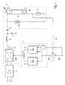
- Fig. 4 shows a known device according to the preamble of claim 3 Operation of gas discharge lamps.
- the device initially comprises a rectifier arrangement 4, the one Converts AC line voltage into a rectified DC link voltage an inverter 5 is supplied.
- the inverter 5 usually has two switches connected in series between a positive supply voltage and ground, which are controlled alternately.
- the connection point between the two alternately driven switches, usually through MOS field effect transistors are connected to a load circuit which is essentially one Series resonance circuit with a coil 6 and a capacitor 7 and at least one Gas discharge lamp 10 includes.
- the gas discharge lamp 10 is a Coupling capacitor 8 connected to the series resonant circuit.
- a heating transformer 9A-C is also present in FIG Primary winding 9A connected to the series resonant circuit and essentially in parallel is connected to the gas discharge lamp 10 and its secondary windings 9B and 9C each connected in parallel to one of the two lamp filaments of the gas discharge lamp 10 are.
- the heating transformer 9A-C serves to preheat the lamp filaments Gas discharge lamp 10, wherein the heating voltage has a frequency that is clear is below or above the resonance frequency. In this way it is avoided that the gas discharge lamp 10 ignites with cold lamp filaments, thereby increasing the service life the gas discharge lamp 10 can be extended.
- a heating capacitor can also be connected in parallel with the gas discharge lamp 10 his.
- gas discharge lamp 10 connected secondary windings 9B and 9C have the advantage that the lamp filaments even after the gas discharge lamp 10 has been ignited energy can still be supplied.
- the series resonance circuit with the coil 6 and the capacitor 7 and the Gas discharge lamp 10 are part of a controlled system 2, which in turn is part is a control loop, the behavior of which is determined by a controller 1.
- 4 serves to regulate the brightness of the Gas discharge lamp 10 as a function of an externally specified dimming setpoint SHOULD, which is in a comparator 3 designed as an adder with an actual dimming value is compared, the resulting difference signal DIFF to controller 1 is supplied, which, depending on the control difference DIFF, a control signal STELL for generates a certain controlled variable of the controlled system 2.
- it can Control signal, the frequency and / or the pulse duty factor of the inverter 5 supplied clocked AC voltage concern.
- the basic structure of the ballast shown in FIG. 4 is, for example already known from DE 40 18 127 A1. It suggests the actual value of a Operating size of the electronic ballast to record the difference between to form the detected actual value and a predetermined target value and this difference value to a controller, which is a control value depending on the difference value for example for the AC voltage of the series resonance circuit Generated in this way, the lamp brightness of the over the Series resonance circuit controlled gas discharge lamp.
- the controlled system 2 essentially has a PT 2 behavior, ie the controlled system 2 acts as a second-order delay element.
- a PID controller is advantageously used, ie a controller which has both proportionally amplifying and integrating and differentiating properties.
- a PI controller is generally used as controller 1 for the controlled system 2 shown in FIG. 4 for the sake of simplicity.
- This manipulated variable is fed to the limiter, which limits the manipulated value with respect to an adjustable maximum value, the Maximum value of the limiter is set depending on the specified setpoint. In particular, when the setpoint is low, the maximum value of the limiter decreased.
- EP-A1-0 605 052 describes a control method or an electronic ballast according to the preamble of claims 1 and 3, respectively.
- a control circuit compares that occurring in the load circuit of the electronic ballast Lamp current with a specifiable setpoint and generated depending on the difference a control signal for the between the actual value of the lamp current and the setpoint Frequency of the inverter.
- the control circuit has to avoid The control behavior of a PI controller.
- DE-A1-44 12 510 describes a lighting control circuit with a Feedback loop with a switchable only during the start-up phase Response speed.
- the response speed depends on the Lamp spinning with the luminous efficiency of the corresponding gas discharge lamp is correlated, switched.
- EP-A1-774 885 was published on 25/10/1996 with a Priority filed on 07/11/1995, and has been published on 21/01/1997. This document therefore belongs to the state of the art according to Article 54 (3) EPC.
- EP-A1-774 885 discloses a regulator device with a regulation range (i.e. with a proportional component) that have a high Value when the lighting reading is low is at a lower value if the Illumination measured value is high, is switched.
- the present invention has for its object a method and a Device for regulating the operating behavior of gas discharge lamps under To use a regulator with a proportional component, the regulation can be better adapted to the needs.
- the gas discharge lamps should also have a high degree of dimming, i.e. low lamp brightness, can be reliably ignited without lower Degrees of dimming, i.e. larger lamp powers, instabilities occur.
- the control loop Predefined setpoint for example the dimming setpoint
- the proportional component i.e. the Gain factor of the controller set and adjusted. So is for a start from Gas discharge lamps with low brightness values, i.e. high degrees of dimming, high Proportional share, i.e. a high gain factor is necessary in order to To be able to ignite a gas discharge lamp without flashing light.
- the proportional part of the Controller With increasing brightness the Gas discharge lamp, i.e. with decreasing dimming level, the proportional part of the Controller reduced and in extreme cases even set to zero, in which case the Controller works as a pure I controller. By reducing the proportional part of the controller with increasing lamp brightness, instabilities in the control loop itself become large lamp powers or lamp currents avoided.
- the aim is, therefore, for each individual load case
- a change from Operating state parameters of the control loop can be detected and specified select and set the ideal proportional component.
- the inventive method and electronic ballast takes place in particular wherever lighting with low brightness, i.e. high Degrees of dimming is desired, such as in movie theaters or the like, because According to the invention, ignition of gas discharge lamps even at a low level Degree of brightness without flash of light is reliably possible.
- Fig. 1 shows a first embodiment of the electronic according to the invention Ballast for operating gas discharge lamps.
- the electronic ballast shown in FIG. 1 has - as already with reference to FIG. 4 explained - a control loop on a controller 1, a controlled system 2 and one Comparator 3 includes.
- the components corresponding to those shown in FIG. 4 Components are provided with identical reference numerals, with a repeated one Description of these components is omitted.
- the embodiment of the electronic ballast according to the invention shown in FIG. 1 differs from the known electronic ballast shown in FIG. 4 mainly in the design of the regulator 1.
- the regulator 1 used in the electronic ballast according to the invention is also designed as a PI controller, which thus has a proportionally amplifying and integrating behavior.
- the PI controller 1 can advantageously be supplemented by a differentiating element, so that the PI controller becomes a PID controller which, although more complex, is more suitable for regulating the behavior of the controlled system which has a PT 2 behavior is.
- the externally specified dimming setpoint can be from an external dimmer or for example, also from a light sensor that detects a specific one from the lamp 10 monitored illuminated workplace.
- the PI controller 1 has an adjusting device 16 on, which could optionally be arranged outside of the PI controller 1.
- the setting device 16 is supplied with the externally predetermined dimming setpoint SOLL.
- the Adjustment device 16 sets depending on the dimming setpoint TARGET Proportional proportion of the PI element 14 of the PI controller 1.
- the dimming setpoint SH shall be compared in a comparator 3 with the actual dimming value ACTUAL, the result of which resulting difference value DIFF in addition to the P-element 14 and an I-element 13 of the PI controller 1 is supplied.
- the P control element 14 and the I control element 13 each generate depending a corresponding manipulated value from the difference value supplied, the thus generated control values are added on the output side by an adder 15 and as Control signal STELL of PI controller 1 are output.
- the detection of the actual value of the lamp brightness 10, i.e. the degree of dimming in particular - as already explained with reference to FIG. 4 - by determining the on a Resistor 12 dropping voltage, which is in series with the lower lamp filament Gas discharge lamp 10 is connected to ground.
- the on this resistor 12 falling voltage is a measure of the over the gas discharge path of the Gas discharge lamp 10 flowing lamp current with increasing lamp brightness increases.
- the setting of the P component within the PI controller 1 using the setting device 16 takes place depending on the predetermined dimming setpoint SHOULD as in Fig. 2a or 2b shown.
- the invention In order to reliably ignite the gas discharge lamp 10 even at low brightness values, i.e. at high dimming levels, without generating a flash of light in the To be able to ensure gas discharge lamp 10, the invention must Large proportion within the PI controller for such low brightness values to get voted. However, this high proportion or gain factor would even with large brightness values, i.e. low degrees of dimming are maintained, it could be due to the high flow in the controlled system 2 in this case Lamp current or the high lamp power to instabilities in the control loop. For this reason, with increasing lamp current, i.e. with increasing Lamp brightness, the proportional portion, i.e.
- the Adjustment device 16 depends on the dimming setpoint SHOULD applied to it Proportional portion of the proportional control element 14 according to that in FIGS. 2a and 2b shown characteristic.
- 2c shows curves of the lamp resistance R L of the lamp current I L corresponding to the characteristics of FIGS. 2a and 2b, depending on the lamp brightness of the gas discharge lamp 10 or the predetermined dimming setpoint SHOULD.
- 2c and 2d in particular show that with increasing lamp brightness, the lamp current rises over the gas discharge path of the gas discharge lamp 10 and, accordingly, the resistance of the gas discharge lamp also drops with the desired lamp brightness.
- Fig. 3 shows a second embodiment of the electronic according to the invention Ballast.
- the PI controller 1 is divided into two control units 17 and 18.
- the first control unit 18 is controlled purely by software and is in particular in the form of a programmable or programmed microprocessor.
- the second control unit 17 is constructed purely in terms of hardware by combining known standard circuits and is in particular in the form of an application-specific integrated circuit (ASIC).
- ASIC application-specific integrated circuit
- the two control units 17 and 18 are connected to one another by a bidirectional transmission line 19.
- the first control unit 18 receives exclusively externally specified control information, such as, in particular, the externally specifiable dimming setpoint SHOULD.
- the second control unit 17 on the other hand, only receives internal operating state parameters, such as the lamp current i L , which is also a measure of the degree of dimming or the lamp brightness of the gas discharge lamp 10. 3, the second control unit 17 receives the instantaneous value of the heating current i H , which flows through the primary winding 9A of the heating transformer.
- a resistor 11 is connected between the primary winding 9A of the heating transformer and ground, so that the voltage drop across this resistor 11 is a measure of the heating current i H flowing through the primary winding 9A.
- the second control unit 17 can be supplied with further internal operating state parameters, such as the actual values of the lamp voltage or the DC voltage supplied by the rectifier 4.
- the operation of the split PI controller 1 shown in Fig. 3 is as follows.
- the second control unit 17 receives and stores the actual values of those applied to it Operating state parameters.
- the first control unit 18 then reads from the corresponding memory of the second control unit 17 the corresponding actual values of the previously mentioned internal operating state parameters and determined depending on the actual values of the internal values transmitted via the connecting line 19 Operating state parameters and the external applied to the first control unit 18 Control information, in particular corresponding to the dimming setpoint SHOULD Manipulated variable information.
- the first control unit 18 thus realizes the actual function of the PI controller 1.
- the functions of the in the first control unit 18 Setting device 16 of the P-link 14, the I-link 13 and the adder 15 implemented.
- the first control unit 18 After generation of the manipulated variable information by the first control unit 18 The first control unit 18 transmits this control value information via the bidirectional Connection line 19 to the second control unit 17, which in turn due to this Control value information generates the actual control signal and the change in corresponding control variable, for example the frequency or the duty cycle of the from the inverter 5 supplied AC voltage.
- the division of the PI controller 1 shown in FIG. 3 into a purely software-controlled one Control unit 18 and a purely hardware-based control unit 17 make it possible for on the one hand due to the software implementation of the first control unit 18 sufficient flexibility to adapt to possible circuit changes is guaranteed and, on the other hand, with the help of the second hardware Control unit 17 a sufficiently high speed due to their hardware Construction is ensured.
- the first control unit 18 is thus for the slow ones Control processes and the second control unit 17 responsible for the fast control processes. If the PI controller 1 as a whole were constructed purely in terms of hardware, it would not be sufficient Flexibility for changes in circuitry. On the other hand, that would be Processing speed of the PI controller 1 with a purely software-based one Design for fast regulation or control processes not fast enough. 3 solution shown thus provides the best possible compromise between a sufficient Flexibility on the one hand and a sufficiently high processing speed on the other hand.
Landscapes
- Discharge-Lamp Control Circuits And Pulse- Feed Circuits (AREA)
- Circuit Arrangements For Discharge Lamps (AREA)
- Lighting Device Outwards From Vehicle And Optical Signal (AREA)
Claims (12)
- Procédé de régulation du fonctionnement d'au moins une lampe à décharge gazeuse (10),
selon lequel, à l'aide d'un régulateur (1), on produit, en fonction d'une différence (DIFF) entre une valeur de consigne (SOLL) prédéterminée et une valeur réelle (IST) d'un paramètre de fonctionnement (iL) donné de la lampe à décharge gazeuse (10) au nombre d'au moins une, une valeur de réglage (STELL) pour au moins une grandeur réglante pour régler la luminosité de la lampe à décharge gazeuse (10) au nombre d'au moins une et selon lequel le régulateur (1) comporte une composante proportionnelle ou un coefficient d'amplification,
caractériséen ce qu'on transmet directement la valeur de consigne (SOLL) au régulateur (1) eten ce qu'on règle la valeur de la composante proportionnelle (14) ou du coefficient d'amplification du régulateur (1) en fonction de la valeur de consigne (SOLL) de manière telle que la composante proportionnelle (14) ou le coefficient d'amplification du régulateur (1) soit abaissé pour des valeurs de consigne (SOLL) correspondant à des luminosités fortes et augmenté pour des valeurs de consigne (SOLL) correspondant à des luminosités faibles. - Procédé selon la revendication 1, caractérisé en ce que le réglage de la composante proportionnelle ou du coefficient d'amplification du régulateur (1) en fonction de la valeur de consigne (SOLL) a lieu de manière linéaire ou graduelle.
- Ballast électronique pour faire fonctionner au moins une lampe à décharge (10),caractérisécomportant un dispositif régulateur (1) qui, en fonction d'une différence (DIFF) entre une valeur de consigne (SOLL) prédéterminée et une valeur réelle (IST) d'un paramètre de fonctionnement (iL) de la lampe à décharge gazeuse (10), au nombre d'au moins une, produit une valeur de réglage (STELL) pour au moins une grandeur réglante pour régler la luminosité de la lampe à décharge gazeuse (10), au nombre d'au moins une, le régulateur (1) comportant une composante proportionnelle (14) ou un coefficient d'amplification,comportant un circuit de régulation (2) qui comprend un circuit résonant série (6, 7) et, connectée à celui-ci, la lampe à décharge gazeuse (10) au nombre d'au moins une,en ce qu'on transmet directement la valeur de consigne (SOLL) au dispositif régulateur (1),en ce que la ballast électronique comporte des moyens de réglage (16) pour le réglage de la composante proportionnelle (14) ou du coefficient d'amplification du dispositif régulateur (1) en fonction de la valeur de consigne (SOLL), de manière telle que la composante proportionnelle ou le coefficient d'amplification du régulateur (1) soit abaissé pour des valeurs de consigne (SOLL) correspondant à des luminosités fortes et augmenté pour des valeurs de consigne correspondant à des luminosités faibles.
- Ballast électronique selon la revendication 3, caractérisé en ce que le dispositif régulateur (1) comprend les moyens de réglage (16).
- Ballast électronique selon la revendication 3 ou 4, caractérisé par un dispositif de mesure de valeur réelle (12), qui mesure la valeur réelle (IST) de la luminosité de la lampe à décharge gazeuse (10), au nombre d'au moins une, en déterminant le courant de lampe (iL) ou une grandeur correspondant au courant de lampe (iL).
- Ballast électronique selon une des revendications 3 à 5, caractérisé en ce que le moyen de réglage (16) règle la composante proportionnelle ou le coefficient d'amplification du dispositif régulateur (1) de manière linéaire en fonction de la valeur de consigne (SOLL) prédéterminée.
- Ballast électronique selon une des revendications 3 à 5, caractérisé en ce que le moyen de réglage (16) règle la composante proportionnelle ou le coefficient d'amplification du dispositif régulateur (1) de manière graduelle en fonction de la valeur de consigne (SOLL) prédéterminée.
- Ballast électronique selon une des revendications 3 à 7, caractérisé en ce que le dispositif régulateur (1) présente un comportement de régulateur proportionnel-intégral (PI) ou de régulateur proportionnel-intégral-dérivé (PID).
- Ballast électronique selon une des revendication 3 à 8, caractérisé en ce que le dispositif régulateur (1) est une combinaison d'une première unité de régulation (18) commandée uniquement par logiciel et d'une seconde unité de régulation (17) reposant uniquement sur le matériel, des informations de réglage externes (SOLL) étant envoyées à la première unité de régulation (18) et des informations d'état de fonctionnement (iL, iH) internes étant transmises à la seconde unité de régulation (17).
- Ballast électronique selon la revendication 9, caractérisé en ce que la première unité de régulation (18) reçoit la valeur de consigne (SOLL) et la seconde unité de régulation (17) reçoit la valeur réelle (IST),en ce que la première unité de régulation (18) comprend les moyens de réglage (16),en ce que la première unité de régulation (18) est connectée à la seconde unité de régulation (17) par une liaison (19) bi-directionnelle eten ce que la première unité de régulation (18), en fonction des information de réglage externes comprenant la valeur de consigne (SOLL) qui lui sont transmises et des informations d'état de fonctionnement (iL, iH) internes comprenant la valeur réelle (IST) reçues de la seconde unité de régulation (17) via la liaison (19), détermine les informations de valeur de réglage correspondant à la valeur de réglage (STELL) et les transmet à la seconde unité de régulation (17), qui en fonction de ces informations de valeur de réglage, produit un signal de valeur de réglage (STELL) pour la grandeur réglante.
- Ballast électronique selon la revendication 9 ou 10, caractérisé en ce que la première unité de régulation (18) est un microprocesseur programmable et la seconde unité de régulation (17) un circuit intégré personnalisé (ASIC).
- Ballast électronique selon une des revendications 3 à 11, caractérisé en ce que la grandeur réglante est la fréquence et/ou le rapport cyclique d'une tension alternative de fonctionnement appliquée au circuit résonant série (6, 7).
Applications Claiming Priority (3)
| Application Number | Priority Date | Filing Date | Title |
|---|---|---|---|
| DE19708783A DE19708783C1 (de) | 1997-03-04 | 1997-03-04 | Verfahren und Vorrichtung zum Regeln des Betriebsverhaltens von Gasentladungslampen |
| DE19708783 | 1997-03-04 | ||
| PCT/EP1998/000773 WO1998039950A1 (fr) | 1997-03-04 | 1998-02-11 | Procede et dispositif pour reguler le fonctionnement des lampes a decharge gazeuse |
Publications (2)
| Publication Number | Publication Date |
|---|---|
| EP0965251A1 EP0965251A1 (fr) | 1999-12-22 |
| EP0965251B1 true EP0965251B1 (fr) | 2001-05-02 |
Family
ID=7822202
Family Applications (1)
| Application Number | Title | Priority Date | Filing Date |
|---|---|---|---|
| EP98909447A Expired - Lifetime EP0965251B1 (fr) | 1997-03-04 | 1998-02-11 | Procede et dispositif pour reguler le fonctionnement des lampes a decharge gazeuse |
Country Status (7)
| Country | Link |
|---|---|
| US (1) | US6316886B1 (fr) |
| EP (1) | EP0965251B1 (fr) |
| AT (1) | ATE200951T1 (fr) |
| AU (1) | AU721846B2 (fr) |
| BR (1) | BR9808168B1 (fr) |
| DE (2) | DE19708783C1 (fr) |
| WO (1) | WO1998039950A1 (fr) |
Families Citing this family (19)
| Publication number | Priority date | Publication date | Assignee | Title |
|---|---|---|---|---|
| DE60120751D1 (de) * | 2000-11-02 | 2006-07-27 | Koninkl Philips Electronics Nv | Digitales vorschaltgerät |
| ATE311088T1 (de) | 2001-01-22 | 2005-12-15 | Koninkl Philips Electronics Nv | Ballastschaltung und verfahren zur versorgung einer leuchtstofflampe |
| DE10319950A1 (de) * | 2003-05-02 | 2004-11-18 | Patent-Treuhand-Gesellschaft für elektrische Glühlampen mbH | Betriebsgerät und Verfahren zum Betreiben von Gasentladungslampen |
| US7154229B2 (en) * | 2004-11-04 | 2006-12-26 | Osram Sylvania, Inc. | Electronic ballast with load shed circuit |
| KR101119782B1 (ko) * | 2004-12-31 | 2012-03-23 | 엘지디스플레이 주식회사 | 휘도의 균일도가 향상된 백라이트 |
| DE102005018764A1 (de) * | 2005-04-22 | 2006-10-26 | Tridonicatco Gmbh & Co. Kg | Einstellbare digitale Leuchtmittelleistungsregelung |
| DE102005018774A1 (de) * | 2005-04-22 | 2006-10-26 | Tridonicatco Gmbh & Co. Kg | Einstellbare digitale Leuchtmittelleistungsregelung |
| DE102005018775A1 (de) * | 2005-04-22 | 2006-10-26 | Tridonicatco Gmbh & Co. Kg | Parametrisierbarer digitaler PFC |
| US7274178B2 (en) * | 2005-11-04 | 2007-09-25 | Au Optronics Corporation | Multi-lamp driver with active current regulator |
| DE102006011970A1 (de) * | 2006-03-15 | 2007-09-20 | Patent-Treuhand-Gesellschaft für elektrische Glühlampen mbH | Geregeltes Vorschaltgerät für eine Lampe |
| ATE488119T1 (de) * | 2006-09-07 | 2010-11-15 | Koninkl Philips Electronics Nv | Lampenantriebsschaltung und verfahren zum antreiben einer entladungslampe |
| CN101569239A (zh) * | 2006-12-11 | 2009-10-28 | Tir科技公司 | 数字控制照明设备的方法和装置 |
| EP2103192B1 (fr) * | 2007-01-17 | 2013-03-13 | OSRAM GmbH | Montage électrique et procédé pour allumer et faire fonctionner une ou plusieurs lampes à décharge |
| DE102009019625B4 (de) * | 2009-04-30 | 2014-05-15 | Osram Gmbh | Verfahren zum Ermitteln eines Typs einer Gasentladungslampe und elektronisches Vorschaltgerät zum Betreiben von mindestens zwei unterschiedlichen Typen von Gasentladungslampen |
| US8217583B2 (en) * | 2010-07-21 | 2012-07-10 | Grenergy Opto, Inc. | Gas-discharge lamp controller utilizing a novel reheating frequency generation mechanism |
| DE102010039430A1 (de) * | 2010-08-18 | 2012-02-23 | Osram Ag | Elektronisches Vorschaltgerät und Verfahren zum Betreiben mindestens einer Entladungslampe |
| DE102012216047A1 (de) * | 2012-09-11 | 2014-03-13 | Tridonic Gmbh & Co. Kg | Einstellung einer Leistungsfaktorkorrektur für Lastkreis mit Leuchtmitteln |
| AT13981U1 (de) * | 2013-04-30 | 2015-02-15 | Tridonic Gmbh & Co Kg | Betriebsschaltung für Leuchtdioden |
| AT14316U1 (de) * | 2014-02-17 | 2015-08-15 | Tridonic Gmbh & Co Kg | Treiberschaltung für LEDs |
Family Cites Families (16)
| Publication number | Priority date | Publication date | Assignee | Title |
|---|---|---|---|---|
| US4698554A (en) * | 1983-01-03 | 1987-10-06 | North American Philips Corporation | Variable frequency current control device for discharge lamps |
| NL8800288A (nl) * | 1988-02-08 | 1989-09-01 | Nedap Nv | Voorschakelapparaat voor een fluorescentielamp. |
| US4958108A (en) * | 1989-02-14 | 1990-09-18 | Avtech Corporation | Universal fluorescent lamp ballast |
| ATE102430T1 (de) * | 1989-10-09 | 1994-03-15 | Siemens Ag | Elektronisches vorschaltgeraet. |
| DE4018127A1 (de) * | 1990-06-06 | 1991-12-12 | Zumtobel Ag | Verfahren und schaltungsanordnung zur regelung der helligkeit (dimmen) von gasentladungslampen |
| US5107184A (en) * | 1990-08-13 | 1992-04-21 | Electronic Ballast Technology, Inc. | Remote control of fluorescent lamp ballast using power flow interruption coding with means to maintain filament voltage substantially constant as the lamp voltage decreases |
| US5382881A (en) * | 1992-12-28 | 1995-01-17 | North American Philips Corporation | Ballast stabilization circuitry for eliminating moding or oscillation of the current envelope in gas discharge lamps and method of operating |
| JP3244859B2 (ja) * | 1993-04-12 | 2002-01-07 | 池田デンソー株式会社 | 放電灯点灯装置 |
| DE4331952A1 (de) * | 1993-09-21 | 1995-03-23 | Hella Kg Hueck & Co | Einrichtung zum Starten und Betreiben einer Gasentladungslampe in Kraftfahrzeugen |
| US5381076A (en) * | 1993-10-18 | 1995-01-10 | General Electric Company | Metal halide electronic ballast |
| US5600211A (en) * | 1994-09-16 | 1997-02-04 | Tridonic Bauelemente Gmbh | Electronic ballast for gas discharge lamps |
| BE1009765A3 (nl) * | 1995-11-07 | 1997-08-05 | Philips Electronics Nv | Schakelinrichting. |
| WO1997027726A1 (fr) * | 1996-01-26 | 1997-07-31 | Tridonic Bauelemente Gmbh | Procede et circuit de commande electronique pour la regulation des caracteristiques de fonctionnement de lampes a decharge |
| TW381409B (en) * | 1996-03-14 | 2000-02-01 | Mitsubishi Electric Corp | Discharging lamp lighting device |
| US5900701A (en) * | 1996-05-21 | 1999-05-04 | Allied Energy Services International, Inc. | High frequency electronic ballast for lighting |
| US6051940A (en) * | 1998-04-30 | 2000-04-18 | Magnetek, Inc. | Safety control circuit for detecting the removal of lamps from a ballast and reducing the through-lamp leakage currents |
-
1997
- 1997-03-04 DE DE19708783A patent/DE19708783C1/de not_active Expired - Fee Related
-
1998
- 1998-02-11 EP EP98909447A patent/EP0965251B1/fr not_active Expired - Lifetime
- 1998-02-11 AU AU63977/98A patent/AU721846B2/en not_active Ceased
- 1998-02-11 DE DE59800670T patent/DE59800670D1/de not_active Expired - Lifetime
- 1998-02-11 AT AT98909447T patent/ATE200951T1/de not_active IP Right Cessation
- 1998-02-11 BR BRPI9808168-3A patent/BR9808168B1/pt not_active IP Right Cessation
- 1998-02-11 WO PCT/EP1998/000773 patent/WO1998039950A1/fr not_active Ceased
-
1999
- 1999-09-01 US US09/387,847 patent/US6316886B1/en not_active Expired - Lifetime
Also Published As
| Publication number | Publication date |
|---|---|
| AU6397798A (en) | 1998-09-22 |
| EP0965251A1 (fr) | 1999-12-22 |
| BR9808168A (pt) | 2000-05-16 |
| DE19708783C1 (de) | 1998-10-08 |
| ATE200951T1 (de) | 2001-05-15 |
| DE59800670D1 (de) | 2001-06-07 |
| US6316886B1 (en) | 2001-11-13 |
| WO1998039950A1 (fr) | 1998-09-11 |
| BR9808168B1 (pt) | 2011-05-31 |
| AU721846B2 (en) | 2000-07-13 |
Similar Documents
| Publication | Publication Date | Title |
|---|---|---|
| EP0965251B1 (fr) | Procede et dispositif pour reguler le fonctionnement des lampes a decharge gazeuse | |
| EP0422255B1 (fr) | Ballast électronique | |
| DE69811918T2 (de) | Verfahren zum vermeiden des irrtümlichen betriebs eines leuchtstofflampenvorschaltgerätes | |
| DE4039161C2 (de) | System zur Steuerung der Helligkeit und des Betriebsverhaltens von Leuchtstofflampen | |
| DE3407067C2 (de) | Steuerschaltung für Gasentladungslampen | |
| DE69919138T2 (de) | Electronischer dimmer | |
| DE69916251T2 (de) | Elektron9sches hochfrequenzvorschaltgerät zum unabhängigen betrieb von mehreren lampen | |
| DE69818941T2 (de) | Vorschaltgerät | |
| DE60122727T2 (de) | Intregrierte schaltung zur lampenerwärmung und dimmersteuerung | |
| DE69828862T2 (de) | Mittels eines triacs dimmbare kompakte leuchtstofflampe mit niedrigem leistungsfaktor | |
| DE69815281T2 (de) | Flickerfreies verschaltgerät für eine leuchstofflampe | |
| DE60210768T2 (de) | Vorschaltgerät für eine hochleistungsentladungslampe | |
| DE3101568C2 (de) | Schaltungsanordnung zum Betrieb von Niederdruckentladungslampen mit einstellbarem Lichtstrom | |
| WO2002034015A1 (fr) | Ballast electronique avec circuit en pont integral | |
| DE10209631A1 (de) | Elektronische Schaltung und Verfahren zur Energieversorgung einer Hochdruckgasentladungslampe | |
| EP1395096B1 (fr) | Procédé de commande de lampes fluorescentes | |
| EP0164774B1 (fr) | Dispositif de circuit pour régler la tension de l'arc dans des lampes à décharge à haute pression | |
| DE3704511A1 (de) | Zweidraht- wechselstrom- dimmer | |
| DE102004044180A1 (de) | Elektronisches Vorschaltgerät mit Pumpschaltung für Entladungslampe mit vorheizbaren Elektroden | |
| EP2452543B1 (fr) | Procédé pour faire fonctionner des lampes à décharge de gaz à des températures extérieures basses et appareil de fonctionnement conçu à cet effet | |
| DE10164242B4 (de) | Elektronisches Vorschaltgerät mit Strombegrenzung bei Leistungsreglung | |
| DE102015114324A1 (de) | Präzise Amplitudendimmen der LEDs | |
| EP3286988B1 (fr) | Agencement de circuit pour faire fonctionner au moins une première et une deuxième ligne de del | |
| AT15534U1 (de) | Betriebsschaltung für LEDs | |
| DE102010042020A1 (de) | Schaltung und Verfahren zur Ansteuerung einer Lampe |
Legal Events
| Date | Code | Title | Description |
|---|---|---|---|
| PUAI | Public reference made under article 153(3) epc to a published international application that has entered the european phase |
Free format text: ORIGINAL CODE: 0009012 |
|
| 17P | Request for examination filed |
Effective date: 19990809 |
|
| AK | Designated contracting states |
Kind code of ref document: A1 Designated state(s): AT CH DE ES FI FR GB IT LI NL SE |
|
| GRAG | Despatch of communication of intention to grant |
Free format text: ORIGINAL CODE: EPIDOS AGRA |
|
| GRAH | Despatch of communication of intention to grant a patent |
Free format text: ORIGINAL CODE: EPIDOS IGRA |
|
| 17Q | First examination report despatched |
Effective date: 20000414 |
|
| GRAH | Despatch of communication of intention to grant a patent |
Free format text: ORIGINAL CODE: EPIDOS IGRA |
|
| GRAA | (expected) grant |
Free format text: ORIGINAL CODE: 0009210 |
|
| AK | Designated contracting states |
Kind code of ref document: B1 Designated state(s): AT CH DE ES FI FR GB IT LI NL SE |
|
| REF | Corresponds to: |
Ref document number: 200951 Country of ref document: AT Date of ref document: 20010515 Kind code of ref document: T |
|
| ITF | It: translation for a ep patent filed | ||
| REG | Reference to a national code |
Ref country code: CH Ref legal event code: NV Representative=s name: A. BRAUN, BRAUN, HERITIER, ESCHMANN AG PATENTANWAE Ref country code: CH Ref legal event code: EP |
|
| REF | Corresponds to: |
Ref document number: 59800670 Country of ref document: DE Date of ref document: 20010607 |
|
| ET | Fr: translation filed | ||
| PG25 | Lapsed in a contracting state [announced via postgrant information from national office to epo] |
Ref country code: SE Free format text: LAPSE BECAUSE OF FAILURE TO SUBMIT A TRANSLATION OF THE DESCRIPTION OR TO PAY THE FEE WITHIN THE PRESCRIBED TIME-LIMIT Effective date: 20010802 |
|
| GBT | Gb: translation of ep patent filed (gb section 77(6)(a)/1977) |
Effective date: 20010726 |
|
| PG25 | Lapsed in a contracting state [announced via postgrant information from national office to epo] |
Ref country code: ES Free format text: LAPSE BECAUSE OF FAILURE TO SUBMIT A TRANSLATION OF THE DESCRIPTION OR TO PAY THE FEE WITHIN THE PRESCRIBED TIME-LIMIT Effective date: 20011130 |
|
| REG | Reference to a national code |
Ref country code: GB Ref legal event code: IF02 |
|
| PLBE | No opposition filed within time limit |
Free format text: ORIGINAL CODE: 0009261 |
|
| STAA | Information on the status of an ep patent application or granted ep patent |
Free format text: STATUS: NO OPPOSITION FILED WITHIN TIME LIMIT |
|
| 26N | No opposition filed | ||
| PGFP | Annual fee paid to national office [announced via postgrant information from national office to epo] |
Ref country code: NL Payment date: 20070215 Year of fee payment: 10 |
|
| REG | Reference to a national code |
Ref country code: CH Ref legal event code: PFA Owner name: TRIDONIC BAUELEMENTE GMBH Free format text: TRIDONIC BAUELEMENTE GMBH#SCHMELZHUETTERSTRASSE 34#6850 DORNBIRN (AT) -TRANSFER TO- TRIDONIC BAUELEMENTE GMBH#SCHMELZHUETTERSTRASSE 34#6850 DORNBIRN (AT) |
|
| NLV4 | Nl: lapsed or anulled due to non-payment of the annual fee |
Effective date: 20080901 |
|
| PG25 | Lapsed in a contracting state [announced via postgrant information from national office to epo] |
Ref country code: NL Free format text: LAPSE BECAUSE OF NON-PAYMENT OF DUE FEES Effective date: 20080901 |
|
| PGFP | Annual fee paid to national office [announced via postgrant information from national office to epo] |
Ref country code: AT Payment date: 20100217 Year of fee payment: 13 |
|
| PGFP | Annual fee paid to national office [announced via postgrant information from national office to epo] |
Ref country code: CH Payment date: 20110222 Year of fee payment: 14 |
|
| PG25 | Lapsed in a contracting state [announced via postgrant information from national office to epo] |
Ref country code: AT Free format text: LAPSE BECAUSE OF NON-PAYMENT OF DUE FEES Effective date: 20110211 |
|
| PGFP | Annual fee paid to national office [announced via postgrant information from national office to epo] |
Ref country code: FR Payment date: 20120312 Year of fee payment: 15 |
|
| PGFP | Annual fee paid to national office [announced via postgrant information from national office to epo] |
Ref country code: IT Payment date: 20120222 Year of fee payment: 15 |
|
| REG | Reference to a national code |
Ref country code: CH Ref legal event code: PL |
|
| PG25 | Lapsed in a contracting state [announced via postgrant information from national office to epo] |
Ref country code: LI Free format text: LAPSE BECAUSE OF NON-PAYMENT OF DUE FEES Effective date: 20120229 Ref country code: CH Free format text: LAPSE BECAUSE OF NON-PAYMENT OF DUE FEES Effective date: 20120229 |
|
| PGFP | Annual fee paid to national office [announced via postgrant information from national office to epo] |
Ref country code: FI Payment date: 20130221 Year of fee payment: 16 |
|
| REG | Reference to a national code |
Ref country code: FR Ref legal event code: ST Effective date: 20131031 |
|
| PG25 | Lapsed in a contracting state [announced via postgrant information from national office to epo] |
Ref country code: IT Free format text: LAPSE BECAUSE OF NON-PAYMENT OF DUE FEES Effective date: 20130211 |
|
| PG25 | Lapsed in a contracting state [announced via postgrant information from national office to epo] |
Ref country code: FR Free format text: LAPSE BECAUSE OF NON-PAYMENT OF DUE FEES Effective date: 20130228 |
|
| PGFP | Annual fee paid to national office [announced via postgrant information from national office to epo] |
Ref country code: DE Payment date: 20140430 Year of fee payment: 17 |
|
| PG25 | Lapsed in a contracting state [announced via postgrant information from national office to epo] |
Ref country code: FI Free format text: LAPSE BECAUSE OF NON-PAYMENT OF DUE FEES Effective date: 20140211 |
|
| REG | Reference to a national code |
Ref country code: DE Ref legal event code: R119 Ref document number: 59800670 Country of ref document: DE |
|
| PG25 | Lapsed in a contracting state [announced via postgrant information from national office to epo] |
Ref country code: DE Free format text: LAPSE BECAUSE OF NON-PAYMENT OF DUE FEES Effective date: 20150901 |
|
| PGFP | Annual fee paid to national office [announced via postgrant information from national office to epo] |
Ref country code: GB Payment date: 20160226 Year of fee payment: 19 |
|
| GBPC | Gb: european patent ceased through non-payment of renewal fee |
Effective date: 20170211 |
|
| PG25 | Lapsed in a contracting state [announced via postgrant information from national office to epo] |
Ref country code: GB Free format text: LAPSE BECAUSE OF NON-PAYMENT OF DUE FEES Effective date: 20170211 |