EP0965253B1 - Verfahren und vorrichtung zum erzeugen eines plasmas - Google Patents
Verfahren und vorrichtung zum erzeugen eines plasmas Download PDFInfo
- Publication number
- EP0965253B1 EP0965253B1 EP98905135A EP98905135A EP0965253B1 EP 0965253 B1 EP0965253 B1 EP 0965253B1 EP 98905135 A EP98905135 A EP 98905135A EP 98905135 A EP98905135 A EP 98905135A EP 0965253 B1 EP0965253 B1 EP 0965253B1
- Authority
- EP
- European Patent Office
- Prior art keywords
- plasma
- electrodes
- isolator
- opening
- gas
- Prior art date
- Legal status (The legal status is an assumption and is not a legal conclusion. Google has not performed a legal analysis and makes no representation as to the accuracy of the status listed.)
- Expired - Lifetime
Links
- 238000000034 method Methods 0.000 title claims description 25
- 239000007789 gas Substances 0.000 claims description 63
- 238000011144 upstream manufacturing Methods 0.000 claims description 17
- BASFCYQUMIYNBI-UHFFFAOYSA-N platinum Chemical compound [Pt] BASFCYQUMIYNBI-UHFFFAOYSA-N 0.000 claims description 9
- XKRFYHLGVUSROY-UHFFFAOYSA-N Argon Chemical compound [Ar] XKRFYHLGVUSROY-UHFFFAOYSA-N 0.000 claims description 8
- UFHFLCQGNIYNRP-UHFFFAOYSA-N Hydrogen Chemical compound [H][H] UFHFLCQGNIYNRP-UHFFFAOYSA-N 0.000 claims description 8
- 239000001257 hydrogen Substances 0.000 claims description 8
- 229910052739 hydrogen Inorganic materials 0.000 claims description 8
- 239000000463 material Substances 0.000 claims description 8
- 229910052756 noble gas Inorganic materials 0.000 claims description 8
- 239000000919 ceramic Substances 0.000 claims description 6
- 239000001307 helium Substances 0.000 claims description 5
- 229910052734 helium Inorganic materials 0.000 claims description 5
- SWQJXJOGLNCZEY-UHFFFAOYSA-N helium atom Chemical compound [He] SWQJXJOGLNCZEY-UHFFFAOYSA-N 0.000 claims description 5
- 229910052751 metal Inorganic materials 0.000 claims description 5
- 239000002184 metal Substances 0.000 claims description 5
- 229910052786 argon Inorganic materials 0.000 claims description 4
- QVGXLLKOCUKJST-UHFFFAOYSA-N atomic oxygen Chemical compound [O] QVGXLLKOCUKJST-UHFFFAOYSA-N 0.000 claims description 4
- PCHJSUWPFVWCPO-UHFFFAOYSA-N gold Chemical compound [Au] PCHJSUWPFVWCPO-UHFFFAOYSA-N 0.000 claims description 4
- 229910052737 gold Inorganic materials 0.000 claims description 4
- 239000010931 gold Substances 0.000 claims description 4
- 238000004519 manufacturing process Methods 0.000 claims description 4
- 239000001301 oxygen Substances 0.000 claims description 4
- 229910052760 oxygen Inorganic materials 0.000 claims description 4
- 239000010453 quartz Substances 0.000 claims description 4
- VYPSYNLAJGMNEJ-UHFFFAOYSA-N silicon dioxide Inorganic materials O=[Si]=O VYPSYNLAJGMNEJ-UHFFFAOYSA-N 0.000 claims description 4
- 239000003570 air Substances 0.000 claims description 3
- 239000010979 ruby Substances 0.000 claims description 3
- 229910001750 ruby Inorganic materials 0.000 claims description 3
- 229910052594 sapphire Inorganic materials 0.000 claims description 3
- 239000010980 sapphire Substances 0.000 claims description 3
- 238000007789 sealing Methods 0.000 claims description 3
- 238000005476 soldering Methods 0.000 claims description 3
- 229910000838 Al alloy Inorganic materials 0.000 claims description 2
- 229910000575 Ir alloy Inorganic materials 0.000 claims description 2
- 229910001260 Pt alloy Inorganic materials 0.000 claims description 2
- 230000009471 action Effects 0.000 claims description 2
- XAGFODPZIPBFFR-UHFFFAOYSA-N aluminium Chemical compound [Al] XAGFODPZIPBFFR-UHFFFAOYSA-N 0.000 claims description 2
- 239000010953 base metal Substances 0.000 claims description 2
- 239000010432 diamond Substances 0.000 claims description 2
- 229910003460 diamond Inorganic materials 0.000 claims description 2
- 229910052741 iridium Inorganic materials 0.000 claims description 2
- GKOZUEZYRPOHIO-UHFFFAOYSA-N iridium atom Chemical compound [Ir] GKOZUEZYRPOHIO-UHFFFAOYSA-N 0.000 claims description 2
- 229910052758 niobium Inorganic materials 0.000 claims description 2
- 239000010955 niobium Substances 0.000 claims description 2
- GUCVJGMIXFAOAE-UHFFFAOYSA-N niobium atom Chemical compound [Nb] GUCVJGMIXFAOAE-UHFFFAOYSA-N 0.000 claims description 2
- 239000011224 oxide ceramic Substances 0.000 claims description 2
- 229910052574 oxide ceramic Inorganic materials 0.000 claims description 2
- 229910052697 platinum Inorganic materials 0.000 claims description 2
- 229910052715 tantalum Inorganic materials 0.000 claims description 2
- GUVRBAGPIYLISA-UHFFFAOYSA-N tantalum atom Chemical compound [Ta] GUVRBAGPIYLISA-UHFFFAOYSA-N 0.000 claims description 2
- 239000000654 additive Substances 0.000 claims 3
- 230000000996 additive effect Effects 0.000 claims 3
- 229940024548 aluminum oxide Drugs 0.000 claims 1
- 230000003292 diminished effect Effects 0.000 claims 1
- 229910000510 noble metal Inorganic materials 0.000 claims 1
- TWNQGVIAIRXVLR-UHFFFAOYSA-N oxo(oxoalumanyloxy)alumane Chemical compound O=[Al]O[Al]=O TWNQGVIAIRXVLR-UHFFFAOYSA-N 0.000 claims 1
- 230000002093 peripheral effect Effects 0.000 claims 1
- 238000010926 purge Methods 0.000 claims 1
- 210000002381 plasma Anatomy 0.000 description 154
- 239000012212 insulator Substances 0.000 description 74
- 230000005855 radiation Effects 0.000 description 7
- 230000002829 reductive effect Effects 0.000 description 7
- CBENFWSGALASAD-UHFFFAOYSA-N Ozone Chemical compound [O-][O+]=O CBENFWSGALASAD-UHFFFAOYSA-N 0.000 description 6
- 230000017525 heat dissipation Effects 0.000 description 6
- 238000012549 training Methods 0.000 description 6
- 238000004458 analytical method Methods 0.000 description 4
- 239000007795 chemical reaction product Substances 0.000 description 4
- 238000001816 cooling Methods 0.000 description 4
- 230000008878 coupling Effects 0.000 description 4
- 238000010168 coupling process Methods 0.000 description 4
- 238000005859 coupling reaction Methods 0.000 description 4
- 150000002500 ions Chemical class 0.000 description 4
- 238000012423 maintenance Methods 0.000 description 4
- 238000004949 mass spectrometry Methods 0.000 description 4
- 230000000694 effects Effects 0.000 description 3
- 230000000670 limiting effect Effects 0.000 description 3
- 230000015572 biosynthetic process Effects 0.000 description 2
- 239000003153 chemical reaction reagent Substances 0.000 description 2
- 230000000052 comparative effect Effects 0.000 description 2
- 238000013461 design Methods 0.000 description 2
- 238000005265 energy consumption Methods 0.000 description 2
- 239000000615 nonconductor Substances 0.000 description 2
- 238000005457 optimization Methods 0.000 description 2
- 230000036961 partial effect Effects 0.000 description 2
- 238000012545 processing Methods 0.000 description 2
- 230000000717 retained effect Effects 0.000 description 2
- 238000004544 sputter deposition Methods 0.000 description 2
- 238000003860 storage Methods 0.000 description 2
- -1 CO 2 Substances 0.000 description 1
- 239000004642 Polyimide Substances 0.000 description 1
- XWROSHJVVFETLV-UHFFFAOYSA-N [B+3].[O-][N+]([O-])=O.[O-][N+]([O-])=O.[O-][N+]([O-])=O Chemical compound [B+3].[O-][N+]([O-])=O.[O-][N+]([O-])=O.[O-][N+]([O-])=O XWROSHJVVFETLV-UHFFFAOYSA-N 0.000 description 1
- 238000005299 abrasion Methods 0.000 description 1
- PNEYBMLMFCGWSK-UHFFFAOYSA-N aluminium oxide Inorganic materials [O-2].[O-2].[O-2].[Al+3].[Al+3] PNEYBMLMFCGWSK-UHFFFAOYSA-N 0.000 description 1
- 230000008859 change Effects 0.000 description 1
- 239000011248 coating agent Substances 0.000 description 1
- 238000000576 coating method Methods 0.000 description 1
- 150000001875 compounds Chemical class 0.000 description 1
- 238000000354 decomposition reaction Methods 0.000 description 1
- 230000006735 deficit Effects 0.000 description 1
- 238000010292 electrical insulation Methods 0.000 description 1
- 239000007772 electrode material Substances 0.000 description 1
- 238000004993 emission spectroscopy Methods 0.000 description 1
- 238000005516 engineering process Methods 0.000 description 1
- 230000003628 erosive effect Effects 0.000 description 1
- 238000005530 etching Methods 0.000 description 1
- 230000005284 excitation Effects 0.000 description 1
- 238000000605 extraction Methods 0.000 description 1
- 238000011010 flushing procedure Methods 0.000 description 1
- 238000004817 gas chromatography Methods 0.000 description 1
- 229910052736 halogen Inorganic materials 0.000 description 1
- 150000002367 halogens Chemical class 0.000 description 1
- 238000010438 heat treatment Methods 0.000 description 1
- 125000004435 hydrogen atom Chemical group [H]* 0.000 description 1
- 238000009413 insulation Methods 0.000 description 1
- 238000011835 investigation Methods 0.000 description 1
- 238000001871 ion mobility spectroscopy Methods 0.000 description 1
- 239000007788 liquid Substances 0.000 description 1
- 230000007246 mechanism Effects 0.000 description 1
- 238000010327 methods by industry Methods 0.000 description 1
- 238000002156 mixing Methods 0.000 description 1
- 239000000203 mixture Substances 0.000 description 1
- 230000004048 modification Effects 0.000 description 1
- 238000012986 modification Methods 0.000 description 1
- 150000004767 nitrides Chemical class 0.000 description 1
- 229910052755 nonmetal Inorganic materials 0.000 description 1
- 150000002843 nonmetals Chemical class 0.000 description 1
- 230000003287 optical effect Effects 0.000 description 1
- 150000002894 organic compounds Chemical class 0.000 description 1
- 125000004430 oxygen atom Chemical group O* 0.000 description 1
- 230000035515 penetration Effects 0.000 description 1
- 238000001824 photoionisation detection Methods 0.000 description 1
- 229920001721 polyimide Polymers 0.000 description 1
- 239000011148 porous material Substances 0.000 description 1
- 239000010970 precious metal Substances 0.000 description 1
- 238000010791 quenching Methods 0.000 description 1
- 230000000171 quenching effect Effects 0.000 description 1
- 230000009467 reduction Effects 0.000 description 1
- 239000004071 soot Substances 0.000 description 1
- 230000006641 stabilisation Effects 0.000 description 1
- 238000011105 stabilization Methods 0.000 description 1
- 238000004381 surface treatment Methods 0.000 description 1
- 230000007704 transition Effects 0.000 description 1
Images

Classifications
-
- H—ELECTRICITY
- H05—ELECTRIC TECHNIQUES NOT OTHERWISE PROVIDED FOR
- H05H—PLASMA TECHNIQUE; PRODUCTION OF ACCELERATED ELECTRICALLY-CHARGED PARTICLES OR OF NEUTRONS; PRODUCTION OR ACCELERATION OF NEUTRAL MOLECULAR OR ATOMIC BEAMS
- H05H1/00—Generating plasma; Handling plasma
- H05H1/24—Generating plasma
- H05H1/26—Plasma torches
- H05H1/30—Plasma torches using applied electromagnetic fields, e.g. high frequency or microwave energy
-
- H—ELECTRICITY
- H05—ELECTRIC TECHNIQUES NOT OTHERWISE PROVIDED FOR
- H05H—PLASMA TECHNIQUE; PRODUCTION OF ACCELERATED ELECTRICALLY-CHARGED PARTICLES OR OF NEUTRONS; PRODUCTION OR ACCELERATION OF NEUTRAL MOLECULAR OR ATOMIC BEAMS
- H05H1/00—Generating plasma; Handling plasma
- H05H1/24—Generating plasma
- H05H1/26—Plasma torches
- H05H1/32—Plasma torches using an arc
- H05H1/34—Details, e.g. electrodes, nozzles
- H05H1/3431—Coaxial cylindrical electrodes
-
- H—ELECTRICITY
- H05—ELECTRIC TECHNIQUES NOT OTHERWISE PROVIDED FOR
- H05H—PLASMA TECHNIQUE; PRODUCTION OF ACCELERATED ELECTRICALLY-CHARGED PARTICLES OR OF NEUTRONS; PRODUCTION OR ACCELERATION OF NEUTRAL MOLECULAR OR ATOMIC BEAMS
- H05H1/00—Generating plasma; Handling plasma
- H05H1/24—Generating plasma
- H05H1/26—Plasma torches
- H05H1/32—Plasma torches using an arc
- H05H1/34—Details, e.g. electrodes, nozzles
- H05H1/3478—Geometrical details
Definitions
- the present invention relates to a method for Generating an RF / HF-induced, low-energy plasma, in particular noble gas plasma, and on a device to generate an RF / HF-induced, low-energy Plasmas, in particular noble gas plasmas, with a generator and a supply for the plasma gas.
- a plasma for example as a radiation source, especially in emission spectrometry
- a plasma for example as a radiation source, especially in emission spectrometry
- a sample in the plasma is, for example, in the range of Investigations in connection with atomic emission, chemiluminescence, ion mobility and as an ion source for mass spectrometry.
- Plasma for example, as a source for slow, thermalized Electrons are used.
- a gas component ionized In the field of ionization technology for mass spectrometry beyond that with the help of an electrical discharge, usually one Corona tip discharge, a gas component ionized, whereby this gas component in turn ionizes the sample molecule.
- a photo ionization detector Such a plasma can be in particular a point-like one Use light source for VUV radiation.
- microplasma can be used to generate ozone, if in applications the total gas flow during ozone generation must be very low, for example if the ozone into the vacuum of an analyzer.
- such a plasma serves, for example, in general for the generation of redox reagents when introducing small Quantities in gaseous or liquid systems.
- Other uses of such a plasma for example in a VUV light source for surface treatment, especially at atmospheric pressure.
- DE-A 26 46 785 a plasma panel is known become a discharge path of insulator layers is limited and to generate the plasma ring electrodes are provided, which are fed with a DC voltage become.
- a plasma processing device can be moreover, for example, from JP-A 8273894.
- the present invention now aims at starting from a method and the prior art mentioned at the beginning a device for generating a low energy To create plasmas with which in from process engineering View simple and stable way of generating a low energy Plasma is enabled. Hiebei will be particularly to achieve a small spatial extent having plasma while simplifying it aimed at heat dissipation.
- the method according to the invention is used to achieve this object to generate an RF / HF-induced, low-energy Plasmas, in particular noble gas plasma, essentially as a result characterized that the energy over two spaced parallel, in particular ring-shaped or disc-shaped electrodes with each at least one passage opening is introduced that the Plasma from at least one arranged between the electrodes Isolator with at least one of the passage opening assigned to the electrode, in particular circular, Passage opening is limited and that the pressure of the plasma gas with at least 0.01 bar, preferably between 0.1 and 5 bar.
- Plasma from at least one between substantially parallel arranged in relation to one another, in particular ring-shaped or disk-shaped Electrode arranged insulator is successful a definition of the desired one according to the application Dimensions of the plasma, which correspond to the Requirements can be selected. Furthermore, immediately over the insulator, in particular its circular Through openings the plasma is generated and maintained will, in a simple manner and without the provision of additional Inclusion elements, such as tubes in known Training, a safe limitation of the plasma with simultaneous Ensuring heat dissipation from the immediate Area of the plasma can be achieved.
- the plasma is generated at atmospheric pressure so that a further simplification when carrying out the procedure to generate the low-energy plasma at low Gas consumption is achievable.
- the power of the plasma is below 30 W, preferably less than 10 W is selected, so that even with simple means safe and sufficient heat dissipation without provision of complex cooling mechanisms can be achieved, with an array of plasma discharges the power for each one Discharge is achievable.
- the frequency with at least 5 kHz preferably in the range between 50 kHz and 5 GHz, in particular at least 10 MHz
- the upper limit is essentially given by the fact that the generates electromagnetic energy with discrete components and can be transported over lines. Particularly preferred this results, for example, in the area between around 25 and 45 MHz as well as over 1000 MHz, in particular at around 2450 MHz, simple and inexpensive to use, electronic Components.
- the plasma gas is proposed the inventive method that the plasma gas is selected from helium or argon, where especially helium as a plasma gas due to its low Atomic mass is preferred because there is little erosion on the electrodes caused.
- a helium plasma also offers the best excitation conditions for halogens and other non-metals, while argon mainly in technical applications can be provided.
- an admixing gas is added to the plasma gas in an amount of at most 35% by volume, preferably max. 25% by volume is admixed, the admixing gas being selected in particular from CO 2 , air, hydrogen and oxygen, as this corresponds to a further preferred embodiment.
- the admixing gas being selected in particular from CO 2 , air, hydrogen and oxygen, as this corresponds to a further preferred embodiment.
- hydrogen can be added in a relatively high proportion at reduced pressure, with hydrogen also being particularly important for photoionization.
- Oxygen is used as an admixing gas, in particular for generating ozone or for generating oxygen atom emission radiation in a photoionization detector, or as an admixing gas in gas chromatography for preventing soot deposits during the decomposition of organic compounds.
- the Generator with two spaced parallel, in particular annular or disk-shaped electrodes coupled with at least one passage opening is that at least one insulator between the electrodes at least one assigned to the passage openings of the electrodes, in particular circular, passage opening for Limitation of a plasma gas under a pressure of at least 0.01 bar, preferably between 0.1 and 5 bar Plasmas is arranged and that the clear width of the Passage opening of the electrodes at least twice, especially about four to eight times the clear width the passage opening in the isolator to limit the plasma is.
- the clear width of the passage opening of the electrodes at least twice, especially about four to eight times, the clear width of the passage openings in the isolator to limit the plasma is also at small design and reliable introduction of the for Ignition and maintenance of the plasma required Energy protects the electrode material from the plasma achievable without additional inclusion elements for the plasma.
- the training is made so that the electrodes with one each essentially centric, especially cylindrical or frustoconical, passage opening are formed, whereby with a compact design, a narrow, can form spatially stable discharge zone.
- the capacity of the glow skin is increased preferably provided that the passage openings of the Electrodes with rounded edges are formed.
- the invention on the formation of a small spatial extent and idealized as a point-like plasma target a narrow, spatially stable discharge zone in this context, particularly preferably proposed is that the clear width of the passage opening in the plasma-isolating insulator a maximum of 1 mm, preferably at least 0.01 mm, in particular about 0.05 to 0.3 mm, is, the thickness of the electrodes in this case between 0.1 to 1.5 mm.
- the first Another insulator with one of the passage opening in the insulator arranged between the electrodes Limitation of the plasma essentially corresponding passage opening is connected upstream.
- the gas upstream of the first electrode another insulator with a correspondingly narrow passage opening a shield towards the feed of the Plasma gas achieved so that an impairment of the to be supplied Plasma gas in front of through the between the electrodes defined location of the actual plasma generation with if necessary occurring undesirable side effects avoided becomes.
- the electrodes and elements upstream of the isolator of the invention Device a wear or an influence exposed to a change in the actual Composition of the plasma gas could cause.
- the the insulator upstream of the plasma could if this side is at earth potential, also made of metal, for example Pt / Ir exist.
- the in the feed direction of Gases seen the first electrode with the upstream insulator is formed in one piece in a common component and that to limit the passage opening in the insulator of the plasma corresponding passage opening itself in particular conically widening recess.
- the passage opening is preferably slight is smaller than the passage opening of the neighboring one Electrode as in another preferred embodiment corresponds to the device according to the invention.
- the passage opening of this additional, downstream Isolator is slightly smaller than the passage opening the immediately adjacent electrode in turn, the protection of the surface of the electrodes is improved and in particular a spatial limitation of the glow discharge is achieved on the electrode, whereby the energy consumption of the entire plasma as well as the analytically interesting Zone stabilized in the opening of the middle insulator becomes.
- the downstream isolator is adapted to downstream facilities, such as when using the plasma in connection with detectors regarding the opening angle of the emitted radiation as well as the field of vision of the downstream optics can be, the downstream insulator opening should be as large as possible if the large opening angle of the radiation emitted by the plasma is full should be used.
- the plasma isolating insulator is disc-shaped and in its the passage opening showing middle area with opposite the edge regions of reduced thickness is formed.
- the insulator has a larger one in its edge area Thickness, reliable protection against electrical Arcing essentially from the electrodes and the intermediate isolator unit formed Generation of the plasma, with a small thickness in the middle area of the isolator when choosing a suitable one Geometry is actually an essentially punctiform Plasma with correspondingly low power under atmospheric Pressure can be achieved.
- the invention Device Due to the geometry of the electrodes proposed according to the invention as well as the isolators, it becomes possible to use the invention Device for a wide variety of uses to use. For example, in applications without analysis samples in plasma, where there is a comparative low dead volume does not primarily matter, especially the upstream electrode essentially be disc-shaped, with any opening for the Plasma gas supply must be provided, which in a modification of the Geometry of the insulators, for example, also arranged laterally can be or possibly formed by pores can.
- the device according to the invention allows the narrow spatial Limiting the discharge of the plasma, which idealizes can be regarded as point-like, a steep one Temperature gradients, this especially when cooling the plasma gases when exiting the plasma nozzle or downstream isolator is important, and associated with it the formation of thermodynamically unstable reaction products by quenching.
- an outlet nozzle or a downstream insulator is used which is a narrow isolator nozzle or one that second insulator can be downstream metal nozzle, wherein however, an electrical insulator for the extraction of ions is advantageous.
- an admixing or auxiliary gas for example in the area between that between the electrodes arranged isolator and the downstream isolator, which defines the outlet nozzle can be provided to to increase the pressure in the plasma.
- an admixing or auxiliary gas for example in the area between that between the electrodes arranged isolator and the downstream isolator, which defines the outlet nozzle can be provided to to increase the pressure in the plasma.
- an admixing or auxiliary gas for example in the area between that between the electrodes arranged isolator and the downstream isolator, which defines the outlet nozzle can be provided to to increase the pressure in the plasma.
- Sample or a reagent gas are introduced.
- the arrangement of the electrodes according to the invention enables and the insulators that the electrodes or in particular the cylindrical inner surface of the plasma if possible are directly illuminated, which results in stabilization the discharge by releasing photoelectrons from the Metal surface results.
- the material of the electrode is selected from Gold, platinum, tantalum, niobium, iridium, aluminum, platinum / iridium alloys, gold-plated metal or with precious metals galvanically coated base metal.
- the plasma limiting insulator of panes made of alumina ceramics, Quartz, sapphire, ruby, diamond or electrically non- or poorly conductive oxide, nitride or carbide ceramics are formed is how this is another preferred embodiment of the Invention corresponds.
- the consisting of the electrodes and the insulators existing central area for plasma generation, for example can also be prefabricated is preferred suggested that the electrodes and insulators either mechanically, for example by spring action are pressed together or by metal-ceramic connections known per se, especially by vacuum soldering or in a hydrogen atmosphere.
- the Electrodes and the insulator (s) included in brackets and are stored gas-tight are also preferred. Due to the fact, that in particular the spatial dimensions of the plasma are extremely low, it is also preferably proposed that the brackets with centering for the electrodes and / or insulators are designed to have a even introduction of energy for ignition and maintenance to achieve the plasma.
- the holders discharge and / or flushing openings, especially for the supply of an admixing gas have, whereby in particular in addition to the supply of admixing gases any resulting reaction products, which for example when using the plasma in connection with Analysis or detector devices in the field of plasma-generating Unity can occur, simply dissipated can.
- brackets at least in the area of their electrodes and / or insulators adjacent or adjacent sealing surface coated, for example are gilded.
- brackets for the electrodes with connections for the supply the RF / HF energy are formed.
- the plasma isolator is possibly from extremely complex to manufacture and expensive Materials made to the properties you want the essentially punctiform, low-energy To obtain plasmas so that the aim is to as little material as possible for the isolator in the immediate vicinity Finding enough in the area of plasma generation.
- the plasma confining Isolator is surrounded by another isolator, which the Centered insulator and shielded the electrodes from each other, this further insulator made of correspondingly less expensive Material such as boron nitrate, polyimide, each can be made according to temperature.
- such a plasma can be use for different purposes, whereby in this connection is particularly preferably proposed that the plasma generation means for analyzing in the plasma brought in, materials to be examined is.
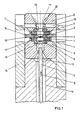
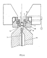
- FIG. 1, 1 denotes two disk-shaped or ring-shaped electrodes arranged parallel to one another, between which an insulator 2, for example made of ruby, sapphire or generally a non-conductive or poorly conductive oxide ceramic, is arranged, the insulator 2 being a passage opening 3, in which a plasma with small dimensions, which are ideally considered to be punctiform, is subsequently generated.
- an insulator 2 for example made of ruby, sapphire or generally a non-conductive or poorly conductive oxide ceramic
- Each electrode 1 has a passage opening 4 which considerably exceeds the dimensions of the passage opening 3 of the insulator, which define the dimensions of the plasma to be generated, indicated schematically by 17, and is approximately two to ten times the inside width of the opening 3 ,
- the electrodes 1 are mounted in schematically indicated brackets 5 and 6, respectively, via which a connection to a generator for supplying the energy for ignition and maintaining in the passage opening 3 of the insulator 2 is connected in a manner not shown, for example via a spring-loaded contact pin generating plasma takes place, a supply for a sample being designated 7.
- a plasma gas such as helium or argon
- an admixing gas such as CO 2 , Air, hydrogen or oxygen occurs in the area of the electrodes and insulators.
- Fig. 1 From Fig. 1 it can be seen that the in the feed direction 8 or 19 upstream of the sample and the plasma gas first electrode a further insulator 9 is provided, the passage opening 10 dimensions, which are essentially the dimensions of the passage opening 3 of the insulator 2, in which the plasma 17 is generated correspond to.
- This one in Flow direction 8 upstream insulator 9 is used in this essential to avoid penetration of the plasma into the Feed 7 and damage to the surrounding elements to avoid.
- the passage opening 12 is slightly smaller than the clear opening of the immediate neighboring electrode 1. Downstream through this Isolator 11 succeeds according to the requirements an optimization or precise definition of the plasma 17 radiation generated in the opening 3.
- the Passage opening 12 is at least slightly smaller than the passage opening 4 of the adjacent electrode 1 protected the electrode surface, and especially one spatial limitation of the glow discharge on the electrode achieved, whereby the energy consumption of the entire plasma as also the analytically interesting zone in the opening of the middle isolator is stabilized.
- the electrodes 1 can have sputtering effects at their edges be rounded or have no sharp burrs.
- the insulator 2 on its seen in the direction of flow 8 rear surface of a arcuate generatrix 13 is limited, so that in Insulator 2 has a reduced cross section in its central area results, so that seen in cross section in essential square dimensions of the passage opening 3 a spherical and idealized to be designated as a point Plasma 17 can be generated.
- the diameter of the passage opening 3 in the insulator 2, which defines the dimensions of the plasma to be generated, can be less than 0.5 mm and for example around 0.1 to 0.2 mm. In contrast, the diameter is 4 Openings of the electrodes 1, for example, about 0.5-1 mm.
- the thickness of the electrodes 1 and the insulators 2, 9 and 11 can be, for example, about 0.5 mm, with the Tapering of the insulator 2 in a central area correspondingly reduced thickness can be achieved.
- a plasma source can thus be achieved using structurally simple means to provide, in which the spatial Dimensions of the plasma are very small and precisely definable are, so that at atmospheric conditions a low energy Plasma with a power of less than 20, for example W and preferably between 5 and 10 W can be achieved.
- the low power also makes it possible safely dissipate the heat generated via the insulator 2, wherein, as can be seen from Fig. 1, the insulator 2 from one another insulator 14 is surrounded, which both the other Heat dissipation also serves as a safe shield of the two electrodes 1, which are located on both sides of the insulator 2 are arranged, allows.
- the Bracket 6 discharge or rinsing openings 15 indicated, about which is carried out according to the arrows 20.
- brackets 5 and 6 By providing the brackets 5 and 6 and the insulator 2 surrounding, additional insulator 14 succeeds safely Definition of the only small dimensions Individual elements, with a corresponding one gas-tight definition of the individual elements must become.
- the brackets 5, 6 are hiebei with centering devices trained or serve as the centering of the passage openings 3, 10, 12 of the individual elements, with a surrounding, electrically insulating Housing is indicated schematically at 16.
- brackets 5 and 6 at least in the area of the electrodes 1 and / or insulators 2, 9 and 11 adjacent or adjacent sealing surfaces coated, for example, are gold-plated.
- connection of the electrode 1 to the insulators 2, 9 and 11 can, for example, mechanically with the provision of appropriate Springs which compress the electrodes 1 and insulators 2, 9 and 11 bring with it, take place or it can be known metal-ceramic compounds, such as Soldering in a vacuum or in a hydrogen atmosphere, be used to create a correspondingly dense unit of Electrodes 1 and the insulators 2, 9 and 11 in the holders 5 and 6 or between them.
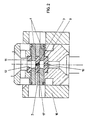
- Insulators 9 and 11 are the same Elements retain the reference numerals of the previous figure Service.
- a device which is used as a plasma reactor two are again essential for plasma generation annular electrodes 1 are provided, which insulators 2, 9 or 11 with very small passage cross-sections between or upstream or downstream.
- the storage of the Electrodes 1 and the insulators 2, 9 and 11 formed unit takes place again in brackets 5 and 6.
- the brackets 5 and 6 are from others electrical insulators 22 and 23 at least partially overlapped.
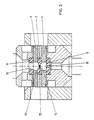
- an ion source can be a modified from the representation of FIG. 4 Connecting the supply source to the electrode, for example by swapping the connection for the earth potential, and be selected for the feeding of the RF energy.
- the area of plasma generation, as it passes through the electrodes 1 and the insulators 2, 9 and 11 is a schematically indicated shielding device 28 connected downstream, in front of this shielding device 28 for use in a mass spectrometer
- a fore vacuum is built up according to arrow 29, while subsequently in the area of the applied according to arrow 30 Reaction products a correspondingly higher vacuum is to be provided.
- a supply of an admixing gas may be provided. Furthermore, the upstream Bracket 24 again with appropriate, not heating devices shown in detail.
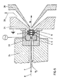
- the insulator 2 has a through opening 3 in which subsequently limits the plasma 17.
- the Feed for a sample is denoted by 7.
- the isolator 2 to limit the plasma 17 is again between two arranged in the form of rings or disks, the electrode 1 connected in the feed direction is again similar is formed to the preceding embodiments.
- the one in Feed direction seen upstream electrode together with an insulator connected upstream of the first electrode this unit is designated 31.
- the unit 31 is similar to the previous embodiments again an entry or passage opening 10, which essentially the passage opening 3 of the insulator 2 corresponds to the limitation of the plasma 17.
- the unit formed by the electrodes and the insulators is in turn accommodated in brackets, which in the Fig. 6 shown embodiment designated 33 and 34 are. From Fig. 6 it can also be seen that unequal the previous embodiments of the isolator 2 for limitation of the plasma 7 extends to the holders 33 and 34, so that overall in the embodiment shown in Fig. 6 with a reduced number of each other individual parts to be coordinated or connected the sufficiency can be found.
- both the electrodes and the insulator 2 to limit the plasma each with a large number formed by coordinated passage openings are, these through openings arranged here are that a concentration of the individual plasma sources output on a common Center or focus point can be achieved.
Landscapes
- Physics & Mathematics (AREA)
- Engineering & Computer Science (AREA)
- Plasma & Fusion (AREA)
- Spectroscopy & Molecular Physics (AREA)
- Electromagnetism (AREA)
- Geometry (AREA)
- Plasma Technology (AREA)
- Electron Sources, Ion Sources (AREA)
Description
Claims (25)
- Verfahren zum Erzeugen eines RF/HF-induzierten, niederenergetischen Plasmas (17), insbesondere Edelgasplasmas, dadurch gekennzeichnet, daß die Energie über zwei in Abstand parallel voneinander angeordnete, insbesondere ring- bzw. scheibenförmige, Elektroden (1, 31) mit jeweils wenigstens einer Durchtrittsöffnungen (4, 32) eingebracht wird, daß das Plasma (17) von wenigstens einem zwischen den Elektroden angeordneten Isolator (2) mit wenigstens einer der Durchtrittsöffnung (4, 32) der Elektrode (1, 31) zugeordneten, insbesondere kreisförmigen, Durchtrittsöffnung (3) begrenzt wird und daß der Druck des Plasmagases mit wenigstens 0,01 bar, vorzugsweise zwischen 0,1 und 5 bar, gewählt wird.
- Verfahren nach Anspruch 1, dadurch gekennzeichnet, daß das Plasma (17) bei atmosphärischem Druck erzeugt wird.
- Verfahren nach Anspruch 1 oder 2, dadurch gekennzeichnet, daß die Leistung des Plasmas (17) unter 30 W, vorzugsweise unter 10 W, gewählt wird.
- Verfahren nach einem der Ansprüche 1 bis 3, dadurch gekennzeichnet, daß die Frequenz mit wenigstens 5 kHz, vorzugsweise im Bereich zwischen 50 kHz und 5 GHz, insbesondere mindestens 10 MHz, gewählt wird.
- Verfahren nach einem der Ansprüche 1 bis 4, dadurch gekennzeichnet, daß das Plasmagas gewählt ist aus Helium oder Argon.
- Verfahren nach einem der Ansprüche 1 bis 5, dadurch gekennzeichnet, daß dem Plasmagas ein Zumischgas in einer Menge von maximal 35 Vol.-%, vorzugsweise max. 25 Vol.-%, zugemischt wird, wobei das Zumischgas insbesondere aus CO2, Luft, Wasserstoff und Sauerstoff gewählt wird.
- Vorrichtung zum Erzeugen eines RF/HF-induzierten, niederenergetischen Plasmas, insbesondere Edelgasplasmas, mit einem RF/HF- Generator und einer Zufuhr (7) für das Plasmagas, dadurch gekennzeichnet, daß der Generator mit zwei in Abstand parallel voneinander angeordneten, insbesondere ring- bzw. scheibenförmigen, Elektroden (1, 31) mit jeweils wenigstens einer Durchtrittsöffnung (4, 32) gekoppelt ist, daß zwischen den Elektroden (1, 31) wenigstens ein Isclator (2) mit wenigstens einer den Durchtrittsöffnungen der Elektroden (1) zugeordneten, insbesondere kreisförmigen, Durchtrittsöffnung (3) zur Begrenzung des von einem Plasmagas unter einem Druck von wenigstens 0,01 bar, vorzugsweise zwischen 0,1 und 5 bar, gebildeten Plasmas (17) angeordnet ist und daß die lichte Weite der Durchtrittsöffnung (4, 32) der Elektroden (1) wenigstens das Zweifache, insbesondere etwa das Vier- bis Achtfache, der lichten Weite der Durchtrittsöffnung (3) im Isolator (2) zur Begrenzung des Plasmas (17) beträgt.
- Vorrichtung nach Anspruch 7, dadurch gekennzeichnet, daß die Elektroden (1, 31) mit jeweils einer im wesentlichen zentrischen, insbesondere zylindrischen oder kagelstumpfförmigen, Durchtrittsöffnung (4, 32) ausgebildet sind.
- Vorrichtung nach Anspruch 7 oder 8, dadurch gekennzeichnet, daß die Durchtrittsöffnungen (4, 32) der Elektroden (1) mit abgerundeten Kanten ausgebildet sind.
- Vorrichtung nach einem der Ansprüche 7 bis 9, dadurch gekennzeichnet, daß die lichte Weite der Durchtrittsöffnung (3) im das Plasma (17) begrenzenden Isolator (2) maximal 1 mm, vorzugsweise mindestens 0,01 mm, insbesondere etwa 0,05 bis 0,3 mm, beträgt.
- Vorrichtung nach einem der Ansprüche 7 bis 10, dadurch gekennzeichnet, daß in Zufuhrrichtung (8) des Gases gesehen der ersten Elektrode (1) ein weiterer Isolator (9) mit einer der Durchtrittsöffnung (3) im zwischen den Elektroden (1) angeordneten Isolator (2) zur Begrenzung des Plasmas (17) im wesentlichen entsprechenden Durchtrittsöffnung (10) vorgeschaltet ist.
- Vorrichtung nach Anspruch 11, dadurch gekennzeichnet, daß die in Zufuhrrichtung des Gases gesehen erste Elektrode mit dem vorgeschalteten Isolator in einem gemeinsamen Bauteil (31) einstückig ausgebildet ist und daß an die der Durchtrittsöffnung (3) im Isolator (2) zur Begrenzung des Plasmas (17) entsprechende Durchtrittsöffnung (10) eine sich insbesondere konisch erweiternde Ausnehmung (32) anschließt.
- Vorrichtung nach einem der Ansprüche 7 bis 12, dadurch gekennzeichnet, daß in Zufuhrrichtung (8) des Gases gesehen der zweiten Elektrode (1) ein zusätzlicher Isolator (11) nachgeschaltet ist, dessen Durchtrittsöffnung (12) vorzugsweise geringfügig kleiner ist als die Durchtrittsöffnung (4) der benachbarten Elektrode (1).
- Vorrichtung nach einem der Ansprüche 7 bis 13, dadurch gekennzeichnet, daß der das Plasma begrenzende Isolator (2) scheibenförmig ausgebildet ist und in seinem die Durchtrittsöffnung (3) aufweisenden mittleren Bereich mit gegenüber den Randbereichen verringerter Dicke ausgebildet ist.
- Vorrichtung nach Anspruch 14, dadurch gekennzeichnet, daß die Verringerung der Dicke des Isolators (2) im mittleren Bereich im Querschnitt längs einer bogenförmigen, insbesondere kreisbogenförmigen, parabelförmigen oder kegelförmigen, Erzeugenden (13) verläuft.
- Vorrichtung nach einem der Ansprüche 7 bis 15, dadurch gekennzeichnet, daß das Material der Elektroden (1, 31) gewählt ist aus Gold, Platin, Tantal, Niob, Iridium, Aluminium, Platin/Iridium-Legierungen, vergoldetem Metall oder mit Edelmetallen galvanisch beschichteten, unedlen Metallen.
- Vorrichtung nach einem der Ansprüche 7 bis 16, dadurch gekennzeichnet, daß der das Plasma begrenzende Isolator (2) von Scheiben aus Aluminiumoxidkeramik, Quarz, Saphir, Rubin, Diamant oder elektrisch nicht- bzw. schlecht leitender Oxid-, Nitrid- oder Carbidkeramik gebildet ist.
- Vorrichtung nach einem der Ansprüche 7 bis 17, dadurch gekennzeichnet, daß die Elektroden (1, 31) und Isolatoren (2, 9, 11) entweder mechanisch, beispielsweise durch Federwirkung, miteinander zusammengepreßt sind oder durch an sich bekannte Metall-Keramik-Verbindungen, insbesondere durch Löten im Vakuum oder unter Wasserstoffatmosphäre, miteinander verbunden sind.
- Vorrichtung nach einem der Ansprüche 7 bis 18, dadurch gekennzeichnet, daß die Elektroden (1, 31) sowie der bzw. die Isolatoren (2, 9, 11) in Halterungen (5, 6, 21, 22, 23, 24, 33, 34) aufgenommen und gasdicht gelagert sind.
- Vorrichtung nach Anspruch 19, dadurch gekennzeichnet, daß die Halterungen (5, 6) mit Zentriereinrichtungen für die Elektroden (1) und/oder Isolatoren (2, 9, 11) ausgebildet sind.
- Vorrichtung nach Anspruch 19 oder 20, dadurch gekennzeichnet, daß die Halterungen (6) Abführ- und/oder Spülöffnungen (15), insbesondere für die Zufuhr eines Zumischgases, aufweisen.
- Vorrichtung nach Anspruch 19, 20 oder 21, dadurch gekennzeichnet, daß die Halterungen (5, 6) wenigstens im Bereich ihrer an den Elektroden (1) und/oder Isolatoren (2, 9, 11) anliegenden bzw. angrenzenden Dichtfläche beschichtet, beispielsweise vergoldet, sind.
- Vorrichtung nach einem der Ansprüche 19 bis 22, dadurch gekennzeichnet, daß die Halterungen (5, 6) für die Elektroden (1) mit Anschlüssen für die Zufuhr der RF/HF-Energie ausgebildet sind.
- Vorrichtung nach einem der Ansprüche 7 bis 23, dadurch gekennzeichnet, daß der das Plasma (17) begrenzende Isolator (2) von einem weiteren Isolator (14) umgeben ist, welcher den Isolator (2) zentriert und die Elektroden (1) voneinander abschirmt.
- Vorrichtung nach einem der Ansprüche 7 bis 24, dadurch gekennzeichnet, daß der Plasmaerzeugung eine Einrichtung zur Analyse von in das Plasma (17) eingebrachten, zu untersuchenden Materialien nachgeschaltet ist.
Applications Claiming Priority (3)
| Application Number | Priority Date | Filing Date | Title |
|---|---|---|---|
| AT36897 | 1997-03-04 | ||
| AT0036897A AT405472B (de) | 1997-03-04 | 1997-03-04 | Verfahren und vorrichtung zum erzeugen eines plasmas |
| PCT/AT1998/000048 WO1998039953A1 (de) | 1997-03-04 | 1998-03-03 | Verfahren und vorrichtung zum erzeugen eines plasmas |
Publications (2)
| Publication Number | Publication Date |
|---|---|
| EP0965253A1 EP0965253A1 (de) | 1999-12-22 |
| EP0965253B1 true EP0965253B1 (de) | 2003-06-11 |
Family
ID=3488746
Family Applications (1)
| Application Number | Title | Priority Date | Filing Date |
|---|---|---|---|
| EP98905135A Expired - Lifetime EP0965253B1 (de) | 1997-03-04 | 1998-03-03 | Verfahren und vorrichtung zum erzeugen eines plasmas |
Country Status (7)
| Country | Link |
|---|---|
| US (1) | US6169370B1 (de) |
| EP (1) | EP0965253B1 (de) |
| AT (1) | AT405472B (de) |
| AU (1) | AU743870B2 (de) |
| CA (1) | CA2283410C (de) |
| DE (1) | DE59808697D1 (de) |
| WO (1) | WO1998039953A1 (de) |
Families Citing this family (24)
| Publication number | Priority date | Publication date | Assignee | Title |
|---|---|---|---|---|
| DE19856307C1 (de) * | 1998-12-07 | 2000-01-13 | Bosch Gmbh Robert | Vorrichtung zur Erzeugung eines freien kalten Plasmastrahles |
| DE10259831B4 (de) * | 2002-12-19 | 2005-06-09 | Imt Innovative Messtechnik Gmbh | Plasmagenerator |
| US20040164250A1 (en) * | 2003-02-25 | 2004-08-26 | Cork Christopher P. | Handheld isotope identification system |
| SE529058C2 (sv) * | 2005-07-08 | 2007-04-17 | Plasma Surgical Invest Ltd | Plasmaalstrande anordning, plasmakirurgisk anordning, användning av en plasmakirurgisk anordning och förfarande för att bilda ett plasma |
| SE529056C2 (sv) * | 2005-07-08 | 2007-04-17 | Plasma Surgical Invest Ltd | Plasmaalstrande anordning, plasmakirurgisk anordning och användning av en plasmakirurgisk anordning |
| SE529053C2 (sv) | 2005-07-08 | 2007-04-17 | Plasma Surgical Invest Ltd | Plasmaalstrande anordning, plasmakirurgisk anordning och användning av en plasmakirurgisk anordning |
| US7812307B2 (en) * | 2006-01-20 | 2010-10-12 | Agilent Technologies, Inc. | Microplasma-based sample ionizing device and methods of use thereof |
| US7928338B2 (en) * | 2007-02-02 | 2011-04-19 | Plasma Surgical Investments Ltd. | Plasma spraying device and method |
| TWI337748B (en) * | 2007-05-08 | 2011-02-21 | Univ Nat Sun Yat Sen | Mass analyzing apparatus |
| US8735766B2 (en) * | 2007-08-06 | 2014-05-27 | Plasma Surgical Investments Limited | Cathode assembly and method for pulsed plasma generation |
| US7589473B2 (en) * | 2007-08-06 | 2009-09-15 | Plasma Surgical Investments, Ltd. | Pulsed plasma device and method for generating pulsed plasma |
| DE102009046504B4 (de) * | 2009-11-06 | 2016-06-09 | Westfälische Wilhelms-Universität Münster | Verfahren und Vorrichtung zum Analysieren eines Stoffgemisches |
| US20110109226A1 (en) * | 2009-11-06 | 2011-05-12 | Agilent Technologies, Inc. | Microplasma device with cavity for vacuum ultraviolet irradiation of gases and methods of making and using the same |
| US8613742B2 (en) * | 2010-01-29 | 2013-12-24 | Plasma Surgical Investments Limited | Methods of sealing vessels using plasma |
| US9089319B2 (en) | 2010-07-22 | 2015-07-28 | Plasma Surgical Investments Limited | Volumetrically oscillating plasma flows |
| CN102662018A (zh) * | 2010-11-30 | 2012-09-12 | 中国科学院大连化学物理研究所 | 一种光离子化检测器 |
| WO2012178177A2 (en) * | 2011-06-24 | 2012-12-27 | The Board Of Trustees Of The University Of Illinois | Microplasma jet devices, arrays, medical devices and methods |
| US9144858B2 (en) * | 2011-11-18 | 2015-09-29 | Recarbon Inc. | Plasma generating system having movable electrodes |
| RU2529056C2 (ru) * | 2012-12-14 | 2014-09-27 | Общество с ограниченной ответственностью "НИТ" | Высоковольтный плазмотрон |
| PL2804450T3 (pl) * | 2013-05-16 | 2022-12-19 | Kjellberg-Stiftung | Wieloelementowa część izolacyjna do palnika łukowo-plazmowego, palnik i układy z nim powiązane oraz powiązany sposób |
| JP6295150B2 (ja) * | 2014-07-07 | 2018-03-14 | 株式会社日立ハイテクノロジーズ | 質量分析装置 |
| JP6093915B1 (ja) * | 2015-03-27 | 2017-03-08 | 株式会社信光社 | 光アイソレータの放熱構造 |
| US10047437B2 (en) * | 2015-06-15 | 2018-08-14 | Inficon, Inc. | Process gas management system and photoionization detector |
| CA3191050A1 (en) | 2020-08-28 | 2022-03-03 | Nikolay Suslov | Systems, methods, and devices for generating predominantly radially expanded plasma flow |
Family Cites Families (13)
| Publication number | Priority date | Publication date | Assignee | Title |
|---|---|---|---|---|
| US2941063A (en) * | 1958-09-15 | 1960-06-14 | Plasmadyne Corp | Plasma-jet torch apparatus and method relating to increasing the life of the back electrode |
| DE1263201B (de) * | 1959-11-14 | 1968-03-14 | Kralovopolska Strojirna Zd Y C | Vorrichtung zur Erzeugung und Aufrechterhaltung eines im Inneren eines laenglichen Fluessigkeitswirbels brennenden elektrischen Lichtbogens |
| US3149222A (en) * | 1962-08-21 | 1964-09-15 | Giannini Scient Corp | Electrical plasma-jet apparatus and method incorporating multiple electrodes |
| DE1614801C3 (de) * | 1966-04-16 | 1973-09-27 | Tavkoezlesi Kutato Intezet, Budapest | Senkrecht angeordneter Licht bogen Plasmabrenner |
| FR1581300A (de) * | 1967-09-09 | 1969-09-12 | ||
| DE2525939A1 (de) * | 1975-06-11 | 1976-12-23 | Messer Griesheim Gmbh | Plasmalichtbogenbrenner |
| DE2646785A1 (de) * | 1976-10-16 | 1978-04-20 | Battelle Institut E V | Plasma-panel |
| US4854263B1 (en) * | 1987-08-14 | 1997-06-17 | Applied Materials Inc | Inlet manifold and methods for increasing gas dissociation and for PECVD of dielectric films |
| GB2255856B (en) * | 1988-01-07 | 1993-01-27 | Toshiba Kk | Apparatus for introducing samples into an inductively coupled,plasma source mass spectrometer |
| DE3814330C2 (de) * | 1988-04-28 | 1997-05-15 | Rheinmetall Ind Ag | Elektrothermische Beschleunigungsvorrichtung |
| US5414324A (en) * | 1993-05-28 | 1995-05-09 | The University Of Tennessee Research Corporation | One atmosphere, uniform glow discharge plasma |
| JPH08274069A (ja) * | 1995-03-30 | 1996-10-18 | Sumitomo Sitix Corp | プラズマエッチング装置用シリコン電極装置 |
| JP3082659B2 (ja) * | 1996-03-18 | 2000-08-28 | 株式会社日立製作所 | プラズマ処理装置 |
-
1997
- 1997-03-04 AT AT0036897A patent/AT405472B/de not_active IP Right Cessation
-
1998
- 1998-03-03 EP EP98905135A patent/EP0965253B1/de not_active Expired - Lifetime
- 1998-03-03 WO PCT/AT1998/000048 patent/WO1998039953A1/de not_active Ceased
- 1998-03-03 CA CA002283410A patent/CA2283410C/en not_active Expired - Fee Related
- 1998-03-03 AU AU60809/98A patent/AU743870B2/en not_active Ceased
- 1998-03-03 DE DE59808697T patent/DE59808697D1/de not_active Expired - Fee Related
-
1999
- 1999-09-03 US US09/389,349 patent/US6169370B1/en not_active Expired - Fee Related
Also Published As
| Publication number | Publication date |
|---|---|
| AU6080998A (en) | 1998-09-22 |
| AU743870B2 (en) | 2002-02-07 |
| EP0965253A1 (de) | 1999-12-22 |
| WO1998039953A1 (de) | 1998-09-11 |
| ATA36897A (de) | 1998-12-15 |
| CA2283410C (en) | 2002-11-12 |
| US6169370B1 (en) | 2001-01-02 |
| DE59808697D1 (de) | 2003-07-17 |
| AT405472B (de) | 1999-08-25 |
| CA2283410A1 (en) | 1998-09-11 |
Similar Documents
| Publication | Publication Date | Title |
|---|---|---|
| AT405472B (de) | Verfahren und vorrichtung zum erzeugen eines plasmas | |
| EP0315986B1 (de) | Filamentlose Magnetron-Ionenquelle und Verwendungsverfahren | |
| EP0349556B1 (de) | Verfahren und vorrichtung zur bearbeitung von festkörperoberflächen durch teilchenbeschuss | |
| DE69809943T2 (de) | Glimmentladungs-plasmavorrichung | |
| DE3905303C2 (de) | Vorrichtung zur Erzeugung eines Plasmas durch Mikrowellen | |
| DE10151080C1 (de) | Einrichtung und Verfahren zum Erzeugen von extrem ultravioletter (EUV-)Strahlung auf Basis einer Gasentladung | |
| DE112011104535B4 (de) | Gerät für einen Strahl von geladenen Teilchen | |
| EP1557667B1 (de) | Gasanalyseverfahren und ionisationsdetektor zur ausführung des verfahrens | |
| DE69522826T2 (de) | Radiofrequenz-ionenquelle | |
| EP2082221B1 (de) | Verfahren zur erzeugung von positiv und/oder negativ ionisierten gasanalyten für die gasanalyse | |
| EP0247397A2 (de) | Vorrichtung zur Oberflächenbehandlung von Werkstücken | |
| DE2602078C3 (de) | Niederdruck-Gasentladungsröhre | |
| DE102004029466A1 (de) | Medieninjektor | |
| EP3808160B1 (de) | Vorrichtung zum erzeugen einer filamentierten hilfsentladung für eine vorrichtung zum erzeugen von röntgenstrahlung und partikelstrahlung sowie für einen fusionsreaktor mit der vorrichtung zum erzeugen von röntgenstrahlung und partikelstrahlung und verfahren zum erzeugen von röntgenstrahlung und partikelstrahlung | |
| AT406527B (de) | Vorrichtung zum analysieren gasförmiger proben | |
| EP1369001A1 (de) | Verfahren zum plasmaschweissen | |
| Penache | Study of high-pressure glow discharges generated by micro-structured electrode (MSE) arrays | |
| DE3014151A1 (de) | Generator fuer gepulste elektronenstrahlen | |
| DE1929429A1 (de) | Verfahren und Vorrichtung zur Anregung eines spektrochemisch zu untersuchenden Materials | |
| DE69804772T2 (de) | Element-selektives detektionsverfahren, mikro-plasma massenspektrometer und mikro-plasma ionenquelle dafür sowie ihre anwendungen | |
| DE19628093B4 (de) | Verfahren und Vorrichtung zum Nachweis von Probenmolekülen | |
| EP0021204A1 (de) | Ionengenerator | |
| DE19718660A1 (de) | Verfahren zur Triggerung einer gasisolierten Schaltfunkenstrecke und Vorrichtung zur Anwendung des Verfahrens | |
| DE10010706A1 (de) | Hohlkathoden-Sputter-Ionenquelle zur Erzeugung von Ionenstrahlen hoher Intensität | |
| DE2523360B2 (de) | Gasentladungselektronenstrahlerzeugungssystem zum erzeugen eines elektronenstrahls mit hilfe einer glimmentladung |
Legal Events
| Date | Code | Title | Description |
|---|---|---|---|
| PUAI | Public reference made under article 153(3) epc to a published international application that has entered the european phase |
Free format text: ORIGINAL CODE: 0009012 |
|
| 17P | Request for examination filed |
Effective date: 19991004 |
|
| AK | Designated contracting states |
Kind code of ref document: A1 Designated state(s): DE FR GB IT |
|
| GRAG | Despatch of communication of intention to grant |
Free format text: ORIGINAL CODE: EPIDOS AGRA |
|
| 17Q | First examination report despatched |
Effective date: 20020502 |
|
| GRAG | Despatch of communication of intention to grant |
Free format text: ORIGINAL CODE: EPIDOS AGRA |
|
| GRAH | Despatch of communication of intention to grant a patent |
Free format text: ORIGINAL CODE: EPIDOS IGRA |
|
| GRAH | Despatch of communication of intention to grant a patent |
Free format text: ORIGINAL CODE: EPIDOS IGRA |
|
| GRAA | (expected) grant |
Free format text: ORIGINAL CODE: 0009210 |
|
| AK | Designated contracting states |
Designated state(s): DE FR GB IT |
|
| PG25 | Lapsed in a contracting state [announced via postgrant information from national office to epo] |
Ref country code: IT Free format text: LAPSE BECAUSE OF FAILURE TO SUBMIT A TRANSLATION OF THE DESCRIPTION OR TO PAY THE FEE WITHIN THE PRESCRIBED TIME-LIMIT;WARNING: LAPSES OF ITALIAN PATENTS WITH EFFECTIVE DATE BEFORE 2007 MAY HAVE OCCURRED AT ANY TIME BEFORE 2007. THE CORRECT EFFECTIVE DATE MAY BE DIFFERENT FROM THE ONE RECORDED. Effective date: 20030611 Ref country code: GB Free format text: LAPSE BECAUSE OF FAILURE TO SUBMIT A TRANSLATION OF THE DESCRIPTION OR TO PAY THE FEE WITHIN THE PRESCRIBED TIME-LIMIT Effective date: 20030611 Ref country code: FR Free format text: LAPSE BECAUSE OF FAILURE TO SUBMIT A TRANSLATION OF THE DESCRIPTION OR TO PAY THE FEE WITHIN THE PRESCRIBED TIME-LIMIT Effective date: 20030611 |
|
| REG | Reference to a national code |
Ref country code: GB Ref legal event code: FG4D Free format text: NOT ENGLISH |
|
| REF | Corresponds to: |
Ref document number: 59808697 Country of ref document: DE Date of ref document: 20030717 Kind code of ref document: P |
|
| GBV | Gb: ep patent (uk) treated as always having been void in accordance with gb section 77(7)/1977 [no translation filed] |
Effective date: 20030611 |
|
| PLBE | No opposition filed within time limit |
Free format text: ORIGINAL CODE: 0009261 |
|
| STAA | Information on the status of an ep patent application or granted ep patent |
Free format text: STATUS: NO OPPOSITION FILED WITHIN TIME LIMIT |
|
| 26N | No opposition filed |
Effective date: 20040312 |
|
| EN | Fr: translation not filed | ||
| PGFP | Annual fee paid to national office [announced via postgrant information from national office to epo] |
Ref country code: DE Payment date: 20070925 Year of fee payment: 10 |
|
| PG25 | Lapsed in a contracting state [announced via postgrant information from national office to epo] |
Ref country code: DE Free format text: LAPSE BECAUSE OF NON-PAYMENT OF DUE FEES Effective date: 20081001 |