EP0965397A1 - Rolle mit knotigen Ringen - Google Patents
Rolle mit knotigen Ringen Download PDFInfo
- Publication number
- EP0965397A1 EP0965397A1 EP99304393A EP99304393A EP0965397A1 EP 0965397 A1 EP0965397 A1 EP 0965397A1 EP 99304393 A EP99304393 A EP 99304393A EP 99304393 A EP99304393 A EP 99304393A EP 0965397 A1 EP0965397 A1 EP 0965397A1
- Authority
- EP
- European Patent Office
- Prior art keywords
- roller
- nodes
- node
- backing
- sheet material
- Prior art date
- Legal status (The legal status is an assumption and is not a legal conclusion. Google has not performed a legal analysis and makes no representation as to the accuracy of the status listed.)
- Withdrawn
Links
- 239000000463 material Substances 0.000 claims abstract description 96
- 238000000034 method Methods 0.000 claims abstract description 23
- 229910052751 metal Inorganic materials 0.000 claims description 13
- 239000002184 metal Substances 0.000 claims description 13
- 230000000295 complement effect Effects 0.000 claims description 11
- 239000007769 metal material Substances 0.000 claims description 10
- 238000005452 bending Methods 0.000 claims description 9
- 230000002093 peripheral effect Effects 0.000 description 5
- 230000007423 decrease Effects 0.000 description 2
- 230000000694 effects Effects 0.000 description 2
- 230000000704 physical effect Effects 0.000 description 2
- 229920004943 Delrin® Polymers 0.000 description 1
- 229910000831 Steel Inorganic materials 0.000 description 1
- MUBKMWFYVHYZAI-UHFFFAOYSA-N [Al].[Cu].[Zn] Chemical compound [Al].[Cu].[Zn] MUBKMWFYVHYZAI-UHFFFAOYSA-N 0.000 description 1
- 125000000218 acetic acid group Chemical group C(C)(=O)* 0.000 description 1
- 230000015572 biosynthetic process Effects 0.000 description 1
- 238000000926 separation method Methods 0.000 description 1
- 239000010959 steel Substances 0.000 description 1
Images


Classifications
-
- B—PERFORMING OPERATIONS; TRANSPORTING
- B21—MECHANICAL METAL-WORKING WITHOUT ESSENTIALLY REMOVING MATERIAL; PUNCHING METAL
- B21D—WORKING OR PROCESSING OF SHEET METAL OR METAL TUBES, RODS OR PROFILES WITHOUT ESSENTIALLY REMOVING MATERIAL; PUNCHING METAL
- B21D5/00—Bending sheet metal along straight lines, e.g. to form simple curves
- B21D5/06—Bending sheet metal along straight lines, e.g. to form simple curves by drawing procedure making use of dies or forming-rollers, e.g. making profiles
- B21D5/08—Bending sheet metal along straight lines, e.g. to form simple curves by drawing procedure making use of dies or forming-rollers, e.g. making profiles making use of forming-rollers
-
- B—PERFORMING OPERATIONS; TRANSPORTING
- B21—MECHANICAL METAL-WORKING WITHOUT ESSENTIALLY REMOVING MATERIAL; PUNCHING METAL
- B21D—WORKING OR PROCESSING OF SHEET METAL OR METAL TUBES, RODS OR PROFILES WITHOUT ESSENTIALLY REMOVING MATERIAL; PUNCHING METAL
- B21D13/00—Corrugating sheet metal, rods or profiles; Bending sheet metal, rods or profiles into wave form
- B21D13/04—Corrugating sheet metal, rods or profiles; Bending sheet metal, rods or profiles into wave form by rolling
- B21D13/045—Corrugating sheet metal, rods or profiles; Bending sheet metal, rods or profiles into wave form by rolling the corrugations being parallel to the feeding movement
Definitions
- This invention relates to forming curves in sheet material and more particularly to a method and apparatus for roll forming curved shapes resembling large radius curves in a sheet material, particularly sheet metal, with a minimum return or spring back to the original shape.
- Sheet metal materials for which roll forming is carried out to form radius curves typically ranges from 0.01 inch to 0.10 inch (0.254 to 2.54 mm) in thickness.
- Metallic or sheet metal materials have both elastic and ductile properties. When sheet metal is bent or formed below its elastic limit, it will spring back to its original shape. The elastic limit must be exceeded to effect permanent deformation, i.e. a bend. In bending sheet metal to a selected angle/radius, a certain amount of spring-back or return to the original shape will take place. Although a portion of the metal in a bend is permanently deformed, portions of any bend will remain below the elastic limit and cause spring-back. In order to achieve a finished bend angle/radius, the sheet metal must be over bent. A technique for overbending is disclosed in U.S. Patent No. 5,551,272. This might include bending through a larger angle, bending with a smaller inside bend radius, or both.
- a small radius bend is a bend whose inside bend radius measures between zero to five times the material thickness.
- a large radius bend is above five times the material thickness.
- a typical sheet metal material having a 0.03 inch (0.762 mm) thickness then a large radius bend is 0.15 inch (3.81 mm) and above.
- a method and apparatus for forming curved shapes in a sheet material in such a way as to minimize the tendency of the material to return to an original shape.
- a sheet metal is passed between a series of spaced nodes on a node roller. The series may follow a flat or curved surface.
- a backing roller with a smooth outer surface is opposite the node roller and has an outer surface complementary with the outer surface of the node roller with the sheet being passed therebetween.
- the node rollers form a plurality of small radius small angle bends between substantially flat segments to provide a curved shape resembling a true large radius curve. Curved shapes in gutter hoods and half round gutters are disclosed.
- a second method discloses the forming of a curve in the bottom wall of a gutter using smooth roller surfaces before forming the series of bends and flat segments so as to reduce the tendency of the material to return to the original state.
- FIG. 1-3 there is shown roll forming apparatus having two stations or stages for forming a curved shape resembling a radius curve in a sheet material.
- the element shown being formed is a hood for a gutter described in U.S. Patent No. 5,845,435.
- an upper node roller 21 is typically mounted on an upper shaft rotatable in suitable bearings in side supports for rotation about an axis of rotation 22.
- Roller 21 has an outer peripheral curved surface 23 extending generally along a convex curve of a selected radius designated R1 and is shown as formed with a series of eight laterally spaced ring-shaped, circumferential protuberances or nodes 24 having a selected radius designated R and a selected spacing designated S between nodes ( Figure 1A).
- the node roller 21 preferably is made of a material at least as hard as the sheet metal 25 being shaped.
- a lower backing roller 26 is typically mounted on a lower shaft rotatable in suitable bearings in side supports for rotation about an axis of rotation 27.
- Backing roller 26 has a smooth outer concave surface 28 having a curvature that is complementary with or matches with the convex curve of surface 23 of roller 21.
- the backing roller 26 is made of a material substantially softer or weaker than the sheet material being formed. 5
- the clearance between the opposing rollers, preferably, is a distance that measures less than the thickness of the sheet material to be formed.
- a typical material for the backing roller is acetyl plastic (Delrin).
- a typical node radius R is 0.25 inches (6.35 mm) and node spacing S is 0.50 inches (12.7 mm) for the first stage for making a gutter hood.
- the outer curved surface R1 has a radius of 15 inches (381 mm).
- an upper node roller 31 that rotates about an axis of rotation 32.
- the node roller 31 has an outer peripheral surface 33 arranged along a convex curve of a selected radius smaller than radius R1.
- This upper node roller 31 shown has a series of eight laterally spaced ring shaped circumferential nodes 34 formed in the outer surface 33.
- a lower backing roller 36 opposite node roller 31 rotates about an axis of rotation 37.
- Backing roller 36 has a smooth generally concave outer surface 38 that matches or is complementary with surface 33.
- the hood cover 25A with a curved wall is shown as formed between the rollers 31 and 36.
- the nodes 34 on the second stage node roller 31 are located between the nodes 24 on the first stage node roller to form bends and angles in the material between the bends formed in the first stage to further increase the curvature in the material being shaped.
- the angle between the flat faces decreases by one half and the width of the flat segments decreases by one half.
- the node radius R is 0.25 inches (6.35 mm)
- the spacing C is 0.25 inches (6.35 mm)
- the radius of curves 33 and 38 is 8 inches (210 mm).
- the roller stages achieve a 10 inch (254 mm) bend through an arc of about 25 degrees. There are 15 bends of approximately 1 1 ⁇ 2 degrees each.
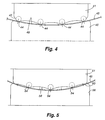
- FIG. 4-6 there is shown schematically rollers in roll forming apparatus from three stages for forming a curved shape such as the bottom wall of a half round gutter.
- the first stage has an upper node roller 41 rotating about an axis.
- Node roller 41 has an outer peripheral surface 43 arranged along a concave curve of a selected radius.
- Node roller 41 has a series of four ring shaped circumferential spaced nodes 44 spaced across the surface of a sheet material 45.
- a backing roller 46 opposite node roller 41 rotates about an axis.
- Backing roller 46 has a concavely curved outer surface 48 that matches or is complementary with the convex curve 43 of the outer surface of node roller 41.
- the second stage ( Figure 5) has an upper node roller 51 rotating about an axis.
- Roller 51 has an outer peripheral surface 53 arranged along a concave curve of a selected radius smaller than the nodes of the first stage.
- Node roller 51 has three laterally spaced ring shaped circumferential nodes 54. These nodes 54 are located between the nodes 44 of the first stage to further bend the sheet material 45.
- a backing roller 56 opposite node roller 51 rotates about an axis.
- Backing roller 56 has a concavely curved outer surface 58 that matches or is complementary to the curve 53 of the outer surface of node roller 51.
- the third stage ( Figure 6) has an upper node roller 61 rotating about an axis.
- Roller 61 has an outer peripheral surface 63 arranged along a concave curve of a selected radius smaller than the radius of the previous stage.
- Roller 61 has six laterally spaced ring shaped circumferential nodes 64 located between the nodes 54 of the second stage to further bend the sheet metal 45.
- a backing roller 66 opposite roller 61 rotates about an axis.
- Roller 66 has a concavely curved surface 68 that matches the curve of surface 63.
- the half round gutter will have approximately 60 bends of three degrees each to achieve a finished bend of 180 degrees.
- the term "small angle" as referred to herein is preferably below 25 degrees and typically 5 degrees or less.
- the roll forming apparatus has a smooth convex upper roller 71 with a smooth convexly curved surface 73 of a selected radius. As shown the radius is semi-circular to form a semi-circular shape in the bottom wall of a gutter.
- a lower roller 76 opposite roller 71 has a complementary smooth concave surface 78.
- a sheet material 75 is passed between the rollers. In this procedure a curve is formed prior to using the node and backing rollers.
- the second stage ( Figure 8) has an upper node roller 84 rotating about an axis.
- the node roller 84 has an outer surface 86 arranged along a concave surface of a selected radius.
- the node roller has a series of five laterally spaced ring shaped circumferential nodes 87.
- Opposite the node roller 84 is a backing roller 88 that rotates about an axis.
- the material 73 passes between the node and backing rollers.
- the backing roller 88 has a concavely outer curved surface 90 that matches the curve of surface 86 of the node roller 84.
- the third stage ( Figure 9) has an upper node roller 91 rotating about an axis.
- the upper node roller has an outer surface 93 arranged along a convex curve of a selected radius.
- Node roller 91 has a series of four spaced ring shaped circumferential nodes 94 located between the nodes of the second stage to further bend the sheet material 75.
- a backing roller 96 is opposite the node roller and rotates about an axis.
- the backing roller has a concavely curved outer surface 98 that matches the curve of the outer surface 93 of the node roller 91.
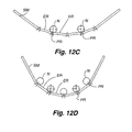
- the present invention may be further explained with reference to a sequence illustrated in Figure 11 and Figures 12A to 12D.
- the initial sheet material is a relaxed flat sheet not shown.
- the relaxed flat sheet material is engaged by a plurality or series of ring shaped circumferential nodes N (three shown) which are spaced across the top surface of the sheet material SM. This series may follow a flat or curved surface.
- Elastic as used herein means the material returns to an original shape and plastic deformation means the material is permanently deformed.
- the cross section of the material becomes a series of small bends SB and small angles between flat segments with regions of plastic deformation PR at the bends.
- the nodes are organized in sequential passes to form bends in different parts of the sheet at different times. In this way, the nodes may remain appropriately spaced, while minimizing the overall separation between the small, closely spaced bends. It is important to note that previously deformed plastic regions will exhibit essentially elastic behavior when they pass through rollers in an elastic region. Just as in the case of the flat segment that flexes and springs back, a region that has experience plastic deformation will elastically deform, and then return to its previously bend state.
- the first pass through the nodes N causes plastic regions PR at the node and elastic regions ER between regions PR that will return to a relaxed state when the sheet is relaxed.
- Figure 12B shows a relaxed sheet after the pass through the nodes where the elastic regions return to a relaxed state and there is permanent deformation in the plastic regions PR.
- Figure 12C shows a second pass through two spaced nodes N between or offset from the nodes of the preceding stage. The previously formed plastic regions PR become part of new elastic regions ER.
- Figure 12D shows a relaxed sheet after passing through the nodes showing small closely spaced deformations (bends) that provide the appearance or resemblance of a true large radius bend.
- An advantage of the above described method and apparatus is the ability to bend different thicknesses of material and different materials accurately. Further, curves can be made in any arc or segment of a circle as required.
Landscapes
- Engineering & Computer Science (AREA)
- Mechanical Engineering (AREA)
- Bending Of Plates, Rods, And Pipes (AREA)
Applications Claiming Priority (2)
| Application Number | Priority Date | Filing Date | Title |
|---|---|---|---|
| US8824798P | 1998-06-05 | 1998-06-05 | |
| US88247P | 1998-06-05 |
Publications (1)
| Publication Number | Publication Date |
|---|---|
| EP0965397A1 true EP0965397A1 (de) | 1999-12-22 |
Family
ID=22210251
Family Applications (1)
| Application Number | Title | Priority Date | Filing Date |
|---|---|---|---|
| EP99304393A Withdrawn EP0965397A1 (de) | 1998-06-05 | 1999-06-04 | Rolle mit knotigen Ringen |
Country Status (2)
| Country | Link |
|---|---|
| US (1) | US6119498A (de) |
| EP (1) | EP0965397A1 (de) |
Cited By (1)
| Publication number | Priority date | Publication date | Assignee | Title |
|---|---|---|---|---|
| GB2565410A (en) * | 2017-06-16 | 2019-02-13 | Gram Engineering Pty Ltd | Corrugated sheet and method of manufacturing same |
Families Citing this family (7)
| Publication number | Priority date | Publication date | Assignee | Title |
|---|---|---|---|---|
| KR20040092990A (ko) * | 2003-04-30 | 2004-11-04 | 정운진 | 롤 포밍용 롤 및 롤 포밍 방법 |
| US20060021286A1 (en) * | 2004-07-30 | 2006-02-02 | Saville James L Jr | Dual flow gutter assembly |
| NZ564570A (en) * | 2007-12-18 | 2010-02-26 | Scott Technology Ltd | Metal folding apparatus |
| US20100012669A1 (en) * | 2008-07-15 | 2010-01-21 | Delta Consolidated Industries | Panels for a Container Joint Including a Three Dimensional Pattern on a Portion Thereof and Methods of Forming Same |
| US9283604B2 (en) * | 2008-12-05 | 2016-03-15 | Ted Baum, Jr. | Metal simulated log siding panel with hew lines and method of making and using same |
| USD602612S1 (en) | 2008-12-05 | 2009-10-20 | Baum Jr Ted | Metal simulated log siding panel |
| JP2016048277A (ja) * | 2014-08-27 | 2016-04-07 | 株式会社リコー | 電気粘着力発現部材を有するベルト駆動ローラ及びそれを用いたベルト駆動装置 |
Citations (5)
| Publication number | Priority date | Publication date | Assignee | Title |
|---|---|---|---|---|
| FR881093A (fr) * | 1942-04-08 | 1943-04-14 | Ziegler Ets | Procédé et machine pour onduler les tôles en long |
| FR1464663A (fr) * | 1965-09-14 | 1967-01-06 | Dispositifs pour galber, onduler et cintrer les tôles | |
| US4553418A (en) * | 1984-03-15 | 1985-11-19 | Artos Engineering Company | Apparatus for producing elongated workpieces of predetermined transverse profile |
| EP0164233A2 (de) * | 1984-06-01 | 1985-12-11 | ALLIED TUBE & CONDUIT CORPORATION | Vorrichtung zur Herstellung eines gerippten Rohres |
| EP0515190A1 (de) * | 1991-05-24 | 1992-11-25 | Gutterfast Limited | Herstellung von U-Profilen aus einem flachen Metallstreifen |
Family Cites Families (6)
| Publication number | Priority date | Publication date | Assignee | Title |
|---|---|---|---|---|
| DE629644C (de) * | 1936-05-11 | Henschel Flugzeug Werke Akt Ge | Einrichtung zum Ziehen von Profilen aus Metallband | |
| US3059685A (en) * | 1957-09-09 | 1962-10-23 | Walter D Behlen | Corrugated panel making machine and method |
| US3187539A (en) * | 1960-05-17 | 1965-06-08 | Continental Can Co | Roll forming of sheet material |
| US3150707A (en) * | 1961-04-27 | 1964-09-29 | Howell Pat | Apparatus for making metal building and building elements |
| AT238670B (de) * | 1961-07-28 | 1965-02-25 | Voest Ag | Verfahren und Einrichtung zur Herstellung und allfälligen Verbindung von Profilen |
| US3344641A (en) * | 1965-08-11 | 1967-10-03 | Eastern Prod Corp | Method for treating sheet metal strip |
-
1999
- 1999-05-28 US US09/322,783 patent/US6119498A/en not_active Expired - Fee Related
- 1999-06-04 EP EP99304393A patent/EP0965397A1/de not_active Withdrawn
Patent Citations (5)
| Publication number | Priority date | Publication date | Assignee | Title |
|---|---|---|---|---|
| FR881093A (fr) * | 1942-04-08 | 1943-04-14 | Ziegler Ets | Procédé et machine pour onduler les tôles en long |
| FR1464663A (fr) * | 1965-09-14 | 1967-01-06 | Dispositifs pour galber, onduler et cintrer les tôles | |
| US4553418A (en) * | 1984-03-15 | 1985-11-19 | Artos Engineering Company | Apparatus for producing elongated workpieces of predetermined transverse profile |
| EP0164233A2 (de) * | 1984-06-01 | 1985-12-11 | ALLIED TUBE & CONDUIT CORPORATION | Vorrichtung zur Herstellung eines gerippten Rohres |
| EP0515190A1 (de) * | 1991-05-24 | 1992-11-25 | Gutterfast Limited | Herstellung von U-Profilen aus einem flachen Metallstreifen |
Cited By (2)
| Publication number | Priority date | Publication date | Assignee | Title |
|---|---|---|---|---|
| GB2565410A (en) * | 2017-06-16 | 2019-02-13 | Gram Engineering Pty Ltd | Corrugated sheet and method of manufacturing same |
| GB2565410B (en) * | 2017-06-16 | 2020-08-26 | Gram Engineering Pty Ltd | Corrugated sheet and method of manufacturing same |
Also Published As
| Publication number | Publication date |
|---|---|
| US6119498A (en) | 2000-09-19 |
Similar Documents
| Publication | Publication Date | Title |
|---|---|---|
| US6119498A (en) | Node roller combination | |
| JP2531656B2 (ja) | 往復動ピストン・エンジン用カム軸の製法 | |
| EP1600648B1 (de) | Geschlitztes Wälzlager mit einem geschlitzten Wälzlagerring | |
| ES2016061A6 (es) | Plancha en sandwich perfeccionada y procedimiento para flexion de la misma. | |
| US5158814A (en) | Flexible metal conduit and method of making the same | |
| EP0334123A2 (de) | Walze mit gekrümmter Achse | |
| US4617717A (en) | Composite member comprising metallic sheet bent to be arcuate in section and rigid synthetic resin coating | |
| GB2136064A (en) | Friction clutch | |
| BR0204229A (pt) | Método de formar um copo de metal laminado sem um mandril | |
| US500119A (en) | Ferdinand dieckmann | |
| JP2747996B2 (ja) | 曲率調整ロールを用いた2本ロール成形機 | |
| US6115920A (en) | Method of manufacturing multi-grooved V pulley | |
| SU1639830A1 (ru) | Инструмент профилегибочного стана | |
| SU778862A1 (ru) | Способ производства профилей с гофрами | |
| JP4906986B2 (ja) | ロール成形方法 | |
| SU1268094A3 (ru) | Способ изготовлени ребристых труб из биметаллических трубных заготовок и набор инструмента дл изготовлени ребристых труб | |
| RU2036036C1 (ru) | Способ правки с растяжением движущейся стальной полосы | |
| JP3157989B2 (ja) | アングル材製造方法 | |
| RU1771846C (ru) | Способ изготовлени профилей | |
| RU2008115C1 (ru) | Способ поштучного профилирования полукруглых гофр на листе | |
| WO1993013892A1 (en) | Wire straightening method | |
| JPS6114072B2 (de) | ||
| JPH01247364A (ja) | 曲軸胴太ロール及びピンチ装置 | |
| SU1544519A1 (ru) | Комплект валков листогибочной машины | |
| SU1329863A1 (ru) | Способ формировани рулона из длинномерного металлического материала |
Legal Events
| Date | Code | Title | Description |
|---|---|---|---|
| PUAI | Public reference made under article 153(3) epc to a published international application that has entered the european phase |
Free format text: ORIGINAL CODE: 0009012 |
|
| AK | Designated contracting states |
Kind code of ref document: A1 Designated state(s): AT BE CH DE ES FI FR GB LI PT SE |
|
| AX | Request for extension of the european patent |
Free format text: AL;LT;LV;MK;RO;SI |
|
| 17P | Request for examination filed |
Effective date: 20000515 |
|
| AKX | Designation fees paid |
Free format text: AT BE CH CY DE DK ES FI FR GB LI |
|
| RBV | Designated contracting states (corrected) |
Designated state(s): AT BE CH DE ES FI FR GB LI PT SE |
|
| 17Q | First examination report despatched |
Effective date: 20020917 |
|
| GRAP | Despatch of communication of intention to grant a patent |
Free format text: ORIGINAL CODE: EPIDOSNIGR1 |
|
| STAA | Information on the status of an ep patent application or granted ep patent |
Free format text: STATUS: THE APPLICATION IS DEEMED TO BE WITHDRAWN |
|
| 18D | Application deemed to be withdrawn |
Effective date: 20040203 |