EP0965406A2 - Outil de forage - Google Patents
Outil de forage Download PDFInfo
- Publication number
- EP0965406A2 EP0965406A2 EP99810526A EP99810526A EP0965406A2 EP 0965406 A2 EP0965406 A2 EP 0965406A2 EP 99810526 A EP99810526 A EP 99810526A EP 99810526 A EP99810526 A EP 99810526A EP 0965406 A2 EP0965406 A2 EP 0965406A2
- Authority
- EP
- European Patent Office
- Prior art keywords
- centering
- cutting
- cutting edges
- drilling tool
- drilling
- Prior art date
- Legal status (The legal status is an assumption and is not a legal conclusion. Google has not performed a legal analysis and makes no representation as to the accuracy of the status listed.)
- Granted
Links
Images
Classifications
-
- B—PERFORMING OPERATIONS; TRANSPORTING
- B23—MACHINE TOOLS; METAL-WORKING NOT OTHERWISE PROVIDED FOR
- B23B—TURNING; BORING
- B23B51/00—Tools for drilling machines
-
- B—PERFORMING OPERATIONS; TRANSPORTING
- B23—MACHINE TOOLS; METAL-WORKING NOT OTHERWISE PROVIDED FOR
- B23B—TURNING; BORING
- B23B2251/00—Details of tools for drilling machines
- B23B2251/14—Configuration of the cutting part, i.e. the main cutting edges
-
- B—PERFORMING OPERATIONS; TRANSPORTING
- B23—MACHINE TOOLS; METAL-WORKING NOT OTHERWISE PROVIDED FOR
- B23B—TURNING; BORING
- B23B2251/00—Details of tools for drilling machines
- B23B2251/20—Number of cutting edges
- B23B2251/202—Three cutting edges
Definitions
- the invention relates to a drilling tool according to the preamble of the claim 1.
- Drilling tools are used to drill holes in concrete, masonry, stone or the like used a drill head with cutting edges made of a cutting material, preferably made of a hard metal.
- the drilling tools are common used in hand-held drilling rigs, in addition to the rotary drive of the drilling tool also generate axial blows.
- the axial blows are on the in the Tool holder of the drilling tool used and delivered over the Shank and the drill head introduced into the surface to be machined. To this In this way, the surface is shabby, chiseled and dismantled chip by chip. in the Use is not just about the service life of the drilling tool.
- a number of proposals are from the prior art known with regard to the arrangement of the cutting edges in the drill head, on the one hand ensure fast drilling progress and the least possible effort should.
- a cutting arrangement in which one a cutting edge extending over the diameter of the drill head and has an axially recessed secondary cutting edge.
- Radially arranged plate-shaped Additional cutting edges project radially beyond the circumference of the drill head in such a way that they define the hole diameter.
- the axial protrusion of the additional cutting edges the end face of the drill head lies between the axial projections of the Primary cutting edge and the secondary cutting edge.
- the radially longer primary cutting edge includes a centering tip that coincides with the longitudinal axis of the shaft.
- the radial The protrusion of the primary cutting edge is equal to or less than the radial protrusion of the Additional cutting. Between the primary cutting edge and the additional cutting edges open in Head of dust removal grooves.
- Two further, significantly smaller drilling dust removal grooves open out between the additional cutting edges and the secondary cutting edge. While the geometric Arrangement of the cutting edges can be expected to achieve good drilling progress uneven assignment of the discharge grooves to the cutting edges to a reduced one Drilling performance and lead to uneven holes. This is particularly clear Disproportion can be seen in the drill head grooves assigned to the additional cutting edges.
- the cutting tip extending across the diameter of the drill head is in proportion very solid to the additional inserts. It is in a continuous groove embedded in the face of the drill head. The one on both long sides of the insert Remaining material web of the drill head is relatively thin, which has a negative impact the service life of the drilling tool can affect.
- From DE-A-23 48 874 is a drilling tool with a drilling head with three in the same Angular distance from each other radially arranged inserts described by approximately axially extending head grooves are separated from each other.
- the longer of the three Cutting plates include a centering tip and coinciding with the shaft axis also extends somewhat in the direction of the opposite head groove.
- the one Centering part forming the central section of the longer insert, which is the centering tip comprises a relatively small radial extension.
- the between the cutting grooves for drilling dust removal are relatively small Cross sections on. This generally has a negative impact on the drilling progress that can be achieved out.
- the object of the present invention is therefore to overcome these disadvantages of the drilling tools to remedy the state of the art.
- a drilling tool is to be created that high drilling progress with good centering effect and long service life guaranteed.
- the drilling tool should be simple and inexpensive to manufacture.
- the solution to these tasks consists in a drilling tool that is characteristic of the Section of claim 1 features listed.
- the drilling tool according to the invention has an elongated shaft with at least one helical discharge groove for cuttings on, at one longitudinal end an insertion end is provided for the tool holder of a drill and its opposite Longitudinal end adjacent to a drill head.
- the drill head is as possible compact and has an essentially flat or conical front geometry. It has at least one, preferably substantially axially extending, head groove equipped, which opens into the at least one discharge groove.
- the face of the drill head is dominated by cutting edges made of a cutting material.
- the cutting edges include a Centering part with a centering tip, which coincides with the axis of the shaft, and at least three circumferential cutting edges arranged at an angular distance from one another load-bearing circumferential cutting body, which is axially reset relative to the centering tip are and radially project beyond the circumference of the drill head so that they Define drilling diameter.
- the centering part has at least two centering cutting edges on, which extend from the centering tip in the direction of the circumference of the drill head and essentially aligned with one of the circumferential cutting bodies and their The maximum number is equal to the number of peripheral cutting bodies.
- the centering part has at least two centering cutting edges, which extend from the centering tip each extend in the direction of one of the circumferential cutting edges and are flush with it.
- the centering edges form an angle with each other that corresponds to the angular distance corresponds to the circumferential cutting edge with which they are essentially aligned.
- the Providing at least two centering cutters has the advantage that the from Drill on the drilling tool emitted axial blows, especially when Tapping process, mainly via the centering part into the ground, be distributed on the centering blades. Accordingly, the individual Centering edge not driven so deeply into the subsurface, the material can Rotation of the drilling tool can be sheared off more easily, and the effort for the User can be kept small.
- the mined fragments have a relative small size.
- the subsequent blades only have to do a little shredding perform and the mined material is faster over the top groove (s) removed from the mining area.
- the aligned arrangement facilitates the assembly of the Centering and circumferential cutting in the drill head by the related Cut in the same continuous mounting groove in the end face the drill head can be attached.
- the cutting bodies carrying the peripheral cutting edges are also preferred plate-shaped and run essentially radially, in particular parallel to respective aligned centering edge.
- the plate-shaped peripheral cutting bodies have a greater radial extension than, for example, pin-shaped Cutting body. Accordingly, they work on a larger area of the underground and promote the drilling performance of the drilling tool.
- the Plate thickness of the peripheral cutting plates at least as large as the plate thickness of the centering part.
- the advantage is that the Assembly grooves for the plate-shaped cutting parts created with the same tools can be.
- the plate thickness of the peripheral cutting edges is larger than that Plate thickness of the centering part can be taken into account that the The peripheral speed of the peripheral cutting is greater than that of the Center area of the drill head arranged centering part.
- the breakdown of the degrading Cutting in centering and circumferential cutting also allows that Circumferential cutting from a harder cutting material and the centering part from one to produce impact-resistant cutting material in order to meet the different Cutting requirements to be taken into account.
- the rotation of the shaft points from the free one
- the outer edges of the centering cutting edges have a radius that is about 1 mm to about 8 mm, preferably at least 2 mm, is smaller than the radius of described the inner edges of the peripheral cutting edges closer to the shaft axis Envelope circle.
- the area between the circumferential cutting edges and at least one further cutting edge can be arranged in the centering cutting edges.
- the at least one additional cutting edge can be pin-shaped or plate-shaped be.
- the extension of the additional cutting edge can be be chosen such that they with one of the peripheral cutting edges and / or one of the additional cutting edges radially overlapped.
- the number of head grooves preferably corresponds to the number of peripheral cutting edges, whereby adjacent peripheral cutting edges are separated from each other by a head groove are.
- each circumferential cutting edge is assigned a head groove, which is advantageous affects the speed at which the mined and shredded material the cutting area is removed.
- Synchronism of the drilling tool have the same peripheral cutting edges Angular distance from each other.
- the centering part is rotationally symmetrical is trained.
- the is Angle of symmetry then, for example, 120 °.
- the axial blows emitted by the drilling device onto the drilling tool are particularly during the drilling process, primarily via the centering part into the ground initiated.
- the centering part has the plate-shaped centering part in the area of its embedded in the drill head Foot part at least one extension, that in the near-axis area of the foot part arranged and preferably formed like a part circle.
- the extension serves the Reinforcement of the centering part.
- it forms an assembly aid for fastening of the centering part in a correspondingly designed groove in the end face of the Drill head.
- the extension can be offset from the shaft axis. It turns out However, it is advantageous if the part-circular extensions are symmetrical are provided to each other and in particular have the shaft axis as the center.
- the centering part can also be a Have rotationally symmetrical, preferably cylindrical, foot part. Of the The center of rotation coincides with the shaft axis.
- the foot part of the centering part and / or the one carrying the peripheral cutting edges Cutting body preferably has a substantially semicircular outer contour on. This means that the shape of the foot is optimally aligned with the contour of the mounting grooves in the drill head adapted, which are usually created with end mills.
- the centering part and / or the cutting bodies fill the assembly grooves to the bottom of the groove. they are better held and supported in the drill head, reducing the susceptibility to breakage.
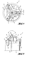
- the embodiment of the drilling tool shown in FIGS. 1 and 2 has one on an elongated shaft adjacent drill head 1, the end face 2 of Cutting is towered, which is made of a cutting material, preferably from a Tungsten carbide.
- the shank is at its end section opposite the drill head for example with a known insertion end for the tool holder a preferably hand-held drill equipped during the Rotation of the drilling tool about its axis A, axial impacts on the rear end of the drilling tool.
- Such drilling devices are, for example, hammer drilling and / or chisel devices of the user.
- the axial strokes are above the elongated Shank and the cutting head 1 equipped with cutting into the to be machined Initiated underground.
- the drilling head 1 of the drilling tool has three head grooves 3, which are in the extend substantially axially and open into at least one discharge groove, which is helical runs on the shaft of the drilling tool and for the removal of the from the underground mined material is provided.
- the head grooves 3 are arranged at the same angular distance from one another.
- the end face 2 of the drill head is in the peripheral area of three circumferential cutting edges 4 protrude, their radial projection over the circumference of the drilling head 1 defines the drilling diameter.
- the contour of the envelope circle b Circumferential cutting 4 is indicated by dashed lines and provided with the reference symbol b.
- the peripheral cutting edges 4 run essentially radially and are plate-shaped Cutting inserts are provided which are in grooves in the end face 2 of the drill head 1, for example, by soldering.
- the three circumferential cutting edges 4, for example are offset in the circumferential direction from the deepest area of the head grooves 3. Out their symmetrical arrangement results in an offset in each case Circumferential direction of about 60 °.
- the centering edges 7, 8, 9 protrude the circumferential cutting edges arranged in the peripheral region of the drilling head 1 in the axial direction Direction.
- the centering cutting edges 7, 8, 9 fall to the circumference of the drill head 1 in such a way that they lie with the peripheral cutting edges 4 on a conical surface.
- the order the centering part 5 is chosen such that the centering cutting edges 7, 8, 9 and Circumferential cutting edges 4 are essentially aligned with each other.
- the Circumferential cutting edges 4 have one in relation to the aligned centering cutting edges 7, 8, 9 radial distance.
- the distance is chosen such that the rotation of the Drilling tool from the free outer edges of the centering 7, 8, 9 described Envelope circle has a radius c, which is preferably about 1 mm to about 8 mm is at least 2 mm smaller than the radius i of the enveloping circle, that of the inner edges the peripheral cutting 4 is described.
- the radially spaced cutting edges 4, 7, 8, 9 can have at least one further cutting edge be provided, the cutting effective area substantially radially over the Gap between the peripheral cutting edges 4 and the centering cutting edges 7, 8, 9 extends.
- the centering part 5 and the peripheral cutting edges 4 can be in the form of separate plates Be designed cutting body.
- the centering part 5 is preferably rotationally symmetrical educated. In the case of a centering part 5 with three centering cutting edges, this is Angle of symmetry then 120 °.
- the peripheral cutting 4 preferably have a plate thickness s which is greater than that Plate thickness t of the centering cutters.
- the foot part of the embedded in the drill head 1 Centering part 5 is between its arms carrying the centering blades 7, 8, 9 Partially circular extensions 11 provided in corresponding recesses in the end face 2 of the drill head 1 are used.
- the foot part 14 of the arms of the Centering part 5 preferably has an essentially semicircular outer contour on.
- the invention was based on the example of a drilling tool with three head grooves and three Centering cutting explained. It is understood that the objects of the invention also include a drilling tool are releasable that only at least one head groove for drilling dust removal and has at least two centering cutting edges, which are in radial extension with the circumferential cutting edges arranged on the periphery of the drill head.
- the number of Centering cutters is at most equal to the number of peripheral cutters.
Landscapes
- Engineering & Computer Science (AREA)
- Mechanical Engineering (AREA)
- Drilling Tools (AREA)
Applications Claiming Priority (2)
| Application Number | Priority Date | Filing Date | Title |
|---|---|---|---|
| DE19827535 | 1998-06-20 | ||
| DE1998127535 DE19827535A1 (de) | 1998-06-20 | 1998-06-20 | Bohrwerkzeug |
Publications (3)
| Publication Number | Publication Date |
|---|---|
| EP0965406A2 true EP0965406A2 (fr) | 1999-12-22 |
| EP0965406A3 EP0965406A3 (fr) | 2002-10-16 |
| EP0965406B1 EP0965406B1 (fr) | 2008-11-19 |
Family
ID=7871507
Family Applications (1)
| Application Number | Title | Priority Date | Filing Date |
|---|---|---|---|
| EP19990810526 Expired - Lifetime EP0965406B1 (fr) | 1998-06-20 | 1999-06-14 | Outil de forage |
Country Status (3)
| Country | Link |
|---|---|
| EP (1) | EP0965406B1 (fr) |
| DE (2) | DE19827535A1 (fr) |
| DK (1) | DK0965406T3 (fr) |
Families Citing this family (2)
| Publication number | Priority date | Publication date | Assignee | Title |
|---|---|---|---|---|
| DE10024433A1 (de) * | 2000-05-19 | 2001-11-29 | Hawera Probst Gmbh | Gesteinsbohrer |
| DE10260113A1 (de) * | 2002-12-19 | 2004-07-01 | Hawera Probst Gmbh | Gesteinsbohrer |
Family Cites Families (5)
| Publication number | Priority date | Publication date | Assignee | Title |
|---|---|---|---|---|
| AT376765B (de) * | 1978-05-16 | 1984-12-27 | Guergen Karlheinz | Auswechselbare bohrkrone fuer einen bei allen gesteinsarten anwendbaren gesteindrehschlagbohrer und bohrhammer |
| DE4012772A1 (de) * | 1990-04-21 | 1991-10-24 | Westa Werkzeugbau | Bohrer fuer bohrhaemmer, insbesondere zum bohren im gestein, beton o. dgl. |
| US5725337A (en) * | 1995-06-16 | 1998-03-10 | Cochran; Donald Paul | Self centering spade drill |
| GB2302664B (en) * | 1995-06-28 | 1998-05-20 | Armeg Ltd | Rotary percussive drill bit |
| DE19605801A1 (de) * | 1996-02-16 | 1997-08-28 | Technotrol Gmbh | Spiralbohrer |
-
1998
- 1998-06-20 DE DE1998127535 patent/DE19827535A1/de not_active Withdrawn
-
1999
- 1999-06-14 EP EP19990810526 patent/EP0965406B1/fr not_active Expired - Lifetime
- 1999-06-14 DK DK99810526T patent/DK0965406T3/da active
- 1999-06-14 DE DE59914904T patent/DE59914904D1/de not_active Expired - Lifetime
Also Published As
| Publication number | Publication date |
|---|---|
| DE19827535A1 (de) | 1999-12-23 |
| EP0965406A3 (fr) | 2002-10-16 |
| EP0965406B1 (fr) | 2008-11-19 |
| DK0965406T3 (da) | 2009-03-23 |
| DE59914904D1 (de) | 2009-01-02 |
Similar Documents
| Publication | Publication Date | Title |
|---|---|---|
| EP0778100B1 (fr) | Foret héliocoidal de percussion | |
| EP0778391B1 (fr) | Perceuse rotative hélicoidale à percussion | |
| EP0884448B1 (fr) | Trépan de roche avec rainures d'évacuation hélicoidales | |
| EP0226537B1 (fr) | Trépan de roche | |
| DE3039632C2 (de) | Drehborhmeißel für Tiefbohrungen | |
| DE60207371T2 (de) | Stumpfvermahlungsgerät | |
| EP0281997B1 (fr) | Fleuret à rocher | |
| EP1302290A1 (fr) | Outil de forage | |
| EP1283935B1 (fr) | Foret a pierre | |
| DE102004022747A1 (de) | Spanwerkzeug mit geometrisch bestimmten Schneiden für Drehantrieb | |
| DE20201300U1 (de) | Bohrkrone | |
| EP1083294A1 (fr) | Outil de forage | |
| DE3020284C2 (fr) | ||
| DE60005046T2 (de) | Rotationsschlagbohrer mit mehreren schneideelementen | |
| EP1083295B1 (fr) | Outil de forage | |
| EP0824626B1 (fr) | Outil de forage | |
| EP3445519B1 (fr) | Foret | |
| DE19709771B4 (de) | Gesteinsbohrer | |
| EP0965406B1 (fr) | Outil de forage | |
| DE10208631A1 (de) | Bohrwerkzeug | |
| EP1083293A1 (fr) | Outil de forage | |
| EP0965405B1 (fr) | Outil de forage | |
| EP0778390B1 (fr) | Perceuse rotative hélicoidale à percussion | |
| EP0607958A1 (fr) | Trépan de roche | |
| EP2519371B1 (fr) | Outil perforateur de roche pour la perforation roto-percutante de béton, de roche, de maçonnerie et de matériaux équivalents |
Legal Events
| Date | Code | Title | Description |
|---|---|---|---|
| PUAI | Public reference made under article 153(3) epc to a published international application that has entered the european phase |
Free format text: ORIGINAL CODE: 0009012 |
|
| AK | Designated contracting states |
Kind code of ref document: A2 Designated state(s): AT BE CH CY DE DK ES FI FR GB GR IE IT LI LU MC NL PT SE |
|
| AX | Request for extension of the european patent |
Free format text: AL;LT;LV;MK;RO;SI |
|
| PUAL | Search report despatched |
Free format text: ORIGINAL CODE: 0009013 |
|
| AK | Designated contracting states |
Kind code of ref document: A3 Designated state(s): AT BE CH CY DE DK ES FI FR GB GR IE IT LI LU MC NL PT SE |
|
| AX | Request for extension of the european patent |
Free format text: AL;LT;LV;MK;RO;SI |
|
| RIC1 | Information provided on ipc code assigned before grant |
Free format text: 7E 21B 10/58 A, 7B 23B 51/02 B |
|
| 17P | Request for examination filed |
Effective date: 20030416 |
|
| AKX | Designation fees paid |
Designated state(s): CH DE DK FR GB LI NL |
|
| 17Q | First examination report despatched |
Effective date: 20070820 |
|
| GRAP | Despatch of communication of intention to grant a patent |
Free format text: ORIGINAL CODE: EPIDOSNIGR1 |
|
| GRAS | Grant fee paid |
Free format text: ORIGINAL CODE: EPIDOSNIGR3 |
|
| GRAA | (expected) grant |
Free format text: ORIGINAL CODE: 0009210 |
|
| AK | Designated contracting states |
Kind code of ref document: B1 Designated state(s): CH DE DK FR GB LI NL |
|
| REG | Reference to a national code |
Ref country code: GB Ref legal event code: FG4D Free format text: NOT ENGLISH |
|
| REG | Reference to a national code |
Ref country code: CH Ref legal event code: EP |
|
| REF | Corresponds to: |
Ref document number: 59914904 Country of ref document: DE Date of ref document: 20090102 Kind code of ref document: P |
|
| REG | Reference to a national code |
Ref country code: DK Ref legal event code: T3 |
|
| PGFP | Annual fee paid to national office [announced via postgrant information from national office to epo] |
Ref country code: NL Payment date: 20090603 Year of fee payment: 11 Ref country code: DK Payment date: 20090615 Year of fee payment: 11 |
|
| PLBE | No opposition filed within time limit |
Free format text: ORIGINAL CODE: 0009261 |
|
| STAA | Information on the status of an ep patent application or granted ep patent |
Free format text: STATUS: NO OPPOSITION FILED WITHIN TIME LIMIT |
|
| 26N | No opposition filed |
Effective date: 20090820 |
|
| PGFP | Annual fee paid to national office [announced via postgrant information from national office to epo] |
Ref country code: CH Payment date: 20090615 Year of fee payment: 11 |
|
| REG | Reference to a national code |
Ref country code: NL Ref legal event code: V1 Effective date: 20110101 |
|
| REG | Reference to a national code |
Ref country code: CH Ref legal event code: PL Ref country code: DK Ref legal event code: EBP |
|
| PG25 | Lapsed in a contracting state [announced via postgrant information from national office to epo] |
Ref country code: LI Free format text: LAPSE BECAUSE OF NON-PAYMENT OF DUE FEES Effective date: 20100630 Ref country code: CH Free format text: LAPSE BECAUSE OF NON-PAYMENT OF DUE FEES Effective date: 20100630 |
|
| PG25 | Lapsed in a contracting state [announced via postgrant information from national office to epo] |
Ref country code: NL Free format text: LAPSE BECAUSE OF NON-PAYMENT OF DUE FEES Effective date: 20110101 |
|
| PG25 | Lapsed in a contracting state [announced via postgrant information from national office to epo] |
Ref country code: DK Free format text: LAPSE BECAUSE OF NON-PAYMENT OF DUE FEES Effective date: 20100630 |
|
| REG | Reference to a national code |
Ref country code: FR Ref legal event code: PLFP Year of fee payment: 18 |
|
| PGFP | Annual fee paid to national office [announced via postgrant information from national office to epo] |
Ref country code: DE Payment date: 20160607 Year of fee payment: 18 Ref country code: GB Payment date: 20160608 Year of fee payment: 18 |
|
| PGFP | Annual fee paid to national office [announced via postgrant information from national office to epo] |
Ref country code: FR Payment date: 20160516 Year of fee payment: 18 |
|
| REG | Reference to a national code |
Ref country code: DE Ref legal event code: R119 Ref document number: 59914904 Country of ref document: DE |
|
| GBPC | Gb: european patent ceased through non-payment of renewal fee |
Effective date: 20170614 |
|
| REG | Reference to a national code |
Ref country code: FR Ref legal event code: ST Effective date: 20180228 |
|
| PG25 | Lapsed in a contracting state [announced via postgrant information from national office to epo] |
Ref country code: DE Free format text: LAPSE BECAUSE OF NON-PAYMENT OF DUE FEES Effective date: 20180103 Ref country code: GB Free format text: LAPSE BECAUSE OF NON-PAYMENT OF DUE FEES Effective date: 20170614 |
|
| PG25 | Lapsed in a contracting state [announced via postgrant information from national office to epo] |
Ref country code: FR Free format text: LAPSE BECAUSE OF NON-PAYMENT OF DUE FEES Effective date: 20170630 |