EP0965414A2 - Werkstückträger - Google Patents
Werkstückträger Download PDFInfo
- Publication number
- EP0965414A2 EP0965414A2 EP99110449A EP99110449A EP0965414A2 EP 0965414 A2 EP0965414 A2 EP 0965414A2 EP 99110449 A EP99110449 A EP 99110449A EP 99110449 A EP99110449 A EP 99110449A EP 0965414 A2 EP0965414 A2 EP 0965414A2
- Authority
- EP
- European Patent Office
- Prior art keywords
- workpiece carrier
- belt conveyor
- energy
- friction
- spring
- Prior art date
- Legal status (The legal status is an assumption and is not a legal conclusion. Google has not performed a legal analysis and makes no representation as to the accuracy of the status listed.)
- Granted
Links
- 238000004146 energy storage Methods 0.000 claims description 13
- 230000008878 coupling Effects 0.000 claims description 10
- 238000010168 coupling process Methods 0.000 claims description 10
- 238000005859 coupling reaction Methods 0.000 claims description 10
- 230000001133 acceleration Effects 0.000 claims description 6
- 239000000969 carrier Substances 0.000 description 4
- 238000004519 manufacturing process Methods 0.000 description 4
- 230000005540 biological transmission Effects 0.000 description 1
- 238000011161 development Methods 0.000 description 1
- 230000018109 developmental process Effects 0.000 description 1
- 230000003292 diminished effect Effects 0.000 description 1
- 238000000034 method Methods 0.000 description 1
Images

Classifications
-
- B—PERFORMING OPERATIONS; TRANSPORTING
- B65—CONVEYING; PACKING; STORING; HANDLING THIN OR FILAMENTARY MATERIAL
- B65G—TRANSPORT OR STORAGE DEVICES, e.g. CONVEYORS FOR LOADING OR TIPPING, SHOP CONVEYOR SYSTEMS OR PNEUMATIC TUBE CONVEYORS
- B65G47/00—Article or material-handling devices associated with conveyors; Methods employing such devices
- B65G47/74—Feeding, transfer, or discharging devices of particular kinds or types
- B65G47/88—Separating or stopping elements, e.g. fingers
- B65G47/8807—Separating or stopping elements, e.g. fingers with one stop
- B65G47/8815—Reciprocating stop, moving up or down in the path of the article
-
- B—PERFORMING OPERATIONS; TRANSPORTING
- B23—MACHINE TOOLS; METAL-WORKING NOT OTHERWISE PROVIDED FOR
- B23Q—DETAILS, COMPONENTS, OR ACCESSORIES FOR MACHINE TOOLS, e.g. ARRANGEMENTS FOR COPYING OR CONTROLLING; MACHINE TOOLS IN GENERAL CHARACTERISED BY THE CONSTRUCTION OF PARTICULAR DETAILS OR COMPONENTS; COMBINATIONS OR ASSOCIATIONS OF METAL-WORKING MACHINES, NOT DIRECTED TO A PARTICULAR RESULT
- B23Q7/00—Arrangements for handling work specially combined with or arranged in, or specially adapted for use in connection with, machine tools, e.g. for conveying, loading, positioning, discharging, sorting
- B23Q7/14—Arrangements for handling work specially combined with or arranged in, or specially adapted for use in connection with, machine tools, e.g. for conveying, loading, positioning, discharging, sorting co-ordinated in production lines
-
- B—PERFORMING OPERATIONS; TRANSPORTING
- B65—CONVEYING; PACKING; STORING; HANDLING THIN OR FILAMENTARY MATERIAL
- B65G—TRANSPORT OR STORAGE DEVICES, e.g. CONVEYORS FOR LOADING OR TIPPING, SHOP CONVEYOR SYSTEMS OR PNEUMATIC TUBE CONVEYORS
- B65G17/00—Conveyors having an endless traction element, e.g. a chain, transmitting movement to a continuous or substantially-continuous load-carrying surface or to a series of individual load-carriers; Endless-chain conveyors in which the chains form the load-carrying surface
- B65G17/002—Conveyors having an endless traction element, e.g. a chain, transmitting movement to a continuous or substantially-continuous load-carrying surface or to a series of individual load-carriers; Endless-chain conveyors in which the chains form the load-carrying surface comprising load carriers resting on the traction element
-
- B—PERFORMING OPERATIONS; TRANSPORTING
- B65—CONVEYING; PACKING; STORING; HANDLING THIN OR FILAMENTARY MATERIAL
- B65G—TRANSPORT OR STORAGE DEVICES, e.g. CONVEYORS FOR LOADING OR TIPPING, SHOP CONVEYOR SYSTEMS OR PNEUMATIC TUBE CONVEYORS
- B65G2201/00—Indexing codes relating to handling devices, e.g. conveyors, characterised by the type of product or load being conveyed or handled
- B65G2201/02—Articles
-
- B—PERFORMING OPERATIONS; TRANSPORTING
- B65—CONVEYING; PACKING; STORING; HANDLING THIN OR FILAMENTARY MATERIAL
- B65G—TRANSPORT OR STORAGE DEVICES, e.g. CONVEYORS FOR LOADING OR TIPPING, SHOP CONVEYOR SYSTEMS OR PNEUMATIC TUBE CONVEYORS
- B65G2205/00—Stopping elements used in conveyors to stop articles or arrays of articles
- B65G2205/04—Stopping elements used in conveyors to stop articles or arrays of articles where the stop device is not adaptable
Definitions
- the invention relates to a workpiece carrier according to the Genus of the main claim.
- a workpiece carrier for transport through a belt conveyor, in particular a double belt conveyor known.
- Such workpiece carriers are used in industrial Assembly and manufacturing systems used.
- the Workpiece carrier lies on the belt conveyor and is over a frictional connection between the workpiece carrier and the Belt conveyor transported.
- In front of processing stations or Transfer points to other belt conveyors become these Workpiece carrier brought to a standstill. This happens in usually via stoppers, which have a movable cam have in the path of movement of the workpiece carrier can be driven and this stops it.
- the Workpiece carrier stopped the belt conveyor slides continue under the workpiece carrier. Is the Workpiece carrier no longer braked, i.e.
- the cam of the Stoppers clears the way, so the workpiece carrier needs some time to - through the belt conveyor funded - the processing station or the transfer point to reach. By a certain sliding of the belt conveyor under the workpiece carrier during start-up can still additional time will be lost. In any case, it increases total cycle time of the affected assembly or Manufacturing plant.
- the workpiece carrier according to the invention with the characteristic has the advantage that when starting, i.e. when the workpiece carrier is no longer is braked, less time is lost.
- a special one simple structure results when a spring over a Coupling element by the conveyor movement of the belt conveyor is excited.
- By covering with an anisotropic Friction behavior can be used optimally.
- the friction coefficients of the Improve coupling elements and the belt conveyor. Are the Pressure springs dimensioned so that the workpiece carrier Belt conveyor only touches the energy storage, so all undesired friction can be eliminated.
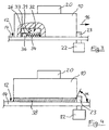
- a workpiece carrier 10 is shown in FIG a first belt conveyor 12 rests, of which only one Segment is shown.
- the belt conveyor 12 has two parallel straps 14, which is one so-called double belt conveyor.
- operational transport direction 16 of the belt conveyor 12 specified. Is at right angles to the first belt conveyor 12 a second belt conveyor 18 with dashed lines indicated.
- the workpiece carrier 10 can also along this second belt conveyor 18 can be transported.
- On the workpiece carrier 10 is symbolically a workpiece 20 shown, there being also several workpieces 20 can.
- In the transport direction 16 is in front of the workpiece carrier 10 a stopper 22 with a movable cam 23 arranged. The stopper 22 is used to stop the Workpiece carrier 10, but later in more detail is received.
- the Workpiece carrier 10 at least one energy storage device 24 having.
- ever Transport direction 16 of the workpiece carrier 10 at least two Energy storage 24 are provided.
- FIG. 2 is in a breakout from the workpiece carrier 10 shows a recess 26.
- the energy store 24 has a rotating as a coupling element arranged friction wheel 28, which with the belt conveyor 12, 18th is in operative connection.
- the energy store 24 has a spring designed as a spiral spring 30, which is in operative connection with the friction wheel 28, i.e. that the coil spring 30 can be tensioned by the friction wheel 28.
- in the Center of the coil spring 30 and on the workpiece carrier 10 is a helical pressure spring 31 arranged such that the energy store 24 through the pressure spring 31 to the Belt conveyor 12, 18 can be pressed, whereby the friction between the friction wheel 28 and the belt 14 can be raised.
- the transport of the workpiece carrier 10 on the steady conveyor belt conveyor 12, 18 is due to the cam 23rd of the stopper 22, which is in the conveyor path of the workpiece carrier 10 is shown in a stopped manner.
- a pneumatic actuation of the stopper 22, for example is the cam 23 under one by the straps 14 of the Belt conveyor 12, 18 formed transport plane movable, with which the workpiece carrier 10 can be conveyed further.
- the workpiece carrier 10 for Transport by the belt conveyor 12, 18 the same Speed like the belt conveyor 12, 18.
- the Time, however, in which, for example, the workpiece carrier 10 in has reached the processing station, is lost because in no processing can take place during this time, which means The cycle time of the entire production system increases.
- the workpiece carrier 10 is straight in a waiting position, i.e. his ride on the Belt conveyor 14, 18 through the cam 23 of the stopper 22nd stopped, so is the speed of the workpiece carrier 10 equals zero.
- the speed of the belt 14 of the Belt conveyor 12, 18 remains unchanged, however. Is moving the belt 14 in the indicated in Figure 2 Transport direction 16, i.e. to the right in the drawing, see above is the friction wheel 28 by the conveyor movement in Turned counterclockwise. By this rotation, however the coil spring 30 is tensioned, i.e. it takes energy on. So that the friction wheel 28 when the coil spring 30 is tensioned not too strongly against the transport direction 16 of the belt 14 rotated, the friction wheel 28 by the pressure spring 31st pressed against the belt 14.
- FIG. 2 shows the friction wheel 28 in Turned clockwise.
- the workpiece carrier 10 thus experiences an additional acceleration towards the Transport direction 16. This is advantageous Acceleration so great that the speed of the Workpiece carrier 10 is larger than that of the belt conveyor 12. In this way, the cycle time of a manufacturing plant be greatly reduced.
- the principle for reducing cycle times is based on the fact that one with the belt conveyor 12, 18 braked workpiece carrier 10 energy in the Workpiece carrier 10 is transferable. With one versus Belt conveyor 12, 18 no longer braked workpiece carriers 10 this absorbed energy is released again, so that the workpiece carrier 10 an additional acceleration experiences. The energy is transferred through the conveying movement of the belt conveyor 12, 18.
- the friction wheel 28 functions as an energy store the coil spring 30.
- a second modified energy store 32 shown in a recess 26 of the workpiece carrier 10 from the figure 3 .
- a recording 33 by a Pressure spring 31 is pressed against the belt conveyor 12, 18 and which is open on the side of the belt 14 is one in Helical spring 34 acting essentially parallel to the belt 14 and a coupling element designed as a friction shoe 36 arranged.
- the receptacle 33 is in the recess 26 in substantially perpendicular to the transport direction 16 of the Belt conveyor 12, 18 movably arranged.
- the friction shoe 36 is in the direction of Transport direction 16 shifted by the belt 14.
- the coil spring 34 can be tensioned, i.e. that by doing so Absorbs energy.
- the workpiece carrier 10 is no longer braked, the coil spring 34 relaxes and gives the absorbed energy again, whereby the Workpiece carrier 10 opposite the belt conveyor 12, 18th is accelerated.
- Elastic extensions in the form of bristles 38 are arranged on the workpiece carrier 10 from FIG. 4 and cooperate with the belt conveyor 12, 18. Starting from the transport direction 16 of the belt conveyor 12, 18 to the bristles 38, an angle ⁇ is included which is less than 90 °.
- the bristles 38 thus provide a covering between the workpiece carrier 10 and the belt conveyor 12, 18, which has a first friction coefficient ⁇ 1 at a speed of the workpiece carrier 10 that is lower than the speed of the belt conveyor 12, 18. Due to the higher speed of the belts 14 of the belt conveyor 12, 18 than the workpiece carrier 10, the ends of the bristles are bent in the direction of the transport direction 16. If the movement of the workpiece carrier 10 is released or no longer braked, the bristles 38 bend back into the starting position due to their elastic behavior.
- the workpiece carrier 10 experiences an additional acceleration.
- the speed of the workpiece carrier 10 is higher than the speed of the belt conveyor 12, 18.
- the covering has a second coefficient of friction ⁇ 2 , which is lower than the first coefficient of friction ⁇ 1 , which is why this is a anisotropic friction behavior.
- the bristles 38 can thus also be used as an energy store. Ideally, however, the bristles 38 can be used in combination with the energy stores 24 or 32.
Landscapes
- Engineering & Computer Science (AREA)
- Mechanical Engineering (AREA)
- Attitude Control For Articles On Conveyors (AREA)
- Structure Of Belt Conveyors (AREA)
- Braking Arrangements (AREA)
Abstract
Description
Claims (10)
- Werkstückträger (10) für den Transport durch wenigstens einen Gurtförderer (12, 18), insbesondere einen Doppelgurtförderer, dadurch gekennzeichnet, daß der Werkstückträger (10) mindestens einen Energiespeicher (24, 32, 38) aufweist, in den bei einem gegenüber dem Gurtförderer (12, 18) abgebremsten Werkstückträger (10) Energie übertragbar ist und der bei einem gegenüber dem Gurtförderer (12, 18) nicht mehr abgebremsten Werkstückträger (10) die aufgenommene Energie abgibt, so daß der Werkstückträger (10) eine zusätzliche Beschleunigung erfährt.
- Werkstückträger (10) nach Anspruch 1, dadurch gekennzeichnet, daß der mindestens eine Energiespeicher (24, 32, 38) wenigstens ein Koppelelement (28, 36) aufweist, das mit dem Gurtförderer (12, 18) in Wirkverbindung steht und daß die Energie durch die Förderbewegung des Gurtförderers (12, 18) in den mindestens einen Energiespeicher (24, 32) übertragbar ist.
- Werkstückträger (10) nach Anspruch 2, dadurch gekennzeichnet, daß der mindestens eine Energiespeicher (24, 32) wenigstens eine Feder aufweist, welche mit dem wenigstens einen Koppelelement (28, 36) in Wirkverbindung steht und welche die Energie aufnimmt und abgibt.
- Werkstückträger (10) nach Anspruch 3, dadurch gekennzeichnet, daß das wenigstens eine Koppelelement ein drehbar angeordnetes Reibrad (28) ist und daß die wenigstens eine Feder eine Spiralfeder (30) ist, die durch das Reibrad (28) spannbar ist.
- Werkstückträger (10) nach Anspruch 3, dadurch gekennzeichnet, daß das wenigstens eine Koppelelement ein Reibschuh (36) ist, und daß die wenigstens eine Feder eine Schraubenfeder (34) ist, die durch den vom Gurtförderer (12, 18) verschiebbaren Reibschuh (36) spannbar ist.
- Werkstückträger (10) nach einem der Ansprüche 1 bis 5, dadurch gekennzeichnet, daß zwischen dem Werkstückträger (10) und dem wenigstens einen Gurtförderer (12, 18) ein Belag (38) vorgesehen ist, der bei einer Geschwindigkeit des Werkstückträgers (10), die niedriger ist, als die Geschwindigkeit des wenigstens einen Gurtförderers (12, 18) einen ersten Reibungskoeffizienten (µ1) aufweist und der bei einer Geschwindigkeit des Werkstückträgers (10), die höher ist, als die Geschwindigkeit des wenigstens einen Gurtförderers (12, 18), einen zweiten Reibungskoeffizienten (µ2) aufweist, der niedriger ist als der erste Reibungskoeffizient (µ1).
- Werkstückträger (10) nach einem der Ansprüche 1 bis 6, dadurch gekennzeichnet, daß an dem Werkstückträger (10) elastische Fortsätze (38) angeordnet sind, die mit dem Gurtförderer (12, 18) zusammenwirken, wobei ein Winkel (α) zwischen den elastischen Fortsätzen (38) und der Transportrichtung (16) des wenigstens einen Gurtförderers (12, 18) kleiner als 90° ist.
- Werkstückträger (10) nach einem der Ansprüche 1 bis 7, dadurch gekennzeichnet, daß der mindestens eine Energiespeicher (24) durch wenigstens eine Andrückfeder (31) an den Gurtförderer (12, 18) drückbar ist.
- Werkstückträger (10) nach einem der Ansprüche 1 bis 8, dadurch gekennzeichnet, daß je Transportrichtung (16) des Werkstückträgers (10) mindestens zwei Energiespeicher (24, 32, 38) vorgesehen sind.
- Werkstückträger (10) nach einem der Ansprüche 1 bis 9, dadurch gekennzeichnet, daß je Transportrichtung (16) des Werkstückträgers (10) vier Energiespeicher (24, 32) vorgesehen sind, und daß die Summe der Federkräfte der Andrückfedern (31) der je Transportrichtung (16) vorgesehenen vier Energiespeicher (24) größer ist als die vom Werkstückträger (10) ausgeübte betriebsmäßige Gewichtskraft.
Applications Claiming Priority (2)
| Application Number | Priority Date | Filing Date | Title |
|---|---|---|---|
| DE19826863 | 1998-06-17 | ||
| DE19826863A DE19826863B4 (de) | 1998-06-17 | 1998-06-17 | Werkstückträger |
Publications (3)
| Publication Number | Publication Date |
|---|---|
| EP0965414A2 true EP0965414A2 (de) | 1999-12-22 |
| EP0965414A3 EP0965414A3 (de) | 2001-05-02 |
| EP0965414B1 EP0965414B1 (de) | 2004-04-07 |
Family
ID=7871086
Family Applications (1)
| Application Number | Title | Priority Date | Filing Date |
|---|---|---|---|
| EP99110449A Expired - Lifetime EP0965414B1 (de) | 1998-06-17 | 1999-05-29 | Werkstückträger |
Country Status (4)
| Country | Link |
|---|---|
| US (1) | US6371273B1 (de) |
| EP (1) | EP0965414B1 (de) |
| DE (2) | DE19826863B4 (de) |
| ES (1) | ES2219952T3 (de) |
Families Citing this family (1)
| Publication number | Priority date | Publication date | Assignee | Title |
|---|---|---|---|---|
| DE10316941A1 (de) | 2003-04-12 | 2004-11-11 | Arzneimittel Gmbh Apotheker Vetter & Co. Ravensburg | Transporteinrichtung |
Citations (1)
| Publication number | Priority date | Publication date | Assignee | Title |
|---|---|---|---|---|
| EP0037361B1 (de) | 1980-03-29 | 1985-06-26 | Robert Bosch Gmbh | Werkstückträger für Fertigungs- und Montagestrassen |
Family Cites Families (16)
| Publication number | Priority date | Publication date | Assignee | Title |
|---|---|---|---|---|
| GB601719A (en) * | 1946-06-04 | 1948-05-11 | King Ltd Geo W | Improvements in or relating to conveyor systems |
| BE639931A (de) * | 1963-01-14 | |||
| DE1256153B (de) * | 1966-07-27 | 1967-12-07 | Siemens Ag | Foerderanlage, insbesondere Kastenfoerderanlage, zur Befoerderung von Foerderbehaeltern in Fahrrinnen |
| CH566249A5 (de) * | 1974-05-30 | 1975-09-15 | Micafil Ag | |
| US4509429A (en) * | 1980-03-06 | 1985-04-09 | Broqueville Axel De | Transportation system utilizing a stretchable train of cars and stretchable bandconveyors |
| DE3633702A1 (de) * | 1986-10-03 | 1988-04-14 | Otmar Fahrion | Foerdereinrichtung |
| CH680285A5 (de) * | 1987-10-02 | 1992-07-31 | Ferag Ag | |
| DK174001B1 (da) * | 1987-11-13 | 2002-04-08 | Vortex Systems Srl | Apparat til transport og gruppering af emner |
| DD270508A1 (de) * | 1988-04-11 | 1989-08-02 | Ingbuero Fuer Rationalisierung | Vorrichtung zum transportieren von lastenrollern in einem haengetransportsystem |
| FR2630092B1 (fr) * | 1988-04-14 | 1993-03-26 | Sgie Ind Sa | Navette comportant un dispositif de freinage, associee a un convoyeur en pente pour l'accumulation de navettes |
| DE3926755A1 (de) * | 1989-08-12 | 1991-02-14 | Lanco Ag | Foerderanlage fuer werkstuecktraeger u. dergl. |
| DE4320706C1 (de) * | 1993-06-23 | 1994-10-06 | Protech Automation Gmbh | Duplexförderer |
| EP0633212B1 (de) * | 1993-07-07 | 1997-03-26 | Ferag AG | Endlos umlaufende Stückgut-Transportvorrichtung mit individuellen Transportorganen |
| DE9416115U1 (de) * | 1994-10-06 | 1995-08-03 | F+S Automationstechnik GmbH, 74229 Oedheim | Paletten-Stauförderer |
| DE19517276C2 (de) * | 1995-05-11 | 1999-01-14 | Hoyer Montagetechnik Gmbh | Transfersystem für taktungebundenen Betrieb |
| US6244451B1 (en) * | 1999-09-24 | 2001-06-12 | Conveyor Technology Group, Inc. | Shock absorbing tow bar for trolley-type conveyor systems |
-
1998
- 1998-06-17 DE DE19826863A patent/DE19826863B4/de not_active Expired - Fee Related
-
1999
- 1999-05-29 ES ES99110449T patent/ES2219952T3/es not_active Expired - Lifetime
- 1999-05-29 EP EP99110449A patent/EP0965414B1/de not_active Expired - Lifetime
- 1999-05-29 DE DE59909083T patent/DE59909083D1/de not_active Expired - Lifetime
- 1999-06-16 US US09/334,293 patent/US6371273B1/en not_active Expired - Fee Related
Patent Citations (1)
| Publication number | Priority date | Publication date | Assignee | Title |
|---|---|---|---|---|
| EP0037361B1 (de) | 1980-03-29 | 1985-06-26 | Robert Bosch Gmbh | Werkstückträger für Fertigungs- und Montagestrassen |
Also Published As
| Publication number | Publication date |
|---|---|
| EP0965414A3 (de) | 2001-05-02 |
| DE19826863A1 (de) | 1999-12-23 |
| DE19826863B4 (de) | 2004-11-25 |
| DE59909083D1 (de) | 2004-05-13 |
| ES2219952T3 (es) | 2004-12-01 |
| US6371273B1 (en) | 2002-04-16 |
| EP0965414B1 (de) | 2004-04-07 |
Similar Documents
| Publication | Publication Date | Title |
|---|---|---|
| CH620652A5 (de) | ||
| DE102011112317B3 (de) | Wendevorrichtung für Identifikationsgegenstände | |
| DE102021209985A1 (de) | Handhabungssystem zur automatischen Übergabe und Vereinzelung von Ladungsträgern | |
| DE2618439B1 (de) | Transporteinrichtung fuer die auswertung von identifizierungskarten | |
| DE60301201T2 (de) | Vorrichtung zum Bewegen von Produkten | |
| CH657083A5 (de) | Vorrichtung an einem koordinatentisch einer bearbeitungsmaschine fuer einen schlittenantrieb. | |
| DE3445865C2 (de) | ||
| EP0965414B1 (de) | Werkstückträger | |
| DE3886224T2 (de) | Vorrichtung und verfahren zur positionierung von verpackungen. | |
| DE19517276A1 (de) | Transfersystem für taktungebundenen Betrieb | |
| DE102020114391B4 (de) | Förderanlagenvorrichtung und Förderanlage zu einem geordneten Fördern von länglich erstreckten Objekten wie Ampullen, Karpulen, Spritzen, Pipetten, Vials oder dergleichen | |
| DE202017106660U1 (de) | Behälterbehandlungsmaschine und Transporteinrichtung für Behälter | |
| DE2209483A1 (de) | Verfahren und einrichtung zum vereinzeln von aufzeichnungstraegern | |
| DE3877128T2 (de) | Vorrichtung zum verschieben von spulentransporttraegern, die aus einer scheibenartigen grundplatte und einem mittigen zapfen bestehen, in einer spinnerei. | |
| WO1997009131A1 (de) | Sortiereinrichtung, insbesondere für postgut | |
| DE60318739T2 (de) | Verfahren und vorrichtung zur handhabung von walzen | |
| DE2605326C3 (de) | Kupplungsvorrichtung zum Kuppeln eines drehbaren antreibenden Gliedes mit einem drehbaren angetriebenen Glied | |
| DE2011251A1 (de) | Stapeleinrichtung | |
| DE2352424A1 (de) | Foerderer zum transport von zeitungsstoessen bzw. -paketen | |
| DE69600631T2 (de) | Förderer zur schrittweisen Förderung von Produkten zwischen aufeinanderfolgenden Bearbeitungsmaschinen | |
| DE3813080A1 (de) | Speicher mit einem endlos-speicherelement | |
| DE19711761C2 (de) | Wendevorrichtung für im wesentlichen flache Gegenstände | |
| DE4023003A1 (de) | Positionierungsvorrichtung mit greifwerkzeugen | |
| DE4243986C2 (de) | Vorrichtung zum Ändern der Bewegungsrichtung von flachem, rechteckigen Blattgut | |
| DE3211371C2 (de) | Vorrichtung zum Vereinzeln des jeweils obersten Blattes eines Stapels von blattförmigem Gut |
Legal Events
| Date | Code | Title | Description |
|---|---|---|---|
| PUAI | Public reference made under article 153(3) epc to a published international application that has entered the european phase |
Free format text: ORIGINAL CODE: 0009012 |
|
| AK | Designated contracting states |
Kind code of ref document: A2 Designated state(s): CH DE ES FR GB IT LI SE |
|
| AX | Request for extension of the european patent |
Free format text: AL;LT;LV;MK;RO;SI |
|
| PUAL | Search report despatched |
Free format text: ORIGINAL CODE: 0009013 |
|
| AK | Designated contracting states |
Kind code of ref document: A3 Designated state(s): AT BE CH CY DE DK ES FI FR GB GR IE IT LI LU MC NL PT SE |
|
| AX | Request for extension of the european patent |
Free format text: AL;LT;LV;MK;RO;SI |
|
| 17P | Request for examination filed |
Effective date: 20011102 |
|
| AKX | Designation fees paid |
Free format text: CH DE ES FR GB IT LI SE |
|
| GRAP | Despatch of communication of intention to grant a patent |
Free format text: ORIGINAL CODE: EPIDOSNIGR1 |
|
| GRAS | Grant fee paid |
Free format text: ORIGINAL CODE: EPIDOSNIGR3 |
|
| GRAA | (expected) grant |
Free format text: ORIGINAL CODE: 0009210 |
|
| AK | Designated contracting states |
Kind code of ref document: B1 Designated state(s): CH DE ES FR GB IT LI SE |
|
| REG | Reference to a national code |
Ref country code: GB Ref legal event code: FG4D Free format text: NOT ENGLISH |
|
| REG | Reference to a national code |
Ref country code: CH Ref legal event code: NV Representative=s name: SCINTILLA AG, DIREKTION Ref country code: CH Ref legal event code: EP |
|
| PGFP | Annual fee paid to national office [announced via postgrant information from national office to epo] |
Ref country code: GB Payment date: 20040510 Year of fee payment: 6 |
|
| REF | Corresponds to: |
Ref document number: 59909083 Country of ref document: DE Date of ref document: 20040513 Kind code of ref document: P |
|
| PGFP | Annual fee paid to national office [announced via postgrant information from national office to epo] |
Ref country code: CH Payment date: 20040524 Year of fee payment: 6 |
|
| REG | Reference to a national code |
Ref country code: SE Ref legal event code: TRGR |
|
| GBT | Gb: translation of ep patent filed (gb section 77(6)(a)/1977) |
Effective date: 20040708 |
|
| REG | Reference to a national code |
Ref country code: ES Ref legal event code: FG2A Ref document number: 2219952 Country of ref document: ES Kind code of ref document: T3 |
|
| ET | Fr: translation filed | ||
| PLBE | No opposition filed within time limit |
Free format text: ORIGINAL CODE: 0009261 |
|
| STAA | Information on the status of an ep patent application or granted ep patent |
Free format text: STATUS: NO OPPOSITION FILED WITHIN TIME LIMIT |
|
| 26N | No opposition filed |
Effective date: 20050110 |
|
| PG25 | Lapsed in a contracting state [announced via postgrant information from national office to epo] |
Ref country code: GB Free format text: LAPSE BECAUSE OF NON-PAYMENT OF DUE FEES Effective date: 20050529 |
|
| PG25 | Lapsed in a contracting state [announced via postgrant information from national office to epo] |
Ref country code: LI Free format text: LAPSE BECAUSE OF NON-PAYMENT OF DUE FEES Effective date: 20050531 Ref country code: CH Free format text: LAPSE BECAUSE OF NON-PAYMENT OF DUE FEES Effective date: 20050531 |
|
| REG | Reference to a national code |
Ref country code: CH Ref legal event code: PL |
|
| GBPC | Gb: european patent ceased through non-payment of renewal fee |
Effective date: 20050529 |
|
| PGFP | Annual fee paid to national office [announced via postgrant information from national office to epo] |
Ref country code: SE Payment date: 20091222 Year of fee payment: 12 |
|
| PGFP | Annual fee paid to national office [announced via postgrant information from national office to epo] |
Ref country code: FR Payment date: 20100608 Year of fee payment: 12 Ref country code: ES Payment date: 20100520 Year of fee payment: 12 |
|
| PGFP | Annual fee paid to national office [announced via postgrant information from national office to epo] |
Ref country code: IT Payment date: 20100526 Year of fee payment: 12 |
|
| PGFP | Annual fee paid to national office [announced via postgrant information from national office to epo] |
Ref country code: DE Payment date: 20110726 Year of fee payment: 13 |
|
| REG | Reference to a national code |
Ref country code: SE Ref legal event code: EUG |
|
| REG | Reference to a national code |
Ref country code: FR Ref legal event code: ST Effective date: 20120131 |
|
| PG25 | Lapsed in a contracting state [announced via postgrant information from national office to epo] |
Ref country code: IT Free format text: LAPSE BECAUSE OF NON-PAYMENT OF DUE FEES Effective date: 20110529 |
|
| PG25 | Lapsed in a contracting state [announced via postgrant information from national office to epo] |
Ref country code: FR Free format text: LAPSE BECAUSE OF NON-PAYMENT OF DUE FEES Effective date: 20110531 |
|
| REG | Reference to a national code |
Ref country code: DE Ref legal event code: R119 Ref document number: 59909083 Country of ref document: DE Effective date: 20121201 |
|
| REG | Reference to a national code |
Ref country code: ES Ref legal event code: FD2A Effective date: 20130404 |
|
| PG25 | Lapsed in a contracting state [announced via postgrant information from national office to epo] |
Ref country code: ES Free format text: LAPSE BECAUSE OF NON-PAYMENT OF DUE FEES Effective date: 20110530 Ref country code: SE Free format text: LAPSE BECAUSE OF NON-PAYMENT OF DUE FEES Effective date: 20110530 |
|
| PG25 | Lapsed in a contracting state [announced via postgrant information from national office to epo] |
Ref country code: DE Free format text: LAPSE BECAUSE OF NON-PAYMENT OF DUE FEES Effective date: 20121201 |