EP0965458B1 - Farbbandanordnung und seine Verwendung in einem Wärmübertragungsdrucker - Google Patents
Farbbandanordnung und seine Verwendung in einem Wärmübertragungsdrucker Download PDFInfo
- Publication number
- EP0965458B1 EP0965458B1 EP99304492A EP99304492A EP0965458B1 EP 0965458 B1 EP0965458 B1 EP 0965458B1 EP 99304492 A EP99304492 A EP 99304492A EP 99304492 A EP99304492 A EP 99304492A EP 0965458 B1 EP0965458 B1 EP 0965458B1
- Authority
- EP
- European Patent Office
- Prior art keywords
- ink
- ribbon
- ink ribbon
- printing
- shorter
- Prior art date
- Legal status (The legal status is an assumption and is not a legal conclusion. Google has not performed a legal analysis and makes no representation as to the accuracy of the status listed.)
- Expired - Lifetime
Links
Images


Classifications
-
- B—PERFORMING OPERATIONS; TRANSPORTING
- B41—PRINTING; LINING MACHINES; TYPEWRITERS; STAMPS
- B41J—TYPEWRITERS; SELECTIVE PRINTING MECHANISMS, i.e. MECHANISMS PRINTING OTHERWISE THAN FROM A FORME; CORRECTION OF TYPOGRAPHICAL ERRORS
- B41J35/00—Other apparatus or arrangements associated with, or incorporated in, ink-ribbon mechanisms
- B41J35/36—Alarms, indicators, or feed disabling devices responsive to ink ribbon breakage or exhaustion
-
- B—PERFORMING OPERATIONS; TRANSPORTING
- B41—PRINTING; LINING MACHINES; TYPEWRITERS; STAMPS
- B41J—TYPEWRITERS; SELECTIVE PRINTING MECHANISMS, i.e. MECHANISMS PRINTING OTHERWISE THAN FROM A FORME; CORRECTION OF TYPOGRAPHICAL ERRORS
- B41J31/00—Ink ribbons; Renovating or testing ink ribbons
-
- B—PERFORMING OPERATIONS; TRANSPORTING
- B41—PRINTING; LINING MACHINES; TYPEWRITERS; STAMPS
- B41J—TYPEWRITERS; SELECTIVE PRINTING MECHANISMS, i.e. MECHANISMS PRINTING OTHERWISE THAN FROM A FORME; CORRECTION OF TYPOGRAPHICAL ERRORS
- B41J35/00—Other apparatus or arrangements associated with, or incorporated in, ink-ribbon mechanisms
- B41J35/22—Mechanisms permitting the selective use of a plurality of ink ribbons
Definitions
- the present invention relates to an ink ribbon assembly comprising a plurality of ink ribbons, and to a thermal transfer printer using such ink ribbon assembly.
- the present invention relates to an ink ribbon assembly and a thermal transfer printer using the ink ribbon assembly, suitable to lap-print an image with a color ink on a foundation or undercoat already printed, and print an overcoat on the printed image with a clear ink.
- the thermal transfer printer is conventionally used in a wider field for output units such as a computer, a word processor and the like by reasons of a higher printing quality, a lower noise, a lower cost and an easy maintenance.
- a printing process which comprises printing a foundation or undercoat with a clear ink or a white ink for the purpose of previously smoothening the surface of a paper sheet, or treating the surface of a paper sheet to provide a state in which the ink is easily transferred, prior to the printing of an image with an ink of a predetermined color; lap-printing the image on the undercoat with the ink of a predetermined color; and further conducting a lap-printing on an upper surface of the printed image with a clear ink in order to improve the slidability.
- Thermal transfer printers using such a printing process which have been proposed include a so-called auto-changed type thermal transfer printer including a plurality of ribbon cassettes which have ink ribbons (each of which is one of ink films) accommodated therein and retained at a location opposed to a carriage, so that a desired ribbon cassette is selectively replaced automatically by another one depending on the printing, whereby the printing is carried out, see GB-A-2 314 042.
- the printing of the undercoat is intended to improve the printing of the image
- the overlap printing of an overcoat is intended to protect the code which is the printed image.
- an object of the present invention to provide an ink ribbon assembly and a thermal transfer printer using such an ink ribbon, wherein the printing of the image with the predetermined-color ink is feasible necessarily to the terminal end of a printing area, so that the ink ribbon does not reach its end in the middle of the printing.
- an ink ribbon assembly for use in a thermal transfer printer which uses a plurality of ink ribbons and conducts lap-printings by using the ink ribbons in a predetermined order, wherein at least one ink ribbon less influencing the printing accuracy is shorter in length than the other ink ribbons, the shorter ink ribbon having a terminal end mark formed at its terminal end.
- the other ink ribbons have finished the printing of the printing area, because they are longer in length than the at least one shorter ink ribbon, and hence, joints cannot be produced in the printing carried out by the longer ink ribbons.
- the shorter ink ribbon is an ink ribbon for use in the printing of an uppermost layer.
- the ink ribbon for use in the printing of the uppermost layer is an ink ribbon for an overcoat having a dear ink.
- the shorter ink ribbon is an ink ribbon for use in the printing of a lowermost layer.
- the lowermost layer less influences the printing accuracy. Therefore, when the ribbon end is detected in the middle of the printing of one printing area and the ink ribbon is replaced by new one to conduct the printing, the printing is feasible, even if a gap or a joint such as an overlapped portion is produced between the printing area printed with the unreplaced ink ribbon and the printing area printed with the new ink ribbon.
- the overlapped portion may be provided rather than provision of the gap at the joint. In this case, it is particularly preferable that the length of the overlapped portion is on the order of 1 mm.
- the shorter ink ribbon is shorter in length than the other ink ribbons by a length required to print at least one printing area.
- a thermal transfer printer comprising a plurality of ink ribbons and designed to print a foundation or undercoat with an ink ribbon having a clear ink or a white ink, then print an image on the undercoat with an ink ribbon having an ink of a predetermined color, and farther lap-print an overcoat on the image-formed area with an ink ribbon having a clear ink, at least one ink ribbon less influencing the printing accuracy being shorter in length than the other ink ribbons, the thermal transfer printer comprising a terminal end mark formed at a terminal end of the shorter ink ribbon, a detecting section for detecting the terminal end mark of the shorter ink ribbon, and a control section adapted to judge an ribbon end by the terminal end mark of the ink ribbon detected by the detecting section and to inform a user of the ribbon end.
- the ink ribbon less influencing the printing accuracy is shorter in length than the other ink ribbons by a length required for printing at least one printing area.
- the control section informs the user of the fact that all the ink ribbons have been delivered as if they have reached their ribbon ends.
- a small portion of each of the longer ink ribbons is useless.
- the replacement of all the ink ribbons at this time point ensures that even in the subsequent printing, the ribbon ends cannot be revealed in the longer ink ribbons in the middle of the printing of one printing area.
- the control section informs a user of the fact that all the ink ribbons have been delivered as if they have reached their ribbon ends, and all remaining portions of the ink ribbons are delivered until they reach the ribbon ends.
- the control section informs the user of the fact that a problem has been arisen in the situation of the certain ink ribbon.
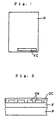
- Fig.1 shows a glossy photograph P as an image-receiving paper sheet in a state in which a voice code VC for reproducing a voice has been printed on a surface of the photograph P by a thermal transfer printer.
- the voice code VC is rectangular in entire shape and is formed of an assembly of fine dots.
- the voice is reproduced by placing the photograph P into a code reader and reading the voice code VC by the code reader.
- the voice code VC is printed in a lengthwise direction by the thermal transfer printer.
- the photograph has a glossing coating applied on its surface and for this reason, the direct spread of ink on the surface is poor. Therefore, to print the voice code VC on the surface of the photograph P, a foundation or undercoat F is first printed with a dear or white ink FI in that entire area on the surface of the photograph P in which voice code mass VM is to be formed, as shown in Fig.2. Then, the voice code mass VM is lap-printed on the undercoat F adapted for a good spread of ink with a predetermined color ink CI.
- an overcoat OC is lap-printed with a clear ink TI on the voice code mass VM and the entire exposed area of the surface of the undercoat F in order to improve the slidability of the voice code mass VM. In this manner, the printing of the voice code VC is completed.
- FIG.7 An embodiment of the thermal transfer printer for carrying out such printing is shown in Figa.7 to 9.
- a flat plate-like platen 2 is disposed on the thermal transfer printer 1 of the present embodiment at a desired location on a frame (not shown), so that its printing surface 2a is substantially vertical.
- a guide shaft 3 is disposed in parallel to the platen 2 in front of and below the platen 2.
- a carriage 4 divided vertically into two carriage sections is movably earned on the guide shaft 3.
- One 4a of the carriage sections shown on a lower side is referred to as a lower carriage section 4a carried on the guide shaft 3
- the other carriage section 4b shown on an upper side is referred to as an upper carriage section 4b to which a ribbon cassette 5 having an ink ribbon (which will be described hereinafter) accommodated therein is mounted, and which is movable vertically toward and away from the lower carriage section 4a.
- the carriage 4 is adapted to be reciprocally driven along the guide shaft 3 by driving a suitable driving belt 6 reeved around a pair of pulleys (not shown) by a drive means (not shown) such as a stepping motor.
- a thermal head 7 is disposed on the carriage 4 and adapted to be moved toward and away from a well-known head moving mechanism (not shown) which is opposed to the platen 2 and can be operated relative to the platen 2 by a driving force of a drive motor (not shown).
- the thermal head 7 is adapted to carry out the printing on the image receiving paper sheet transferred onto the platen 2 in a state of pressure contact with the platen 2 (i.e., in a head-down state).
- the thermal head 7 includes a plurality of heated elements (not shown) arranged in a row and selectively heated based on a desired printing information inputted by an input device (not shown) such as a keyboard.
- the thermal head 7 is designed, so that the energizing energy is selectively controlled at 15 stages, i.e., the time of energization of each heated element is controlled at 15 stages by a control section 25 which will be described hereinafter.
- the carriage 4 will be described in further detail.
- the carriage 4 is constructed such that the plate-like upper carriage section 4b substantially parallel to an upper surface of the lower carriage section 4a is mounted, so that it is moved in parallel toward and away from the lower carriage section 4a by a parallel crank mechanism 8.
- the parallel crank mechanism 8 is provided at each of laterally opposite ends of the carriage 4, as shown in Fig.9, and includes a pair of rinks 9a and 9b crossing each other in an X-ahape.
- the rinks 9a and 9b are pivoted at a location of crossing of them by a pin 10a, and slidably locked at their ends in elongated bores (not shown) defined left and right sides of the lower carriage section 4a and the upper carriage section 4b by pins 10b, 10c, 10d and 10e, respectively.
- a rotary crank mechanism 11 is disposed on the lower carriage 4a, so that the upper carriage 4b is operated in parallel movement by the rotary crank mechanism 11.
- the rotary crank mechanism 11 is comprised of a rotating plate 12 constituting a rotating member rotatably supported on the lower carriage section 4a, and a connecting rink 14 constituting a connecting member which is pivoted in an eccentric position on the rotating plate 12 by a pin 13a and pivoted at its tip end on the upper carriage 4b by a pin 13b.
- a suitable drive means such as a motor.
- plate-like arms 15 are provided in a risen manner at a distance approximately equal to the width of the ribbon cassette 5, and each have a tip end serving as an engage portions 15a which is curved gently inwards and which has projections formed at upper and lower ends thereof.
- a pair of rotatable bobbins 16 are disposed at a distance spaced apart from each other at widthwise central portions of the upper carriage section 4b to protrude upwards, so that the ink ribbon 17 can be traveled in a predetermined direction by the bobbins 16.
- One of the bobbins 16 is a delivery bobbin 16a for delivering the ink ribbon 17, and the other bobbin 16 is a take-up bobbin 16b for taking-up the ink ribbon 17.
- a photo-sensor 18a is disposed on an end edge of the carriage 4 farther from the plate 2 and serves as a sensor 18 for detecting the type of the ink ribbon 17 accommodated in the ribbon cassette 5.
- the photo-sensor 18 used in this embodiment is of a reflection type.
- the photo-sensor 18a is connected to the control section 25 for controlling the printing operation of the thermal transfer printer 1 disposed in the desired position.
- a substantially plate-like canopy 19 is disposed above the carriage 4 and supported on a frame (not shown) so that it can be opened and closed in directions indicated by arrows A in Fig.8.
- the canopy 19 functions as a paper sheet retainer at an outlet of a paper-sheet feed mechanism (not shown), and is disposed in an opposed relation to the carriage 4 and has a length substantially identical to a region of movement of the carriage 4.
- a plurality of cassette holders (not shown) for holding the ribbon cassette 5 are mounted at predetermined locations on that lower surface of the canopy 19 which confronts the carriage 4 in parallel.
- the three ribbon cassettes 5 having three types of ink ribbons 17a, 17b and 17c individually accommodated therein are arranged in a row in a direction of movement of the carriage 4 by the cassette holder.
- the ink ribbon 17a is used to print the undercoat F as a lowermost layer less influencing the printing accuracy with a clear or white ink in that entire area on the surface of the photograph P described with reference to Fig.2, in which voice code mass VM is to be formed.
- This ink ribbon 17a includes a substrate 30 formed of a PET film having a thickness of, for example, 4.5 ⁇ m, as shown in Fig.3.
- a back layer 31 formed of a fluorine-based resin is laminated with a thickness of, for example, 0.3 ⁇ m on aback of the substrate 30 to come into direct contact with the thermal head 7 for preventing the adhesion of the thermal head 7 to the substrate 30 due to the heat of the thermal head 7 and improving the slidability between the thermal head 7 and the ink ribbon 17a.
- a peel layer 32 formed of a resinous material is laminated with a thickness of, for example, 0.2 ⁇ m on a surface of the substrate 30 opposite from the back layer 31.
- An image-receiving layer 33 formed of a thermoplastic elastomer is laminated with a proper thickness on a surface of the peel layer 32 opposite from the substrate 30 for facilitating the spread of the voice code mass VM to be printed with the color ink CI.
- a titania-containing white ink layer 34 having an effect of hiding a picture image of the photograph is laminated with a proper thickness on a surface of the image-receiving layer 33 opposite from the peel layer 32.
- the ink ribbon 17b is used to lap-print the voice code mass VM on the undercoat F.
- the ink ribbon 17b includes a substrate 40 formed of a PET film having a thickness of, for example, 2.5 ⁇ m, as shown in Fig.4.
- Aback layer 41 formed of a silicone-based material and having a function similar to that of the back layer 31 is laminated with a thickness of, for example, 0.25 ⁇ m on a back of the substrate 40.
- a peel layer 42 formed of a wax material is laminated with a thickness of, for example, 1.0 ⁇ m on a surface of the substrate 40 opposite from the back layer 41.
- An intermediate layer 43 formed of a rosin-based tackifier for improving the spread of an over-coat OC (which will be described hereinafter) is laminated with a thickness of, for example, 0.3 ⁇ m on a surface of the peel layer 42 opposite from the substrate 40.
- a coloring ink layer 44 formed of a resinous material for contributing to the formation of the voice code mass VM is laminated with a thickness of, for example, 1.2 ⁇ m on a surface of the intermediate layer 43 from the peel layer 42.
- the ink ribbon 17c is used to lap-print the overcoat. OV less influencing the printing accuracy on the exposed areas of the undercoat F and on the voice code mass VM.
- the ink ribbon 17c includes a substrate 50 formed of a PET film having a thickness of, for example, 4.5 ⁇ m, as shown in Fig.5.
- a back layer 51 formed of a fluorine-based resin and having a function similar to that of each of the back layers 31 and 41 is laminated with a proper thickness on a back of the substrate 50.
- a clear ink layer 52 formed of a resinous material is laminated with a proper thickness on a surface of the substrate 50 opposite from the back layer 51.
- An adhesive layer 52 formed of a material similar to that of the adhesive layer 35 for improving the adhesion to the undercoat F and the voice code mass VM is laminated on a surface of the clear ink layer 52 opposite from the substrate 50.
- the length of the ink ribbon 17c used to print the overcoat OC forming the uppermost layer is shorter than the length of the ink ribbons 17a and 17b used for the other printing, as shown in Fig.6.
- a difference between the length of the ink ribbon 17c and the length of the ink ribbons 17a and 17b is a lengthwise length of the voice code VC which is at least one area to be printed.
- the difference between the length of the ink ribbon 17c and the length of the ink ribbons 17a and 17b is equal to or larger than a lengthwise length of one of the longest voice code masses.
- the length of the ink ribbon 17a used to print the undercoat F forming the lowermost layer less influencing the printing accuracy may be shorter than the length of the ink ribbons 17b and 17c used for the other printing.
- a stripe-like terminal end mark 60 is formed at a terminal end of each ink ribbon 17 and used to detect the end of each ink ribbon 17.
- a photo-sensor 27 is disposed sideways of the thermal head 7 of the lower carriage section 4a of the carriage 4 and serves as a detecting means opposed to an opening (not shown) of the ribbon cassette 5 mounted on the upper carriage section 4b for detecting the terminal end mark 60 of the ink ribbon 17.
- the photo-sensor 27 is connected to the control section 25 for the thermal transfer printer, so that when the photo-sensor 27 has detected the terminal end mark 60 of the ink ribbon 17 accommodated in the ribbon cassette 5, a detection signal is outputted to the control section 25.
- the control section 25 is provided with a informing section 26 for informing a user of the ribbon end by display or by voice upon inputting of the detection signal from the photo-sensor 27.
- the lengths of the ink ribbons 17a, 17b and 17c accommodated in the ribbon cassettes 5, respectively, are set such that the ink ribbon 17c used to print the uppermost layer is shorter than the other ink ribbons 17a and 17b, as described above.
- the undercoat F, the voice code mass VM and the overcoat OC are used through equal length thereof in order to print the voice code VC. Therefore, the terminal end mark 60 of the shorter ink ribbon 17c is first detected by the photo-sensor 27.
- the control section 25 ensures that the informing section 26 associated with informs the user of the fact that not only the end of the ink ribbon 17c but also the ends of the other two ink ribbons 17a and 17b actually not detected have been detected.
- Each of the ribbon cassettes 5 is selectively delivered between the canopy 9 and the upper carriage section 4b by movement of the parallel crank mechanism 8 operated in operative association with the rotary crank mechanism 11, as shown by arrows B in Fig.8.
- the ribbon cassettes 5 in the present embodiment are all formed into the same shape and the same size, irrespective of the type of the ink ribbon 17. Disposed in a pair of upper and lower case bodies 20 substantially rectangular in plane are a pair of reels supported rotatably, a pair of ribbon delivery rollers supported rotatably, and a plurality of guide rollers supported rotatably to face a ribbon path, which axe not shown.
- the ink ribbon 17 is reeved between the pair of reels, with an intermediate portion of the ink ribbon 17 being drawn to the outside.
- the pair of reels are operated, so that when the ribbon cassette 5 has been loaded onto the upper carriage section 4b, one of the reels acts as a take-up reel for taking-up a portion of the ink ribbon 17 placed into the printing, and the other reel acts as a delivery reel for delivering the ink ribbon.
- Each of the reels has a plurality of key grooves defined into a spline-like configuration in its inner peripheral surface at distances circumferentially spaced apart from one another.
- a take-up bore 21b is defined in the inner peripheral surface of the take-up reel, so that the take-up bobbin is engaged into the take-up bore 21b, and a delivery bore 21a is defined in the inner peripheral surface of the delivery reel, so that the delivery bobbin is engaged into the delivery bore 21a.
- a recess 22 fading outwards with respect to the thermal head 7 is defined in that face of the ribbon cassette 5 which is opposed to the platen 2 in a state in which the ribbon cassette 5 has been loaded on the carriage 4.
- the intermediate portion of the ink ribbon 17 is drawn out within the recess 22.
- a discriminating mark 23 for determining the type of the ink ribbon 17 accommodated within each cassette 5 is applied to that rear face of the ribbon cassette 5 which extends in parallel to the face of the ribbon cassette 5 having the recess 22 defined therein.
- the discriminating mark 23 is formed by a reflection seal 24 having a number of stripe-shaped non-reflective portions 24a, which is varied depending on the type of the ink ribbon 17.
- the type of the ink ribbon 17a, 17b, 17c accommodated in the ribbon cassette 5 is determined by detecting the discriminating mark 23 by the photo-sensor 18a mounted on the carriage 4, outputting a detection signal to the control section 25 for the thermal transfer printer 1, and counting the number of the discriminating marks 23 in each ribbon cassette 5 in the control section 25.
- a reflection seal 24A having three non-reflective portions 24a are disposed as discriminating marks in the ribbon cassette 5a shown on the leftmost side in Fig.7.
- the left end of the rear face, shown this side in Fig.7, of the ribbon cassette 5 is defined as a reference position BP for detecting the discriminating mark 23.
- the distance L from the reference position to a right end face of the non-reflective portion 24a located at the right end in Fig.7 of the discriminating mark 23 is set at the same value in all of the discriminating marks 23, and the desired non-reflective portions 24a for discriminating the type of the ink ribbon 17a are formed within the distance L.
- the carriage 4 can be stopped in a state in which the discriminating mark 23 placed into use has been detected by the photo-sensor 18a, and when the carriage 4 is in its stopped state, the ribbon cassette 5 accommodated in the cassette holder is delivered onto the upper carriage section 4b.
- the control section 25 is designed to carry out the control such that, after the informing section 26 informs the user of the fact that when the end of the shorter ink ribbon 17c has been detected, the ends of the two other ink ribbons 17a and 17b actually not detected has been also detected, the ribbon cassettes 5a and 5b having the two other ink ribbons 17a and 17b accommodated therein are sequentially loaded onto the carriages 4, and the ink ribbons 17a and 17 are delivered, until the ribbon ends have been revealed. This is to ensure that even when each ink ribbon 17 is a so-called multi-ribbon, the drawn-out of head can be achieved automatically.
- control section 25 is designed to ensure that when the terminal end marks 60 of the ink ribbons 17a and 17b cannot be detected even if the ink ribbons 17a and 17b has been delivered in a predetermined amount until they has reached the ribbon ends, the informing section 26 informs the user of the fact that there is a problem arisen in the situations of the ink ribbons 17a and 17b. This is because it can be recognized that there is a problem such as a breaking or a winding failure arisen in the ink ribbons 17a and 17b which has not reached their ribbon ends.
- the ribbon cassettes 5a, 5b and 5c having the three types of ink ribbons 17a, 17b and 17c are accommodated respectively therein are new ones by which the old ribbon cassettes have been replaced simultaneously.
- the carriage 4 located in a home position is moved by a command from the control section 25, and the photo-sensor 18a disposed on the carriage 4 detects the discriminating mark 23 on the ribbon cassette 5.
- the photo-sensor 18a delivers a detection signal peculiar to the discriminating mark 23 formed by the arrangement and pitches of the non-reflective portions 24a to the control section 25.
- the control section 25 It is determined in the control section 25 whether the detection signal represents the discriminating mark 23 corresponding to the command emitted in the control section 25.
- the detection signal represents the discriminating mark 23 corresponding to the command
- the movement of the carriage 4 is stopped.
- the foundation or undercoat F, the voice code mass VM and the overcoat OC are printed in the named order and hence, the ribbon cassette 5a having the ink ribbon 17a accommodated therein for the undercoat F is first discriminated.
- the ribbon cassette 5 with the selected ink ribbon 17a accommodated therein for the undercoat is selectively delivered from the canopy 19 to the upper carriage section 4b, as shown by the arrows B in Fig.8, by the parallel crank mechanism 8 and the rotary crank mechanism 11, and the ribbon cassette 5a is set onto the carriage 4, thus completing the operation of selecting the ribbon cassette 5a.
- the photograph P on which the voice code is to be printed is set between the platen 2 and the thermal head 7 by an operator or by a feed device (not shown), whereby the printing of the undercoat F is started.
- the thermal head 7 is moved downwards by the command from the control section 25 to come into pressure contact with the platen 2 with the ink ribbon 17a and the photograph P interposed therebetween, and the carriage 4 is moved.
- thermoplastic elastomer of the image-receiving layer 33 and the while ink of the white ink layer 34 on the ink ribbon 17a are peeled off from the peel layer 32 and transferred onto the photograph P.
- the ribbon cassette 5a used in the printing of the undercoat F is delivered from the upper carriage section 4b to the canopy 19 by an operation reverse from that described above. Then, the ribbon cassette 5b with the ink ribbon 17b accommodated therein for use in the printing of the voice code mass VM is discriminated and delivered from the canopy 19 to the upper carriage section 4b, whereby the printing of the voice code mass VM is started.
- the thermal head 7 is moved downwards into pressure contact with the platen 2 with the ink ribbon 17b and the photograph P interposed therebetween by the command from the control section 25, and the carriage 4 is moved.
- the heated elements of the thermal head 7 corresponding to the voice code mass VM are heated, while moving the thermal head 7 relative to the photograph P in the above manner, the rosin-based tackifier of the intermediate layer 43 and the ink of the coloring ink layer 44 on the ink ribbon 17b are peeled off from the peel layer 42 and transferred onto the photograph P, thus completing the printing of the voice code mass VM which is the assembly of dots corresponding to voice.
- the ribbon cassette 5b used in the printing of the voice code mass VM is delivered from the upper carriage section 4b to the canopy 19 by an operation reverse from that described above. Then, the ribbon cassette 5c with the ink ribbon 17c accommodated therein for use in the printing of the overcoat OC is discriminated and delivered from the canopy 19 to the upper carriage section 4b, whereby the printing of the overcoat OC is started.
- the thermal head 7 is moved downwards into pressure contact with the platen 2 with the ink ribbon 17b and the photograph P interposed therebetween by the command from the control section 25, and the carriage 4 is moved.
- the heated elements of the thermal head 7 corresponding to the voice code mass VM and the exposed entire area of the undercoat F are heated, while moving the thermal head 7 relative to the photograph P in the above manner, the clear ink of the clear ink layer 52 and the adhesive essentially comprising the thermoplastic elastomer of the adhesive layer 53 are peeled off from the substrate 50 and transferred onto the photograph P, thus completing the printing of the overcoat OC for improving the slidability of the voice code mass VM.
- the operation is shifted to the printing of the subsequent voice code.
- the ribbon cassette 5c for the overcoat OC loaded on the carriage 4 is replaced by the ribbon cassette 5a for the printing of the undercoat F, whereby the printing of the undercoat F is carried out again, followed by the printings of the voice code mass VM and the overcoat OC.
- the lengths of the ink ribbons 17 accommodated in the ribbon cassettes 5 are set such that the ink ribbon 17c for the overcoat OC which is the uppermost layer is shorter than the other ink ribbons 17a and 17b at least by the length of the voice code VC. Therefore, the photo-sensor 27 first detects the terminal end mark 60 of the ink ribbon 17c for the overcoat OC.
- control section 25 ensures that it is determined that not only the end of the ink ribbon 17c actually detected but also the ends of the two other ink ribbons 17a and 17b actually not detected have been detected, and the informing section 26 informs the user of this fact. Then, the control section 25 carries out such control that the ink ribbons 5a and 5b with the two other ink ribbons 17a and 17b accommodated therein are sequentially loaded onto the carriage 4, and the ink ribbons 17a and 17b are delivered until their ends are revealed.
- the operator replaces all the ribbon cassettes 5 simultaneously by new ones. This is because in the printing of the voice code mass VM, if the replacement of the ink ribbons 17a and 17b is carried out during of printing of one voice code VC, gaps ox joints such as overlapped portions are produced in the printing using new ink ribbons 17a and 17b replacing the old ink ribbons 17a and 17b, thereby bringing about a disadvantage in the formed voice code VC, whereas in the uppermost overcoat OC, no particular adverse influence is produced even if gaps or overlapped portions are produced in the printing.
- the printing of the overcoat OC with the ink ribbon 17c in one voice code VC may be carried out twice by replacing the ribbon cassettes 5c by new one. This is free of any problem, because even if gaps or joints such as overlapped portions are produced in the overcoat OC, they exert no adverse influence.
- the voice code mass VM is formed by one run of the printing and hence, it is possible to form the voice code having a good reproducibility.
- terminal end marks have been formed on all the ink ribbons in the embodiment, but a terminal end mark may be formed in only the ink ribbon for use in the printing of the uppermost layer.
- the ink ribbon less influencing the printing accuracy e.g., the ink ribbon for use on the printing of the lowermost layer may be shorter in length than the other ink ribbons.
- the two or more ink ribbons such as the ink ribbon for use in the printing of the uppermost layer and the ink ribbon for use in the printing of the lowermost layer may be shorter in length than the other ink ribbon. In this case, the length of the ink ribbon to be discarded may be further shorter.
Landscapes
- Impression-Transfer Materials And Handling Thereof (AREA)
Claims (10)
- Eine Farbbandanordnung zur Verwendung in einem Thermotransferdrucker, die eine Vielzahl von Farbbändern beinhaltet, so dass Drucken in Schichten unter Verwendung der Farbbänder in vorbestimmter Reihenfolge ausgeführt werden kann, wobei mindestens ein die Druckgenauigkeit weniger beeinflussendes Farbband kürzer als die anderen Farbbänder ist, wobei das kürzere Farbband eine an seinem Terminalende gebildete Terminalendmarkierung aufweist.
- Farbbandanordnung gemäß Anspruch 1, wobei das kürzere Farbband ein Farbband zur Verwendung beim Drucken einer obersten Schicht ist.
- Farbbandanordnung gemäß Anspruch 2, wobei das Farbband zur Verwendung beim Drucken einer obersten Schicht ein Farbband für eine eine klare Farbe aufweisende Oberschicht ist.
- Farbbandanordnung gemäß Anspruch 1, wobei das kürzere Farbband ein Farbband zur Verwendung beim Drucken einer untersten Schicht ist.
- Farbbandanordnung gemäß einem der Ansprüche 1 bis 4, wobei das kürzere Farbband um eine zum Drucken mindestens einer Druckfläche erforderliche Länge kürzer ist als die anderen Farbbänder.
- Ein Thermotransferdrucker, der eine Vielzahl von Farbbändern beinhaltet und entworfen ist, um eine Grundierung oder Unterschicht mit einem Farbband, das eine klare Farbe oder eine weiße Farbe aufweist, zu drucken, dann ein Bild auf der Unterschicht mit einem Farbband, das eine Farbe einer vorbestimmten Farbe aufweist, zu drucken und ferner eine Oberschicht auf der bildgeformten Fläche mit einem Farbband, das eine klare Farbe aufweist, in Schicht zu drucken, wobei mindestens ein die Druckgenauigkeit weniger beeinflussendes Farbband kürzer als die anderen Farbbänder ist, wobei der Thermotransferdrucker eine an einem Terminalende des kürzeren Farbbands gebildete Terminalendmarkierung, einen Erkennungsabschnitt zum Erkennen der Terminalendmarkierung des kürzeren Farbbands und einen Kontrollabschnitt, der angepasst ist, um ein Bandende durch die Terminalendmarkierung des durch den Erkennungsabschnitt erkannten Farbbands zu prüfen und einen Benutzer über das Bandende zu informieren, aufweist.
- Thermotransferdrucker gemäß Anspruch 6, wobei das kürzere Farbband um eine für das Drucken mindestens einer Druckfläche erforderlichen Länge kürzer ist als die anderen Farbbänder.
- Thermotransferdrucker gemäß Anspruch 6 oder 7, wobei der Kontrollabschnitt, wenn der Erkennungsabschnitt die Terminalendmarkierung des kürzeren Farbbands erkennt, einen Benutzer darüber informiert, dass alle Farbbänder ausgelegt worden sind, als ob diese ihre Bandenden erreicht haben.
- Thermotransferdrucker gemäß Anspruch 6 oder 7, wobei der Kontrollabschnitt, wenn der Erkennungsabschnitt die Terminalendmarkierung des kürzeren Farbbands erkennt, einen Benutzer darüber informiert, dass alle Farbbänder ausgelegt worden sind, als ob diese ihre Bandenden erreicht haben, und alle verbleibenden Teile der Farbbänder ausgelegt werden, bis diese ihre Enden erreichen.
- Thermotransferdrucker gemäß Anspruch 9, wobei der Kontrollabschnitt, wenn ein bestimmtes, sein Bandende noch nicht erreichendes Farbband zu dem Zeitpunkt existiert, wenn alle verbleibenden Teile der Farbbänder in einer vorbestimmten Menge ausgelegt worden sind, den Benutzer darüber informiert, dass sich in der Situation des bestimmten Farbbands ein Problem ergeben hat.
Applications Claiming Priority (4)
| Application Number | Priority Date | Filing Date | Title |
|---|---|---|---|
| JP16862698 | 1998-06-16 | ||
| JP16862698 | 1998-06-16 | ||
| JP11106723A JP2000071589A (ja) | 1998-06-16 | 1999-04-14 | インクリボン集合体およびこのインクリボン集合体を使用する熱転写プリンタ |
| JP10672399 | 1999-04-14 |
Publications (2)
| Publication Number | Publication Date |
|---|---|
| EP0965458A1 EP0965458A1 (de) | 1999-12-22 |
| EP0965458B1 true EP0965458B1 (de) | 2003-08-13 |
Family
ID=26446832
Family Applications (1)
| Application Number | Title | Priority Date | Filing Date |
|---|---|---|---|
| EP99304492A Expired - Lifetime EP0965458B1 (de) | 1998-06-16 | 1999-06-09 | Farbbandanordnung und seine Verwendung in einem Wärmübertragungsdrucker |
Country Status (6)
| Country | Link |
|---|---|
| US (1) | US6211895B1 (de) |
| EP (1) | EP0965458B1 (de) |
| JP (1) | JP2000071589A (de) |
| CN (1) | CN1120779C (de) |
| CA (1) | CA2275084A1 (de) |
| DE (1) | DE69910306T2 (de) |
Families Citing this family (8)
| Publication number | Priority date | Publication date | Assignee | Title |
|---|---|---|---|---|
| JP4319740B2 (ja) * | 1999-06-24 | 2009-08-26 | アルプス電気株式会社 | 印刷物および印刷方法ならびに印刷装置 |
| DE10023319B4 (de) * | 2000-05-12 | 2008-07-10 | Man Roland Druckmaschinen Ag | Verfahren zum Umspulen von Thermotransferband zum Bebildern von Druckformen |
| JP2008246793A (ja) | 2007-03-29 | 2008-10-16 | Fujifilm Corp | 活性エネルギー線硬化型インクジェット記録装置 |
| JP5853763B2 (ja) * | 2012-02-28 | 2016-02-09 | セイコーエプソン株式会社 | 捺染方法 |
| CN103625122B (zh) * | 2012-08-27 | 2016-03-23 | 山东新北洋信息技术股份有限公司 | 热转印打印装置及其控制方法和装置 |
| US9399356B1 (en) * | 2015-09-21 | 2016-07-26 | Toshiba Tec Kabushiki Kaisha | Printer apparatus |
| JP7047266B2 (ja) * | 2017-06-26 | 2022-04-05 | カシオ計算機株式会社 | 印刷装置、印刷装置の印刷制御方法、及び、プログラム |
| JP6926764B2 (ja) * | 2017-07-19 | 2021-08-25 | 富士フイルムビジネスイノベーション株式会社 | 印刷制御装置、印刷装置、表示装置および印刷システム |
Family Cites Families (7)
| Publication number | Priority date | Publication date | Assignee | Title |
|---|---|---|---|---|
| JPS62173279A (ja) * | 1986-01-27 | 1987-07-30 | Nec Corp | 抵抗リボン式印字装置 |
| JPH0347782A (ja) * | 1989-07-14 | 1991-02-28 | Nec Corp | 印字用リボン |
| US5720562A (en) * | 1994-09-01 | 1998-02-24 | Sharp Kabushiki Kaisha | Printer system with automatic ink ribbon cassette exchange function |
| JPH08300782A (ja) * | 1995-04-28 | 1996-11-19 | Alps Electric Co Ltd | カラーインクリボン |
| JPH09202026A (ja) * | 1996-01-25 | 1997-08-05 | Casio Comput Co Ltd | 印刷装置 |
| JP3318486B2 (ja) * | 1996-06-14 | 2002-08-26 | アルプス電気株式会社 | 熱転写プリンタ |
| JPH1148591A (ja) * | 1997-07-31 | 1999-02-23 | Nisca Corp | 画像形成装置 |
-
1999
- 1999-04-14 JP JP11106723A patent/JP2000071589A/ja active Pending
- 1999-06-09 DE DE69910306T patent/DE69910306T2/de not_active Expired - Fee Related
- 1999-06-09 EP EP99304492A patent/EP0965458B1/de not_active Expired - Lifetime
- 1999-06-15 CA CA002275084A patent/CA2275084A1/en not_active Abandoned
- 1999-06-16 CN CN99108893.XA patent/CN1120779C/zh not_active Expired - Fee Related
- 1999-06-16 US US09/334,717 patent/US6211895B1/en not_active Expired - Fee Related
Also Published As
| Publication number | Publication date |
|---|---|
| JP2000071589A (ja) | 2000-03-07 |
| CN1239039A (zh) | 1999-12-22 |
| DE69910306T2 (de) | 2004-06-24 |
| DE69910306D1 (de) | 2003-09-18 |
| EP0965458A1 (de) | 1999-12-22 |
| CA2275084A1 (en) | 1999-12-16 |
| CN1120779C (zh) | 2003-09-10 |
| US6211895B1 (en) | 2001-04-03 |
Similar Documents
| Publication | Publication Date | Title |
|---|---|---|
| US7277109B2 (en) | Thermal transfer printer | |
| US5064301A (en) | Thermal printer | |
| US5021804A (en) | Thermal transfer color printer | |
| JPS6330277A (ja) | 熱転写リボン機構及び記録方法 | |
| US6211895B1 (en) | Ink ribbon assembly, and thermal transfer printer using the same | |
| US7381001B2 (en) | Thermal transfer printer | |
| US6250824B1 (en) | Thermal transfer recording method and thermal transfer printer | |
| JP2924837B2 (ja) | ラベルプリンタ | |
| JP2002337373A (ja) | 熱転写ラインプリンタ | |
| US5735616A (en) | Printing mechanism with means for preventing contact between ink ribbon and drive IC of thermal head | |
| JP2005335306A (ja) | 通帳類の印刷装置及び印刷方法 | |
| JP3593258B2 (ja) | 熱転写記録方法 | |
| KR20000067745A (ko) | 잉크 리본 집합체 및 이 잉크 리본 집합체를 사용하는 열전사프린터 | |
| JP4515743B2 (ja) | 通帳類印刷装置及び通帳類印刷方法 | |
| US5896161A (en) | Method of printing a high-quality image, using a thermal transfer printer | |
| JP3483404B2 (ja) | サーマルプリンタ | |
| JPH1120322A (ja) | 下地・仕上処理用インクリボン、この下地・仕上処理用インクリボンを収納したリボンカセット、熱転写プリンタおよびこの熱転写プリンタの記録方法 | |
| JPH11221935A (ja) | インクカートリッジおよび熱転写プリンタ装置 | |
| JP2000000983A (ja) | 熱転写プリンタ | |
| JPS6212030B2 (de) | ||
| JPH10202928A (ja) | 記録方法および記録装置 | |
| JPH0872372A (ja) | 印字装置及びそのインクリボン | |
| JP2006256245A (ja) | 通帳類印刷装置 | |
| JPH1148591A (ja) | 画像形成装置 | |
| JP2000343802A (ja) | 記録方法および記録装置 |
Legal Events
| Date | Code | Title | Description |
|---|---|---|---|
| PUAI | Public reference made under article 153(3) epc to a published international application that has entered the european phase |
Free format text: ORIGINAL CODE: 0009012 |
|
| AK | Designated contracting states |
Kind code of ref document: A1 Designated state(s): CH DE FR GB IT LI |
|
| AX | Request for extension of the european patent |
Free format text: AL;LT;LV;MK;RO;SI |
|
| 17P | Request for examination filed |
Effective date: 20000125 |
|
| AKX | Designation fees paid |
Free format text: CH DE FR GB IT LI |
|
| GRAH | Despatch of communication of intention to grant a patent |
Free format text: ORIGINAL CODE: EPIDOS IGRA |
|
| GRAH | Despatch of communication of intention to grant a patent |
Free format text: ORIGINAL CODE: EPIDOS IGRA |
|
| GRAA | (expected) grant |
Free format text: ORIGINAL CODE: 0009210 |
|
| RAP1 | Party data changed (applicant data changed or rights of an application transferred) |
Owner name: OLYMPUS OPTICAL CO., LTD. Owner name: NORITSU KOKI CO., LTD. Owner name: ALPS ELECTRIC CO., LTD. |
|
| AK | Designated contracting states |
Designated state(s): CH DE FR GB IT LI |
|
| PG25 | Lapsed in a contracting state [announced via postgrant information from national office to epo] |
Ref country code: LI Free format text: LAPSE BECAUSE OF FAILURE TO SUBMIT A TRANSLATION OF THE DESCRIPTION OR TO PAY THE FEE WITHIN THE PRESCRIBED TIME-LIMIT Effective date: 20030813 Ref country code: IT Free format text: LAPSE BECAUSE OF FAILURE TO SUBMIT A TRANSLATION OF THE DESCRIPTION OR TO PAY THE FEE WITHIN THE PRE;WARNING: LAPSES OF ITALIAN PATENTS WITH EFFECTIVE DATE BEFORE 2007 MAY HAVE OCCURRED AT ANY TIME BEFORE 2007. THE CORRECT EFFECTIVE DATE MAY BE DIFFERENT FROM THE ONE RECORDED.SCRIBED TIME-LIMIT Effective date: 20030813 Ref country code: CH Free format text: LAPSE BECAUSE OF FAILURE TO SUBMIT A TRANSLATION OF THE DESCRIPTION OR TO PAY THE FEE WITHIN THE PRESCRIBED TIME-LIMIT Effective date: 20030813 |
|
| REG | Reference to a national code |
Ref country code: GB Ref legal event code: FG4D |
|
| REG | Reference to a national code |
Ref country code: CH Ref legal event code: EP |
|
| REF | Corresponds to: |
Ref document number: 69910306 Country of ref document: DE Date of ref document: 20030918 Kind code of ref document: P |
|
| REG | Reference to a national code |
Ref country code: CH Ref legal event code: PL |
|
| PGFP | Annual fee paid to national office [announced via postgrant information from national office to epo] |
Ref country code: FR Payment date: 20040608 Year of fee payment: 6 |
|
| PGFP | Annual fee paid to national office [announced via postgrant information from national office to epo] |
Ref country code: GB Payment date: 20040609 Year of fee payment: 6 |
|
| ET | Fr: translation filed | ||
| PGFP | Annual fee paid to national office [announced via postgrant information from national office to epo] |
Ref country code: DE Payment date: 20040617 Year of fee payment: 6 |
|
| PLBE | No opposition filed within time limit |
Free format text: ORIGINAL CODE: 0009261 |
|
| STAA | Information on the status of an ep patent application or granted ep patent |
Free format text: STATUS: NO OPPOSITION FILED WITHIN TIME LIMIT |
|
| 26N | No opposition filed |
Effective date: 20040514 |
|
| PG25 | Lapsed in a contracting state [announced via postgrant information from national office to epo] |
Ref country code: GB Free format text: LAPSE BECAUSE OF NON-PAYMENT OF DUE FEES Effective date: 20050609 |
|
| PG25 | Lapsed in a contracting state [announced via postgrant information from national office to epo] |
Ref country code: DE Free format text: LAPSE BECAUSE OF NON-PAYMENT OF DUE FEES Effective date: 20060103 |
|
| PG25 | Lapsed in a contracting state [announced via postgrant information from national office to epo] |
Ref country code: FR Free format text: LAPSE BECAUSE OF NON-PAYMENT OF DUE FEES Effective date: 20060228 |
|
| GBPC | Gb: european patent ceased through non-payment of renewal fee |
Effective date: 20050609 |
|
| REG | Reference to a national code |
Ref country code: FR Ref legal event code: ST Effective date: 20060228 |