EP0965464A2 - LKW-Reifen - Google Patents
LKW-Reifen Download PDFInfo
- Publication number
- EP0965464A2 EP0965464A2 EP99304817A EP99304817A EP0965464A2 EP 0965464 A2 EP0965464 A2 EP 0965464A2 EP 99304817 A EP99304817 A EP 99304817A EP 99304817 A EP99304817 A EP 99304817A EP 0965464 A2 EP0965464 A2 EP 0965464A2
- Authority
- EP
- European Patent Office
- Prior art keywords
- axial grooves
- blocks
- grooves
- central
- groove
- Prior art date
- Legal status (The legal status is an assumption and is not a legal conclusion. Google has not performed a legal analysis and makes no representation as to the accuracy of the status listed.)
- Granted
Links
- 239000011324 bead Substances 0.000 description 5
- 229910000831 Steel Inorganic materials 0.000 description 3
- 239000010959 steel Substances 0.000 description 3
- 239000010426 asphalt Substances 0.000 description 2
- 230000000694 effects Effects 0.000 description 2
- 239000000835 fiber Substances 0.000 description 2
- 239000004677 Nylon Substances 0.000 description 1
- 229920000297 Rayon Polymers 0.000 description 1
- 230000001154 acute effect Effects 0.000 description 1
- 239000004760 aramid Substances 0.000 description 1
- 229920003235 aromatic polyamide Polymers 0.000 description 1
- 230000004323 axial length Effects 0.000 description 1
- 230000015572 biosynthetic process Effects 0.000 description 1
- 230000003247 decreasing effect Effects 0.000 description 1
- 229920001778 nylon Polymers 0.000 description 1
- 238000011056 performance test Methods 0.000 description 1
- 229920000728 polyester Polymers 0.000 description 1
- 239000002964 rayon Substances 0.000 description 1
- XLYOFNOQVPJJNP-UHFFFAOYSA-N water Substances O XLYOFNOQVPJJNP-UHFFFAOYSA-N 0.000 description 1
Images


Classifications
-
- B—PERFORMING OPERATIONS; TRANSPORTING
- B60—VEHICLES IN GENERAL
- B60C—VEHICLE TYRES; TYRE INFLATION; TYRE CHANGING; CONNECTING VALVES TO INFLATABLE ELASTIC BODIES IN GENERAL; DEVICES OR ARRANGEMENTS RELATED TO TYRES
- B60C11/00—Tyre tread bands; Tread patterns; Anti-skid inserts
- B60C11/03—Tread patterns
- B60C11/13—Tread patterns characterised by the groove cross-section, e.g. for buttressing or preventing stone-trapping
- B60C11/1369—Tie bars for linking block elements and bridging the groove
-
- B—PERFORMING OPERATIONS; TRANSPORTING
- B60—VEHICLES IN GENERAL
- B60C—VEHICLE TYRES; TYRE INFLATION; TYRE CHANGING; CONNECTING VALVES TO INFLATABLE ELASTIC BODIES IN GENERAL; DEVICES OR ARRANGEMENTS RELATED TO TYRES
- B60C11/00—Tyre tread bands; Tread patterns; Anti-skid inserts
- B60C11/03—Tread patterns
- B60C11/11—Tread patterns in which the raised area of the pattern consists only of isolated elements, e.g. blocks
-
- B—PERFORMING OPERATIONS; TRANSPORTING
- B60—VEHICLES IN GENERAL
- B60C—VEHICLE TYRES; TYRE INFLATION; TYRE CHANGING; CONNECTING VALVES TO INFLATABLE ELASTIC BODIES IN GENERAL; DEVICES OR ARRANGEMENTS RELATED TO TYRES
- B60C11/00—Tyre tread bands; Tread patterns; Anti-skid inserts
- B60C11/03—Tread patterns
- B60C11/12—Tread patterns characterised by the use of narrow slits or incisions, e.g. sipes
Definitions
- the present invention relates to a pneumatic tyre, more particularly to a heavy duty all-season tyre improved in uneven wear without sacrificing running performance.
- an object of the present invention to provide a heavy duty tyre in which uneven wear especially of the second block rows can be effectively prevented.
- a heavy duty tyre comprises at least four main grooves extending continuously in the tyre circumferential direction and axial grooves intersecting the main grooves so as to divide a tread portion into two rows of circumferentially arranged shoulder blocks, two rows of circumferentially arranged middle blocks and at least one row of circumferentially arranged central blocks, the axial grooves including central axial grooves dividing the central blocks, middle axial grooves dividing the middle blocks, and outer axial grooves dividing the shoulder blocks, wherein the central axial grooves are substantially straight grooves, the middle axial grooves are curved grooves, the outer axial grooves are substantially straight grooves or slightly bent grooves, the middle blocks each being provided with a longitudinal sipe extending along the axially outer edge of the block and a lateral sipe extending from the axially inner edge of the block to the longitudinal sipe.
- the middle axial grooves in each row are curved towards the same circumferential direction, but, between the two rows of the middle blocks, the curving directions are reversed.
- the lateral sipes in each row are curved in the same manner as the middle axial grooves therein so that the lateral sipes and middle axial grooves are substantially parallel with each other.
- the central axial grooves in each row are inclined in the same direction so that the central axial grooves are substantially parallel with each other.
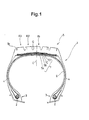
- heavy duty tyre 1 comprises a tread portion 5, a pair of sidewall portions 4, a pair of bead portions 3 each with a bead core 2 therein, a carcass 6 extending between the bead portions 3, and a belt 7 disposed radially outside the carcass 6 in the tread portion 5.
- the heavy duty tyre 1 is a so-called all-season radial tyre of size 11R22.5.
- the carcass 6 is composed of at least one ply of cords arranged at an angle of from 70 to 90 degrees with respect to the tyre equator C, extending between the bead portions 3 through the tread portion 5 and sidewall portions 4 and being turned up around the bead cores 2 from the inside to outside of the tyre.
- inorganic cord such as steel cords and organic fibre cords, e.g. polyester, nylon, rayon, aromatic polyamide fibre and the like can be used.
- the carcass 6 is composed of a single ply of steel cords arranged radially at substantially 90 degrees.
- the belt 7 is composed of at least two crossed plies of parallel cords.
- there are four plies of steel cords including a radially innermost first ply 7A made of cords laid at an angle of from 50 to 70 degrees and second to fourth plies 7B, 7C and 7D each made of cords laid at an angle of not more than 30 degrees with respect to the tyre equator C.
- the tread portion 5 is, as shown in Fig.2, provided with at least four longitudinal main grooves G and axial grooves Y intersecting the longitudinal main grooves G to form a block pattern.
- the negative ratio of the tread patter is decreased and set in a range of from 0.26 to 0.34.
- the negative ratio is a ratio S1/S of grooved area S1 occupied in the total ground contact area S.
- the longitudinal main grooves G extend continuously in the circumferential direction and have a groove width Wg of not less than 2.0 mm, but preferably not more than 19.0 mm.
- the longitudinal main grooves G include an axially inner groove G1 disposed on each side of the tyre equator C, and an axially outer groove G2 disposed on the axially outside thereof.
- the number of longitudinal main grooves G is four or five, preferably four.
- the longitudinal main grooves G are axially arranged substantially equi-distantly within the tread width.
- all of the four longitudinal main grooves G are a substantially straight groove having a groove width Wg of not less than 7.0 mm.
- the groove width Wg is substantially constant along the groove length.
- a zigzag groove may be used.
- the above-mentioned axial grooves Y include central axial grooves Y1 extending between the inner grooves G1, middle axial grooves Y2 extending between the inner grooves G1 and outer grooves G2, and outer axial grooves Y3 extending between the outer grooves G2 and tread edges Te. Therefore, a circumferential row R1 of central blocks B1 is formed between the adjacent inner grooves G1 and G1, and a circumferential row R2 of middle blocks B2 is formed between each of the inner grooves G1 and the adjacent outer groove G2, and a circumferential row R3 of shoulder blocks B3 is formed between each of the outer grooves G2 and the adjacent tread edge Te.
- the axial grooves Y are defined as having a groove width Wy of at least 2.0 mm.
- the axial grooves Y2 are formed as a curved groove 11, 50% or more of which is curved at a single radius R of from 0.5 to 1.0 times the axial length Ly. All the axial grooves Y2 in each row R2 are curved towards one circumferential direction F1, and the centre of curvature is located between the inner and outer grooves G1 and G2.
- the crown P of the axial groove in the direction F1 is located between the main grooves G1 and G2, and thus from the crown P towards each side thereof, the axial groove is inclined to the reverse direction F2.
- the crown P is preferably located in the central one third part 11M of the axial groove Y2 in the tyre axial direction.
- a multi-radius curve or a combination of curve and straight region may be used.
- the central axial grooves Y1 are substantially straight and inclined in the same direction at an angle of not more than 60 degrees (for example 40 degrees) with respect to the axial direction of the tyre.
- the outer axial grooves Y3 are a substantially straight groove or a slightly bent groove which is substantially parallel with the tyre axial direction.
- each of the middle blocks B2 is further provided with a longitudinal sipe 15 and an arcuate lateral sipe 16 in a T-shaped formation.
- the longitudinal sipe 15 extends circumferentially along the axially outer edge 120 of the middle block B2 across the circumferential length thereof.
- the axial width W1 of a part 17 defined between the longitudinal sipe 15 and the outer edge 120 is set in the range of about 2.0 to 8.0 mm.
- the arcuate lateral sipe 16 is substantially parallel with the axial grooves Y2 and extends from the axially inner edge 12i to the longitudinal sipe 15.
- the longitudinal sipes 15 prevent uneven wear from extending axially inwardly from the axially outer edge 120 of the block B2.
- one lateral sipe 16 is disposed in the centre of block B2 in the circumferential direction, and all the longitudinal sipes 15 in each row R2 are straight and arranged in line.
- each of the central blocks B1 is provided with a straight sipe 13 substantially parallel with the straight axial grooves Y1.
- the sipes 13, 15 and 16 improve wet performance and on-the-snow performance.
- the sipes are defined as having a width of less than about 1.5 mm.
- each of the shoulder blocks B3 is provided along and adjacently to the tread edge Te with a narrow shoulder groove 19 having a groove width of less than 3.0 mm.
- the depth of the axial grooves Y is set in the range of from 0.7 to 1.0 times the depth DG of the longitudinal main grooves G.
- the central axial grooves Y1 and middle axial grooves Y2 have a constant depth of 1.0 times the main groove depth DG.
- the outer axial grooves Y3 have a variable depth, and a shallow part is formed in an axial centre thereof which is about one third of the groove length. The depth is about 0.7 times DG in the shallow part, but on both sides thereof 1.0 times DG. Further, the shallow part is provided with a sipe along the groove centre line, and the sipe depth is about 0.5 times DG.
- the depth of the sipes 13, 15 and 16 is set in the range of from 0.5 to 1.0 times the main groove depth DG.
- the sipes 13 in the central blocks B1 have a maximum depth of 1.0 times DG, and one or two shallow parts being less than 0.5 times DG are formed.
- the sipes 16 on the middle blocks B2 have a maximum depth of 1.0 times DG, and one or two shallow parts being less than 0.5 times DG are formed.
- the sipes 15 have a substantially constant depth of about 0.7 or 0.8 times DG.
- the depth of the narrow shoulder grooves 19 is set in the range of from 0.6 to 0.9 times the main groove depth DG.
- the axial grooves Y and sipes 13 in each row R1 are inclined in the same direction so that they are parallel with each other.
- the inclination angle thereof is in the range of from about 40 to 60 degrees with respect to the tyre equator C.
- the axial grooves Y2 and sipes 16 in each row R2 are curved or inclined in the same manner so that they are substantially parallel to each other.
- the inclining direction at the axially inner ends of the axial grooves Y2 and sipes 16 is the same as that of the axial grooves Y1 and sipes 13 in the adjacent central block row R1.
- the inclination angle at the axially inner end is in the range of about 50 to 70 degrees with respect to the tyre equator C, which is substantially same as the inclination angle at the longitudinal sipe 15.
- the curved direction on one side of the tyre equator C is reversed to that on the other side, and the left axial grooves Y2, central axial groove Y1 and right axial groove Y2 are aligned in S-shaped curved line.
- the axial grooves Y3 in this embodiment are a slightly bent groove of which the axially inner part is inclined in the same direction as the inclination direction of the adjacent axial grooves Y2 at the axially outer end.
- the inclination angle is about 70 plus/minus 10 degrees with respect to the tyre equator C.
- the remaining part is substantially parallel to the axial direction.
- the tread pattern in this embodiment is, therefore, a bi-directional pattern.
- Fig.5 shows the difference in wear energy between the heel edge and toe edge of a block in each row R1, R2 and R3, wherein
- T1 is the tread pattern shown in Fig.6(A) which is the equivalent of Fig.2 except that only the sipes 15 and 16 in the middle block rows R2 are eliminated
- T2 is the tread pattern shown in Fig.6 (B) which is the equivalent of Fig.6(A) except that straight grooves 14 are used instead of the arced axial grooves Y2.
- the wear energy is defined as the product of the ground pressure and the amount of slip.
- the arcate axial grooves Y2 greatly decrease the wear energy difference not only in the middle block rows R2 but also in the shoulder block rows R3.
- uneven wear especially heel-and-toe wear can be effectively controlled.
- Test tyres of size 11R22.5 14R having the structure shown in Fig.1 and specifications given in Table 1 were tested for wear resistance, uneven wear resistance (heel-and-toe wear and bunching wear), and wet running performance.
- the test tyres were the same tread pattern as shown in Fig.2 except for axial grooves Y2 and sipes 15, 16 in the middle block row B2.
- Test tyres were mounted on all the wheels of a 2-D4 wheel type truck (long-distance truck with a load capacity of ten tons) and run on dry asphalt roads for 50,000 km. Then, overall wear of the tread and heel-and-toe wear and bunching wear in the middle block row were evaluated.
Landscapes
- Engineering & Computer Science (AREA)
- Mechanical Engineering (AREA)
- Tires In General (AREA)
Applications Claiming Priority (2)
| Application Number | Priority Date | Filing Date | Title |
|---|---|---|---|
| JP17326298 | 1998-06-19 | ||
| JP10173262A JP2972188B1 (ja) | 1998-06-19 | 1998-06-19 | 重荷重用タイヤ |
Publications (3)
| Publication Number | Publication Date |
|---|---|
| EP0965464A2 true EP0965464A2 (de) | 1999-12-22 |
| EP0965464A3 EP0965464A3 (de) | 2001-12-12 |
| EP0965464B1 EP0965464B1 (de) | 2004-11-17 |
Family
ID=15957197
Family Applications (1)
| Application Number | Title | Priority Date | Filing Date |
|---|---|---|---|
| EP19990304817 Expired - Lifetime EP0965464B1 (de) | 1998-06-19 | 1999-06-18 | LKW-Reifen |
Country Status (3)
| Country | Link |
|---|---|
| EP (1) | EP0965464B1 (de) |
| JP (1) | JP2972188B1 (de) |
| DE (1) | DE69921892T2 (de) |
Cited By (4)
| Publication number | Priority date | Publication date | Assignee | Title |
|---|---|---|---|---|
| US20110120609A1 (en) * | 2008-07-15 | 2011-05-26 | Bridgestone Corporation | Pneumatic tire |
| US8272415B2 (en) * | 2005-12-20 | 2012-09-25 | Sumitomo Rubber Industries, Ltd. | Heavy duty tire |
| CN109195765A (zh) * | 2016-05-31 | 2019-01-11 | 米其林企业总公司 | 用于制造噪音降低胎面的模制元件 |
| CN115515800A (zh) * | 2020-06-25 | 2022-12-23 | 横滨橡胶株式会社 | 充气轮胎 |
Families Citing this family (4)
| Publication number | Priority date | Publication date | Assignee | Title |
|---|---|---|---|---|
| JP2001260613A (ja) * | 2000-03-22 | 2001-09-26 | Bridgestone Corp | 空気入りタイヤ |
| JP4743755B2 (ja) * | 2005-09-06 | 2011-08-10 | 株式会社ブリヂストン | 空気入りタイヤ |
| JP6012397B2 (ja) * | 2012-10-24 | 2016-10-25 | 株式会社ブリヂストン | 空気入りタイヤ |
| DE112019000697T5 (de) * | 2018-02-07 | 2020-10-15 | The Yokohama Rubber Co., Ltd. | Luftreifen |
Family Cites Families (3)
| Publication number | Priority date | Publication date | Assignee | Title |
|---|---|---|---|---|
| JP3133800B2 (ja) * | 1991-10-23 | 2001-02-13 | 住友ゴム工業株式会社 | 空気入りタイヤ |
| JPH0872508A (ja) * | 1994-09-07 | 1996-03-19 | Sumitomo Rubber Ind Ltd | 重荷重用空気入りタイヤ |
| JP2966760B2 (ja) * | 1995-04-18 | 1999-10-25 | 住友ゴム工業株式会社 | 重荷重用タイヤ |
-
1998
- 1998-06-19 JP JP10173262A patent/JP2972188B1/ja not_active Expired - Fee Related
-
1999
- 1999-06-18 DE DE1999621892 patent/DE69921892T2/de not_active Expired - Fee Related
- 1999-06-18 EP EP19990304817 patent/EP0965464B1/de not_active Expired - Lifetime
Cited By (6)
| Publication number | Priority date | Publication date | Assignee | Title |
|---|---|---|---|---|
| US8272415B2 (en) * | 2005-12-20 | 2012-09-25 | Sumitomo Rubber Industries, Ltd. | Heavy duty tire |
| US20110120609A1 (en) * | 2008-07-15 | 2011-05-26 | Bridgestone Corporation | Pneumatic tire |
| US8881780B2 (en) * | 2008-07-15 | 2014-11-11 | Bridgestone Corporation | Pneumatic tire |
| CN109195765A (zh) * | 2016-05-31 | 2019-01-11 | 米其林企业总公司 | 用于制造噪音降低胎面的模制元件 |
| CN109195765B (zh) * | 2016-05-31 | 2021-03-12 | 米其林企业总公司 | 用于制造噪音降低胎面的模制元件 |
| CN115515800A (zh) * | 2020-06-25 | 2022-12-23 | 横滨橡胶株式会社 | 充气轮胎 |
Also Published As
| Publication number | Publication date |
|---|---|
| JP2000006617A (ja) | 2000-01-11 |
| JP2972188B1 (ja) | 1999-11-08 |
| DE69921892D1 (de) | 2004-12-23 |
| EP0965464B1 (de) | 2004-11-17 |
| EP0965464A3 (de) | 2001-12-12 |
| DE69921892T2 (de) | 2005-11-03 |
Similar Documents
| Publication | Publication Date | Title |
|---|---|---|
| US6170546B1 (en) | Heavy duty pneumatic tire including variable width grooves and constant width grooves | |
| US6000450A (en) | Studless tire | |
| JP2774775B2 (ja) | 空気入りタイヤ | |
| EP0849101B1 (de) | Radialer lkw-Reifen | |
| US6792985B2 (en) | Pneumatic tire including blocks each provided with cut-slope | |
| EP0934835B1 (de) | Radialer LKW-Reifen | |
| CA2255254A1 (en) | Tread profile of a snow tire | |
| EP0461858B1 (de) | Luftreifen für schwere Lasten | |
| JPH04232106A (ja) | タイヤトレッド | |
| US7093630B2 (en) | Heavy duty radial tire | |
| JPS598562B2 (ja) | 重トラック用タイヤ | |
| EP0936088B1 (de) | Luftreifen | |
| CN114599531A (zh) | 充气轮胎 | |
| EP0965464B1 (de) | LKW-Reifen | |
| EP0586124B1 (de) | LKW-Reifen | |
| EP0402595A2 (de) | Lauffläche eines Rennreifens | |
| JP3371038B2 (ja) | 空気入りタイヤ | |
| US6499520B1 (en) | Pneumatic tire with wide central groove | |
| EP0689947B1 (de) | Reifenlauffläche mit einer Umfangsrille, die Tiefer als die Profilelementenhöhe ist | |
| JP3337414B2 (ja) | 重荷重用ラジアルタイヤ | |
| JP2866636B2 (ja) | 重荷重用空気入りタイヤ | |
| JPH0717214A (ja) | 重荷重用空気入りラジアルタイヤ | |
| JP2003306012A (ja) | 空気入りタイヤ | |
| CN114599528B (zh) | 充气轮胎 | |
| WO2023119080A1 (en) | Car tyre |
Legal Events
| Date | Code | Title | Description |
|---|---|---|---|
| PUAI | Public reference made under article 153(3) epc to a published international application that has entered the european phase |
Free format text: ORIGINAL CODE: 0009012 |
|
| AK | Designated contracting states |
Kind code of ref document: A2 Designated state(s): AT BE CH CY DE DK ES FI FR GB GR IE IT LI LU MC NL PT SE Kind code of ref document: A2 Designated state(s): DE FR GB |
|
| AX | Request for extension of the european patent |
Free format text: AL;LT;LV;MK;RO;SI |
|
| RIN1 | Information on inventor provided before grant (corrected) |
Inventor name: TUDA, SATOSHI |
|
| PUAL | Search report despatched |
Free format text: ORIGINAL CODE: 0009013 |
|
| AK | Designated contracting states |
Kind code of ref document: A3 Designated state(s): AT BE CH CY DE DK ES FI FR GB GR IE IT LI LU MC NL PT SE |
|
| AX | Request for extension of the european patent |
Free format text: AL;LT;LV;MK;RO;SI |
|
| 17P | Request for examination filed |
Effective date: 20020604 |
|
| AKX | Designation fees paid |
Free format text: DE FR GB |
|
| 17Q | First examination report despatched |
Effective date: 20030514 |
|
| GRAP | Despatch of communication of intention to grant a patent |
Free format text: ORIGINAL CODE: EPIDOSNIGR1 |
|
| GRAS | Grant fee paid |
Free format text: ORIGINAL CODE: EPIDOSNIGR3 |
|
| GRAA | (expected) grant |
Free format text: ORIGINAL CODE: 0009210 |
|
| AK | Designated contracting states |
Kind code of ref document: B1 Designated state(s): DE FR GB |
|
| REG | Reference to a national code |
Ref country code: GB Ref legal event code: FG4D |
|
| REG | Reference to a national code |
Ref country code: IE Ref legal event code: FG4D |
|
| REF | Corresponds to: |
Ref document number: 69921892 Country of ref document: DE Date of ref document: 20041223 Kind code of ref document: P |
|
| PGFP | Annual fee paid to national office [announced via postgrant information from national office to epo] |
Ref country code: GB Payment date: 20050613 Year of fee payment: 7 |
|
| PGFP | Annual fee paid to national office [announced via postgrant information from national office to epo] |
Ref country code: FR Payment date: 20050621 Year of fee payment: 7 |
|
| PGFP | Annual fee paid to national office [announced via postgrant information from national office to epo] |
Ref country code: DE Payment date: 20050830 Year of fee payment: 7 |
|
| PLBE | No opposition filed within time limit |
Free format text: ORIGINAL CODE: 0009261 |
|
| STAA | Information on the status of an ep patent application or granted ep patent |
Free format text: STATUS: NO OPPOSITION FILED WITHIN TIME LIMIT |
|
| ET | Fr: translation filed | ||
| 26N | No opposition filed |
Effective date: 20050818 |
|
| PG25 | Lapsed in a contracting state [announced via postgrant information from national office to epo] |
Ref country code: GB Free format text: LAPSE BECAUSE OF NON-PAYMENT OF DUE FEES Effective date: 20060618 |
|
| PG25 | Lapsed in a contracting state [announced via postgrant information from national office to epo] |
Ref country code: DE Free format text: LAPSE BECAUSE OF NON-PAYMENT OF DUE FEES Effective date: 20070103 |
|
| GBPC | Gb: european patent ceased through non-payment of renewal fee |
Effective date: 20060618 |
|
| REG | Reference to a national code |
Ref country code: FR Ref legal event code: ST Effective date: 20070228 |
|
| PG25 | Lapsed in a contracting state [announced via postgrant information from national office to epo] |
Ref country code: FR Free format text: LAPSE BECAUSE OF NON-PAYMENT OF DUE FEES Effective date: 20060630 |