EP0965480A2 - Backrest construction - Google Patents
Backrest construction Download PDFInfo
- Publication number
- EP0965480A2 EP0965480A2 EP99110802A EP99110802A EP0965480A2 EP 0965480 A2 EP0965480 A2 EP 0965480A2 EP 99110802 A EP99110802 A EP 99110802A EP 99110802 A EP99110802 A EP 99110802A EP 0965480 A2 EP0965480 A2 EP 0965480A2
- Authority
- EP
- European Patent Office
- Prior art keywords
- backrest
- construction
- construction according
- aluminum
- head
- Prior art date
- Legal status (The legal status is an assumption and is not a legal conclusion. Google has not performed a legal analysis and makes no representation as to the accuracy of the status listed.)
- Granted
Links
- 238000010276 construction Methods 0.000 title claims abstract description 25
- 238000005266 casting Methods 0.000 claims abstract description 6
- 229910000838 Al alloy Inorganic materials 0.000 claims abstract description 5
- XAGFODPZIPBFFR-UHFFFAOYSA-N aluminium Chemical compound [Al] XAGFODPZIPBFFR-UHFFFAOYSA-N 0.000 claims abstract 5
- 229910000861 Mg alloy Inorganic materials 0.000 claims abstract 3
- 239000000463 material Substances 0.000 claims description 15
- 238000004898 kneading Methods 0.000 claims description 5
- 229910052782 aluminium Inorganic materials 0.000 claims description 4
- 229910052749 magnesium Inorganic materials 0.000 claims description 4
- 238000002347 injection Methods 0.000 claims description 3
- 239000007924 injection Substances 0.000 claims description 3
- FYYHWMGAXLPEAU-UHFFFAOYSA-N Magnesium Chemical compound [Mg] FYYHWMGAXLPEAU-UHFFFAOYSA-N 0.000 claims 2
- 239000011777 magnesium Substances 0.000 claims 2
- 238000001125 extrusion Methods 0.000 abstract 3
- 229910001234 light alloy Inorganic materials 0.000 abstract 1
- 238000000465 moulding Methods 0.000 abstract 1
- 238000010137 moulding (plastic) Methods 0.000 abstract 1
- 239000000725 suspension Substances 0.000 description 4
- 238000004519 manufacturing process Methods 0.000 description 3
- 229910000831 Steel Inorganic materials 0.000 description 2
- 238000010521 absorption reaction Methods 0.000 description 2
- 238000011161 development Methods 0.000 description 2
- 230000018109 developmental process Effects 0.000 description 2
- 238000004064 recycling Methods 0.000 description 2
- 238000000926 separation method Methods 0.000 description 2
- 239000010959 steel Substances 0.000 description 2
- 239000000853 adhesive Substances 0.000 description 1
- 230000001070 adhesive effect Effects 0.000 description 1
- 229910045601 alloy Inorganic materials 0.000 description 1
- 239000000956 alloy Substances 0.000 description 1
- 230000000712 assembly Effects 0.000 description 1
- 238000000429 assembly Methods 0.000 description 1
- 239000004035 construction material Substances 0.000 description 1
- 239000000446 fuel Substances 0.000 description 1
- 230000008018 melting Effects 0.000 description 1
- 238000002844 melting Methods 0.000 description 1
- 229910052751 metal Inorganic materials 0.000 description 1
- 239000002184 metal Substances 0.000 description 1
- 230000002787 reinforcement Effects 0.000 description 1
- 238000010079 rubber tapping Methods 0.000 description 1
- 230000004083 survival effect Effects 0.000 description 1
- 230000003313 weakening effect Effects 0.000 description 1
- 238000003466 welding Methods 0.000 description 1
Images
Classifications
-
- B—PERFORMING OPERATIONS; TRANSPORTING
- B60—VEHICLES IN GENERAL
- B60N—SEATS SPECIALLY ADAPTED FOR VEHICLES; VEHICLE PASSENGER ACCOMMODATION NOT OTHERWISE PROVIDED FOR
- B60N2/00—Seats specially adapted for vehicles; Arrangement or mounting of seats in vehicles
- B60N2/68—Seat frames
Definitions
- the invention relates to a backrest construction for the front seat of a motor vehicle with a backrest frame, a backrest head arranged on the top of the backrest frame, one on both sides at the bottom of the backrest frame each arranged lower node and one lower crossbeam arranged between the lower nodes.
- the object underlying the invention is therefore in a backrest construction of the aforementioned Kind of creating that made in lightweight construction can and the above requirements as much as possible enough.
- this object is achieved by that the components of the backrest construction partly as Extruded profiles and partially designed as castings.
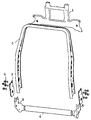
- the backrest construction shown in the drawing for the front seat of a motor vehicle includes one Backrest frame 1, a backrest head 2, one on both sides nodes 5 arranged on the underside of the backrest frame 1 and a lower one arranged between the lower nodes 5 Cross member 6.
- the components that make up the backrest construction exists can be divided into two assemblies, namely a first Assembly from the backrest frame 1 and the backrest head 2 and a second assembly from the lower nodes 5 and the cross member 6 divide.
- the backrest frame 1 consists of an extruded profile part in the form of an I-beam with variable Cross-section.
- the backrest frame 1 which has a different height can have are all base suspension points, mounting points for a side airbag etc. added.
- Identical construction of the attachments used for steel backrests is given in that the web of an I-beam resembles a sheet and the backrest frame is made of one I-beam is made.
- kneading materials As a material for the backrest frame 1 in the form of a Extruded profile part come kneading materials, in particular Aluminum alloy wrought materials with high elongation in question. The use of kneading materials with high elongation is in this for energy absorption in a rear impact primarily responsible area of a backrest important.
- the backrest head 2 is designed as a lightweight component and consists of an Al or Mg die-cast part or a plastic injection molded part. But others can too inexpensive secondary materials are used because the Loads are not that high and strains in plastic Area are not required. First and foremost is the modulus of elasticity of the material for component design at Backrest head 2 is important.
- the backrest head 2 basically has the task of Headrest guides or rods, the protection of the headrest rods, the upper base suspension points, the two-door release in two-door vehicles, the electric drive for electrical headrests, the attachment points of Trim parts on the back of the backrest and luggage fenders record if necessary for certain models is.
- the second assembly consists of the lower nodes 5 and the lower cross member 6.
- connection between node 5 and the cross member 6 consists for example of an adhesive plug connection.
- the lower cross member 6 is in the form of an extruded profile preferably again from a kneading material, for example made of an Al alloy wrought material. It is an important component in the event of an impact in the event of a side impact, the survival space protection and an impact on the rear, the energy absorption in the pool area backs up.
- the crossbeam is used for normal use of the seat 6 as torsion beam with asymmetrical load on the backrest and to accommodate the base suspension below, which is usually consists of two holes. Since it has an extruded hollow cross section has an optimal design both as Torsion beam as well as a buckling bar.
- the lower cast nodes 5 serve to connect the backrest frame 1 with the lower cross member 6, as reinforcement the connection area of the backrest recliner, as Inclusion of the base suspension, as a guide for the side pull with a two-door release and as a connection for the Electric motor with electric backrest adjuster. What the economics of different variants so the same remarks apply that in conjunction were made with the backrest head 2. If at one Casting several molded parts can also be formed in addition to knot pairs for training with adjustment of Hand at least one pair of knots for training electrical adjustment are formed.
- the first and the second assembly are form-fitting nested and with connecting elements 3, 4, which anyway to connect the backrest adjuster are connected.
- the connecting elements 4 are e.g. Rivets or screws. Because with such a mechanical fastening no welding required the otherwise occurring weakening of the material is passed on to the Avoided welds.
Landscapes
- Engineering & Computer Science (AREA)
- Aviation & Aerospace Engineering (AREA)
- Transportation (AREA)
- Mechanical Engineering (AREA)
- Seats For Vehicles (AREA)
- Body Structure For Vehicles (AREA)
Abstract
Description
Die Erfindung betrifft eine Rücklehnenkonstruktion für den Vordersitz eines Kraftfahrzeuges mit einem Lehnenrahmen, einem an der Oberseite des Lehnenrahmens angeordneten Lehnenkopf, einem auf beiden Seiten an der Unterseite des Lehnenrahmens jeweils angeordneten unteren Knoten und einem zwischen den unteren Knoten angeordneten unteren Querträger.The invention relates to a backrest construction for the front seat of a motor vehicle with a backrest frame, a backrest head arranged on the top of the backrest frame, one on both sides at the bottom of the backrest frame each arranged lower node and one lower crossbeam arranged between the lower nodes.
Auf dem Gebiet des Kraftfahrzeugbaus wird immer stärker eine Leichtbauweise eingeführt, um den Kraftstoffverbrauch so gering wie möglich zu halten. Aufgrund der unterschiedlichen Ausstattungsvarianten von Kraftfahrzeugen, z.B. einer zweitürigen, einer viertürigen Ausführung, einer Ausführung mit elektrischer oder manueller Lehnenneigungsverstellung, einer Ausführung mit elektrischem oder manuellem Kopfstützenantrieb sind zu diesen Bauteilen sehr unterschiedliche Anbindungspunkte erforderlich, die dann, wenn sie alle in der Rücklehnenkonstruktion integriert sind, zu deren Gewicht beitragen, was dem Gedanken der Leichtbauweise entgegensteht.In the field of motor vehicle construction is getting stronger a lightweight design introduced to fuel economy to keep it as low as possible. Because of the different Equipment variants of motor vehicles, e.g. one two-door, four-door version, one version with electrical or manual backrest angle adjustment, a version with electric or manual headrest drive are very different from these components Connection points required when they are all in the backrest construction are integrated, to their weight contribute what is contrary to the idea of lightweight construction.
Um die beim Einsatz von mit hohen Kosten verbundenen Leichtbauwerkstoffen entstehenden Kosten zumindest teilweise zu kompensieren, wird eine automatische Fertigung vorgesehen, um die Kosten des Zusammenbaus zu verringern.To those associated with the use of high costs Lightweight construction materials at least partially incur costs to compensate, automatic production is provided, to reduce the cost of assembly.
Wenn unterschiedliche Werkstoffe bzw. Legierungen verwandt werden, soll eine einfache Werkstofftrennung für das Recycling gegeben sein, um die Recyclingwerkstoffe weiterverwerten zu können. An der Rücklehnenkonstruktion sollen weiterhin soweit wie möglich Anbaukomponenten von in Großserie gefertigten Stahllehnen verwandt werden, die meist in Blechbauweise ausgebildet sind. Schließlich soll eine möglichst gleiche tragende Konstruktion bei unterschiedlichen Fahrzeugtypen möglich sein, um Entwicklungskosten zu sparen und die Produktionskosten optimieren zu können.If different materials or alloys are used should be a simple material separation for the Recycling is given to reuse the recycling materials to be able to. On the backrest construction as far as possible, add-on components from mass production manufactured steel backrests, which are mostly used in Sheet metal construction are formed. After all, one should if possible same supporting structure with different Vehicle types may be possible to save development costs and to be able to optimize production costs.
Die der Erfindung zugrundeliegende Aufgabe besteht daher darin, eine Rücklehnenkonstruktion der eingangs genannten Art zu schaffen, die in Leichtbauweise hergestellt werden kann und den obigen Erfordernissen soweit wie möglich genügt.The object underlying the invention is therefore in a backrest construction of the aforementioned Kind of creating that made in lightweight construction can and the above requirements as much as possible enough.
Diese Aufgabe wird gemäß der Erfindung dadurch gelöst, daß die Bauteile der Rücklehnenkonstruktion teils als Strangpreßprofile und teils als Gußteile ausgeführt sind.According to the invention, this object is achieved by that the components of the backrest construction partly as Extruded profiles and partially designed as castings.
Besonders bevorzugte Weiterbildungen und Ausgestaltungen der erfindungsgemäßen Rücklehnenkonstruktion sind Gegenstand der Patentansprüche 2 bis 7.Particularly preferred further developments and refinements the backrest construction according to the invention are the subject of claims 2 to 7.
Im folgenden wird anhand der zugehörigen Zeichnung ein besonders bevorzugtes Ausführungsbeispiel der Erfindung näher beschrieben.The following is based on the associated drawing particularly preferred embodiment of the invention described in more detail.
Die einzige Figur zeigt das Ausführungsbeispiel der erfindungsgemäßen Rücklehnenkonstruktion in einer perspektivischen auseinandergezogenen Ansicht.The only figure shows the embodiment of the backrest construction according to the invention in a perspective exploded view.
Die in der Zeichnung dargestellte Rücklehnenkonstruktion
für den Vordersitz eines Kraftfahrzeuges umfaßt einen
Lehnenrahmen 1, einen Lehnenkopf 2, einen auf beiden Seiten
an der Unterseite des Lehnenrahmens 1 angeordneten Knoten 5
sowie einen zwischen den unteren Knoten 5 angeordneten unteren
Querträger 6.The backrest construction shown in the drawing
for the front seat of a motor vehicle includes one
Backrest frame 1, a backrest head 2, one on both
Die Bauteile, aus denen die Rücklehnenkonstruktion
besteht, lassen sich in zwei Baugruppen, nämlich eine erste
Baugruppe aus dem Lehnenrahmen 1 und dem Lehnenkopf 2 sowie
eine zweite Baugruppe aus den unteren Knoten 5 und dem Querträger
6 unterteilen.The components that make up the backrest construction
exists, can be divided into two assemblies, namely a first
Assembly from the backrest frame 1 and the backrest head 2 and
a second assembly from the
In der ersten Baugruppe besteht der Lehnenrahmen 1 aus einem Strangpreßprofilteil in Form eines I-Trägers mit variablem Querschnitt.In the first assembly, the backrest frame 1 consists of an extruded profile part in the form of an I-beam with variable Cross-section.
Am Lehnenrahmen 1, der eine unterschiedliche Bauhöhe haben kann, sind alle Basisbefederungspunkte, Aufnahmepunkte für einen Seitenairbag usw. aufgenommen. Eine weitestgehende Baugleichheit der Anbauteile, die bei Stahllehnen verwendet werden, ist insofern gegeben, als der Steg eines I-Trägers einem Blech gleicht und der Lehnenrahmen aus einem derartigen I-Träger gefertigt ist.On the backrest frame 1, which has a different height can have are all base suspension points, mounting points for a side airbag etc. added. As far as possible Identical construction of the attachments used for steel backrests is given in that the web of an I-beam resembles a sheet and the backrest frame is made of one I-beam is made.
Als Werkstoff für den Lehnenrahmen 1 in Form eines Strangpreßprofilteils kommen Knetwerkstoffe, insbesondere Aluminiumlegierungsknetwerkstoffe mit hoher Dehnung in Frage. Der Einsatz von Knetwerkstoffen mit hoher Dehnung ist in diesem für die Energieabsorbierung bei einem Heckaufprall in erster Linie verantwortlichen Bereich einer Lehne besonders wichtig.As a material for the backrest frame 1 in the form of a Extruded profile part come kneading materials, in particular Aluminum alloy wrought materials with high elongation in question. The use of kneading materials with high elongation is in this for energy absorption in a rear impact primarily responsible area of a backrest important.
Der Lehnenkopf 2 ist als Leichtbaukomponente ausgebildet und besteht aus einem Al- oder Mg-Druckgußteil oder einem Kunststoffspritzgußteil. Es können aber auch andere kostengünstige Sekundärwerkstoffe eingesetzt werden, da die Belastungen nicht so hoch sind und Dehnungen im plastischen Bereich nicht gefordert sind. In erster Linie ist der Elastizitätsmodul des Werkstoffes für die Bauteilauslegung beim Lehnenkopf 2 von Bedeutung. The backrest head 2 is designed as a lightweight component and consists of an Al or Mg die-cast part or a plastic injection molded part. But others can too inexpensive secondary materials are used because the Loads are not that high and strains in plastic Area are not required. First and foremost is the modulus of elasticity of the material for component design at Backrest head 2 is important.
Zur Verbindung des Lehnenkopfes 2 mit dem Lehnenrahmen 1 werden gewindefurchende Schrauben verwendet, die in der Zeichnung nicht dargestellt sind. Diese Schrauben sind optimal automatisierbar und ermöglichen eine Kombination unterschiedlichster Werkstoffe sowie deren sortenreine Trennung.To connect the backrest head 2 to the backrest frame 1 are self-tapping screws used in the Drawing are not shown. These screws are optimal can be automated and enable a combination of the most diverse Materials and their separate separation.
Zur Verbindung des Lehnenkopfes 2 mit dem Lehnenrahmen 1 kommen auch die Verwendung von Nieten, das Durchsetzfügen oder bei Verwendung von Kunststoffteilen das Aufschmelzen von an die Kunststoffteile angespritzten Zylindern in Frage.To connect the backrest head 2 to the backrest frame 1 also use rivets, clinching or melting using plastic parts of cylinders molded onto the plastic parts.
Der Lehnenkopf 2 hat grundsätzlich die Aufgabe, die Kopfstützenführungen bzw. -stangen, den Schutz der Kopfstützenstangen, die oberen Basisbefederungspunkte, die Zweitürentriegelung bei Zweitürfahrzeugen, den Elektroantrieb bei elektrischen Kopfstützen, die Befestigungspunkte von Verkleidungsteilen der Lehnenhinterseite und Gepäckschutzbleche aufzunehmen, falls das bei bestimmten Modellen erforderlich ist.The backrest head 2 basically has the task of Headrest guides or rods, the protection of the headrest rods, the upper base suspension points, the two-door release in two-door vehicles, the electric drive for electrical headrests, the attachment points of Trim parts on the back of the backrest and luggage fenders record if necessary for certain models is.
Da die Werkzeugkosten von Formteilen wie Al-, Mg-Druckgußteilen oder Kunststoffspritzgußteilen relativ günstig sind, können in einfacher Weise unterschiedliche Varianten für zweitürige und viertürige Fahrzeuge, für Fahrzeuge mit elektrischer Kopfstütze und manueller Kopfstütze für Fahrzeuge mit Hardtrim hinten oder Sackbezug usw. hergestellt werden.Since the tooling cost of molded parts such as Al, Mg die-cast parts or plastic injection molded parts relatively cheap are different variants in a simple manner for two-door and four-door vehicles, for vehicles with electric headrest and manual headrest for vehicles made with hard trim in the back or sack cover etc. become.
Da die Werkzeugstandzeit bei solchen Teilen ca. 100.000 Abformungen beträgt, kann das als weitestgehend kostenneutral betrachtet werden.Since the tool life for such parts is approx. 100,000 Impressions, this can be as cost-neutral as possible to be viewed as.
Die zweite Baugruppe besteht aus den unteren Knoten 5
und dem unteren Querträger 6.The second assembly consists of the
Die Verbindung zwischen den Knoten 5 und dem Querträger
6 besteht beispielsweise aus einer Klebesteckverbindung.The connection between
Der untere Querträger 6 ist in Form eines Strangpreßprofils
vorzugsweise wiederum aus einem Knetwerkstoff, beispielsweise
aus einem Al-Legierungsknetwerkstoff hergestellt.
Er ist ein bei einem Aufprall wichtiges Bauteil, das
bei einem Seitenaufprall die Überlebensraumsicherung und bei
einem Aufprall auf das Heck die Energieabsorption im Beckenbereich
sichert.The
Für den Normalgebrauch des Sitzes dient der Querträger
6 als Torsionsträger bei asymmetrischer Belastung der Lehne
und zur Aufnahme der Basisbefederung unten, die in der Regel
aus zwei Löchern besteht. Da er einen stranggepreßten Hohlquerschnitt
hat, ist eine optimale Gestaltung sowohl als
Torsionsträger als auch als Knickstab gegeben.The crossbeam is used for normal use of the
Die unteren Gußknoten 5 dienen zur Verbindung des Lehnenrahmens
1 mit dem unteren Querträger 6, als Verstärkung
des Anbindungsbereiches des Lehnenneigungsverstellers, als
Aufnahme der Basisbefederung, als Führung des Seitenzuges
bei einer Zweitürentriegelung sowie als Anschluß für den
Elektromotor bei elektrischem Lehnenneigungsversteller. Was
die Wirtschaftlichkeit bei unterschiedlichen Varianten anbetrifft,
so gelten die gleichen Ausführungen, die in Verbindung
mit dem Lehnenkopf 2 gemacht wurden. Wenn bei einem
Abguß mehrere Formteile gebildet werden, kann darüber hinaus
neben Knotenpaaren für die Ausbildung mit Verstellung von
Hand auch wenigstens ein Knotenpaar für die Ausbildung mit
elektrischer Verstellung gebildet werden.The
Die erste und die zweite Baugruppe sind formschlüssig ineinandergesteckt und mit Verbindungselementen 3, 4, welche zur Anbindung des Lehnenneigungsverstellers sowieso benötigt werden, miteinander verbunden. Die Verbindungselemente 4 sind z.B. Nieten oder Schrauben. Da bei einer derartigen mechanischen Befestigung keine Schweißungen erforderlich sind, wird die sonst auftretende Materialschwächung an den Schweißnähten vermieden.The first and the second assembly are form-fitting nested and with connecting elements 3, 4, which anyway to connect the backrest adjuster are connected. The connecting elements 4 are e.g. Rivets or screws. Because with such a mechanical fastening no welding required the otherwise occurring weakening of the material is passed on to the Avoided welds.
Claims (7)
Applications Claiming Priority (2)
| Application Number | Priority Date | Filing Date | Title |
|---|---|---|---|
| DE19826732A DE19826732B4 (en) | 1998-06-16 | 1998-06-16 | Seatback design |
| DE19826732 | 1998-06-16 |
Publications (3)
| Publication Number | Publication Date |
|---|---|
| EP0965480A2 true EP0965480A2 (en) | 1999-12-22 |
| EP0965480A3 EP0965480A3 (en) | 2000-06-14 |
| EP0965480B1 EP0965480B1 (en) | 2004-09-08 |
Family
ID=7871009
Family Applications (1)
| Application Number | Title | Priority Date | Filing Date |
|---|---|---|---|
| EP99110802A Expired - Lifetime EP0965480B1 (en) | 1998-06-16 | 1999-06-04 | Backrest construction |
Country Status (3)
| Country | Link |
|---|---|
| US (1) | US6761412B1 (en) |
| EP (1) | EP0965480B1 (en) |
| DE (2) | DE19826732B4 (en) |
Cited By (5)
| Publication number | Priority date | Publication date | Assignee | Title |
|---|---|---|---|---|
| EP1186469A1 (en) * | 2000-08-28 | 2002-03-13 | Magnesium Products of Italy S.p.A. | A backrest for a motor vehicle seat, in particular for a rear seat |
| EP1228962A1 (en) * | 2001-02-05 | 2002-08-07 | Société Industrielle et Commerciale de Matériel Aéronautique | Aircraft seat element with upholstery fabric and assembly method for said element |
| CN102923028A (en) * | 2011-08-11 | 2013-02-13 | 福特环球技术公司 | Vibration damper used for seat back,vibration damping seat back, and damped system |
| WO2018069603A1 (en) | 2016-10-14 | 2018-04-19 | Psa Automobiles Sa | Multiple-position gusset plate for a vehicle seat hinge assembly |
| CN109476247A (en) * | 2016-07-21 | 2019-03-15 | 株式会社泰极爱思 | vehicle seat |
Families Citing this family (25)
| Publication number | Priority date | Publication date | Assignee | Title |
|---|---|---|---|---|
| DE10047770A1 (en) * | 2000-09-27 | 2002-04-11 | Bayerische Motoren Werke Ag | Frame structure, in particular backrest frame for a vehicle chair, comprising at least two side rails and an upper cross member connecting them, each made of hollow profiles |
| DE10048128B4 (en) * | 2000-09-28 | 2004-07-08 | Keiper Gmbh & Co. Kg | Side rail for a vehicle seat structure |
| DE10053048B4 (en) | 2000-10-13 | 2018-05-09 | Volkswagen Ag | vehicle seat |
| US7066552B2 (en) * | 2003-03-31 | 2006-06-27 | Ts Tech Co., Ltd. | Seat back frame for vehicle seat |
| KR100590947B1 (en) * | 2004-06-07 | 2006-06-19 | 현대자동차주식회사 | Magnesium Alloy Seat Back Frame for Automobile and Forming Method |
| DE102004035454B4 (en) * | 2004-07-22 | 2015-02-26 | Robert Bosch Gmbh | support element |
| DE102004044734A1 (en) * | 2004-09-15 | 2006-03-16 | Bayerische Motoren Werke Ag | Vehicle e.g. passenger car, seat, has rest and seat frames including two longitudinal chassis beams and two cross beams, where cross beams are made from light metal and chassis beams are made from ferrous material |
| US20060138830A1 (en) * | 2004-12-23 | 2006-06-29 | Cho-Hsin Liu | Barrel shaped chair of a racing car |
| DE102007016690A1 (en) | 2006-10-27 | 2008-04-30 | Johnson Controls Gmbh | Motor vehicle seat has structural element with number of components, which are connected to each other, and component is available as steel and light weight design |
| US7909407B2 (en) * | 2007-06-07 | 2011-03-22 | Lear Corporation | Vehicle seat connection |
| US7469967B1 (en) * | 2007-06-14 | 2008-12-30 | Tachi-S Co., Ltd. | Frame assembly of automotive seat |
| DE102007050091A1 (en) * | 2007-10-19 | 2009-04-23 | GM Global Technology Operations, Inc., Detroit | Vehicle seat with a rotating back section |
| JP5698980B2 (en) | 2007-10-29 | 2015-04-08 | ジョンソン・コントロールズ・ゲー・エム・ベー・ハー | Structural elements for vehicle seats |
| DE102008023943B4 (en) * | 2008-05-13 | 2012-03-15 | Keiper Gmbh & Co. Kg | Vehicle seat with fittings |
| WO2010045571A1 (en) * | 2008-10-16 | 2010-04-22 | Johnson Controls Technology Company | One-piece seat structure and cold forming processes to create seat structures |
| DE102009017373A1 (en) | 2009-04-14 | 2010-10-21 | GM Global Technology Operations, Inc., Detroit | Backrest structure for motor vehicle seat, has head restraint-side cross bar partly formed as strand profile, where strand direction of cross bar is aligned parallel to longitudinal axis of guide rod |
| DE102009042027B4 (en) | 2009-09-17 | 2023-12-07 | Volkswagen Ag | Seat structures made from basic elements manufactured by extrusion |
| EP2616272B1 (en) * | 2010-09-14 | 2017-06-21 | Basf Se | Energy absorbing bracket for a seat of a vehicle |
| DE102010049328A1 (en) * | 2010-10-19 | 2012-04-19 | Keiper Gmbh & Co. Kg | Vehicle seat, in particular motor vehicle seat |
| JP2015091712A (en) * | 2015-02-17 | 2015-05-14 | テイ・エス テック株式会社 | Vehicle seat |
| US10576857B2 (en) * | 2016-02-12 | 2020-03-03 | Adient Luxembourg Holding S.Á R.L. | Seat back frame |
| CN108119447A (en) * | 2016-11-29 | 2018-06-05 | 比亚迪股份有限公司 | Alloy in lightweight connection component and its manufacturing method, seat and vehicle |
| JP6874360B2 (en) * | 2016-12-21 | 2021-05-19 | トヨタ紡織株式会社 | Vehicle seat |
| CN108238256B (en) * | 2016-12-26 | 2022-03-18 | 中国民用航空总局第二研究所 | Novel aviation seat back skeleton |
| US10369910B1 (en) * | 2018-01-12 | 2019-08-06 | Lear Corporation | Aesthetic seat backrest panel for a motor vehicle |
Family Cites Families (18)
| Publication number | Priority date | Publication date | Assignee | Title |
|---|---|---|---|---|
| DE3821554A1 (en) * | 1988-06-22 | 1989-12-28 | Isringhausen Geb | VEHICLE SEAT WITH A BACKREST FRAME |
| DE3841532A1 (en) * | 1988-12-09 | 1990-06-13 | Bayer Ag | BACKREST SUPPORT STRUCTURE FOR A VEHICLE SEAT AND VEHICLE SEAT BACKREST WITH THIS BACKREST SUPPORT STRUCTURE |
| JPH03189109A (en) * | 1989-12-20 | 1991-08-19 | Mazda Motor Corp | Blow molding seat frame and molding method therefor |
| JPH0753556Y2 (en) * | 1990-11-26 | 1995-12-13 | 池田物産株式会社 | Back frame |
| FR2720141B1 (en) * | 1994-05-20 | 1996-08-02 | Cesa | Improved element of seat frame, part making use of it and its application in particular to a vehicle seat. |
| DE4442588C2 (en) * | 1994-11-30 | 1996-10-31 | Fahrzeugsitze Bad Schandau Gmb | Seat, in particular vehicle seat for public transport |
| AT888U1 (en) * | 1995-02-02 | 1996-07-25 | Euromotive Gmbh | SEAT FRAME FOR A MOTOR VEHICLE SEAT |
| DE19514941C2 (en) * | 1995-04-22 | 1998-06-10 | Keiper Recaro Gmbh Co | Backrest for vehicle seats, in particular motor vehicle seats |
| AT407502B (en) * | 1995-05-10 | 2001-04-25 | Euromotive Gmbh | METHOD FOR PRODUCING A U-SHAPED FRAME OF A REAR OF A MOTOR VEHICLE SEAT, THAT IS COMPOSED OF TWO LONGITUDE AND A CROSS-BAR |
| FR2735731B1 (en) * | 1995-06-20 | 1997-08-29 | Irausa Ingeniera | VEHICLE SEAT STRUCTURE INCLUDING A SEAT BELT |
| US5897168A (en) * | 1995-07-28 | 1999-04-27 | Johnson Controls Technology Company | Vehicle seat frame |
| AT406554B (en) * | 1995-09-08 | 2000-06-26 | Euromotive Gmbh | METHOD FOR PRODUCING THE FRAME OF THE BACKREST OF A MOTOR VEHICLE SEAT |
| GB9519731D0 (en) * | 1995-09-27 | 1995-11-29 | Alliedsignal Deutschland Gmbh | Airbag |
| DE19544210A1 (en) * | 1995-11-28 | 1997-06-05 | Stoll Sedus Ag | Seating with two side rails |
| DE19603946C2 (en) * | 1996-02-05 | 1998-06-04 | Daimler Benz Ag | Vehicle seat |
| DE19613164C2 (en) * | 1996-04-02 | 1998-06-10 | Keiper Recaro Gmbh Co | Backrest for vehicle seats |
| US5769499A (en) * | 1996-06-07 | 1998-06-23 | Lear Corporation | Motor vehicle seat |
| WO1998008705A1 (en) * | 1996-08-29 | 1998-03-05 | Lear Corporation | Vehicle seat assembly |
-
1998
- 1998-06-16 DE DE19826732A patent/DE19826732B4/en not_active Expired - Lifetime
-
1999
- 1999-06-04 DE DE59910430T patent/DE59910430D1/en not_active Expired - Lifetime
- 1999-06-04 EP EP99110802A patent/EP0965480B1/en not_active Expired - Lifetime
- 1999-06-10 US US09/329,229 patent/US6761412B1/en not_active Expired - Fee Related
Non-Patent Citations (1)
| Title |
|---|
| None |
Cited By (6)
| Publication number | Priority date | Publication date | Assignee | Title |
|---|---|---|---|---|
| EP1186469A1 (en) * | 2000-08-28 | 2002-03-13 | Magnesium Products of Italy S.p.A. | A backrest for a motor vehicle seat, in particular for a rear seat |
| EP1228962A1 (en) * | 2001-02-05 | 2002-08-07 | Société Industrielle et Commerciale de Matériel Aéronautique | Aircraft seat element with upholstery fabric and assembly method for said element |
| FR2820399A1 (en) * | 2001-02-05 | 2002-08-09 | Sicma Aero Seat | BACK STRUCTURE FOR AIRCRAFT SEAT WITH COVERING FABRIC AND METHOD FOR MOUNTING THE STRUCTURE |
| CN102923028A (en) * | 2011-08-11 | 2013-02-13 | 福特环球技术公司 | Vibration damper used for seat back,vibration damping seat back, and damped system |
| CN109476247A (en) * | 2016-07-21 | 2019-03-15 | 株式会社泰极爱思 | vehicle seat |
| WO2018069603A1 (en) | 2016-10-14 | 2018-04-19 | Psa Automobiles Sa | Multiple-position gusset plate for a vehicle seat hinge assembly |
Also Published As
| Publication number | Publication date |
|---|---|
| DE19826732B4 (en) | 2007-03-29 |
| DE19826732A1 (en) | 2000-01-27 |
| EP0965480B1 (en) | 2004-09-08 |
| DE59910430D1 (en) | 2004-10-14 |
| EP0965480A3 (en) | 2000-06-14 |
| US6761412B1 (en) | 2004-07-13 |
Similar Documents
| Publication | Publication Date | Title |
|---|---|---|
| EP0965480B1 (en) | Backrest construction | |
| DE102007006722C5 (en) | Carrier for a body of a motor vehicle | |
| DE4138647C2 (en) | Backrest frame for a seat | |
| DE102004062932B4 (en) | Rear floor structure of a motor vehicle | |
| DE60220252T2 (en) | FRONT ARRANGEMENT FOR HEAVY-COMMERCIAL VEHICLES | |
| EP0927653A1 (en) | Integral internal reinforcement for a door | |
| DE102012010736B4 (en) | Structure of a mounting part for vehicle rear seats | |
| EP1984205B1 (en) | Motor vehicle with a device for attaching a backrest | |
| DE102010035212A1 (en) | Body structure of a motor vehicle, motor vehicle and method for producing a body structure | |
| DE69320459T2 (en) | HIGH-STRENGTH VEHICLE SEAT FRAME AND METHOD | |
| DE102010018638B4 (en) | Vehicle with a support structure of a seat cross member | |
| DE102012023674A1 (en) | Motor vehicle with modular bodywork | |
| DE19841100C1 (en) | Rear structure of a self-supporting motor vehicle body and method for its production | |
| DE69811317T2 (en) | Bumper mounting structure for vehicles with separate chassis frames | |
| DE602004013204T2 (en) | ARRANGEMENT FOR VEHICLE CABINS | |
| DE102010048350A1 (en) | Base assembly for modular system, for multiple design variants of passenger car body, have rear drive unit, where front module and rear module are connected with each other by base assembly | |
| EP0774401B1 (en) | Front part for automotive vehicles incorporating a support structure | |
| EP0915007A2 (en) | Body structure comprising at least one transversal wall | |
| DE19746238B4 (en) | Body construction of a passenger car | |
| EP1525133B1 (en) | Floor-stiffening structure in motor vehicles | |
| DE69501759T2 (en) | Frame element for seat backrest, in particular vehicle seat backrest | |
| DE602004011271T2 (en) | SUPPORTING RACK FOR A DASHBOARD | |
| EP2374666A2 (en) | Connection assembly with at least two structural components for a motor vehicle and method for producing same | |
| DE102008055103A1 (en) | seat structure | |
| EP1646551A1 (en) | Driver's cab for a utility vehicle |
Legal Events
| Date | Code | Title | Description |
|---|---|---|---|
| PUAI | Public reference made under article 153(3) epc to a published international application that has entered the european phase |
Free format text: ORIGINAL CODE: 0009012 |
|
| AK | Designated contracting states |
Kind code of ref document: A2 Designated state(s): DE FR IT |
|
| AX | Request for extension of the european patent |
Free format text: AL;LT;LV;MK;RO;SI |
|
| PUAL | Search report despatched |
Free format text: ORIGINAL CODE: 0009013 |
|
| AK | Designated contracting states |
Kind code of ref document: A3 Designated state(s): AT BE CH CY DE DK ES FI FR GB GR IE IT LI LU MC NL PT SE |
|
| AX | Request for extension of the european patent |
Free format text: AL;LT;LV;MK;RO;SI |
|
| 17P | Request for examination filed |
Effective date: 20000807 |
|
| AKX | Designation fees paid |
Free format text: DE FR IT |
|
| GRAP | Despatch of communication of intention to grant a patent |
Free format text: ORIGINAL CODE: EPIDOSNIGR1 |
|
| GRAS | Grant fee paid |
Free format text: ORIGINAL CODE: EPIDOSNIGR3 |
|
| GRAA | (expected) grant |
Free format text: ORIGINAL CODE: 0009210 |
|
| AK | Designated contracting states |
Kind code of ref document: B1 Designated state(s): DE FR IT |
|
| REF | Corresponds to: |
Ref document number: 59910430 Country of ref document: DE Date of ref document: 20041014 Kind code of ref document: P |
|
| RAP2 | Party data changed (patent owner data changed or rights of a patent transferred) |
Owner name: EUROMOTIVE GMBH & CO. KG |
|
| PG25 | Lapsed in a contracting state [announced via postgrant information from national office to epo] |
Ref country code: IT Free format text: LAPSE BECAUSE OF NON-PAYMENT OF DUE FEES Effective date: 20050604 |
|
| PLBE | No opposition filed within time limit |
Free format text: ORIGINAL CODE: 0009261 |
|
| STAA | Information on the status of an ep patent application or granted ep patent |
Free format text: STATUS: NO OPPOSITION FILED WITHIN TIME LIMIT |
|
| ET | Fr: translation filed | ||
| 26N | No opposition filed |
Effective date: 20050609 |
|
| REG | Reference to a national code |
Ref country code: FR Ref legal event code: TP |
|
| PGRI | Patent reinstated in contracting state [announced from national office to epo] |
Ref country code: IT Effective date: 20091201 |
|
| PGFP | Annual fee paid to national office [announced via postgrant information from national office to epo] |
Ref country code: FR Payment date: 20100622 Year of fee payment: 12 |
|
| PGFP | Annual fee paid to national office [announced via postgrant information from national office to epo] |
Ref country code: IT Payment date: 20100621 Year of fee payment: 12 |
|
| PGFP | Annual fee paid to national office [announced via postgrant information from national office to epo] |
Ref country code: DE Payment date: 20100630 Year of fee payment: 12 |
|
| PG25 | Lapsed in a contracting state [announced via postgrant information from national office to epo] |
Ref country code: IT Free format text: LAPSE BECAUSE OF NON-PAYMENT OF DUE FEES Effective date: 20110604 |
|
| REG | Reference to a national code |
Ref country code: FR Ref legal event code: ST Effective date: 20120229 |
|
| REG | Reference to a national code |
Ref country code: DE Ref legal event code: R119 Ref document number: 59910430 Country of ref document: DE Effective date: 20120103 |
|
| PG25 | Lapsed in a contracting state [announced via postgrant information from national office to epo] |
Ref country code: FR Free format text: LAPSE BECAUSE OF NON-PAYMENT OF DUE FEES Effective date: 20110630 Ref country code: DE Free format text: LAPSE BECAUSE OF NON-PAYMENT OF DUE FEES Effective date: 20120103 |