EP0965542A2 - Installation de lavage pour conteneur à ordures - Google Patents
Installation de lavage pour conteneur à ordures Download PDFInfo
- Publication number
- EP0965542A2 EP0965542A2 EP99304621A EP99304621A EP0965542A2 EP 0965542 A2 EP0965542 A2 EP 0965542A2 EP 99304621 A EP99304621 A EP 99304621A EP 99304621 A EP99304621 A EP 99304621A EP 0965542 A2 EP0965542 A2 EP 0965542A2
- Authority
- EP
- European Patent Office
- Prior art keywords
- bin
- washing
- water
- assembly
- refuse bin
- Prior art date
- Legal status (The legal status is an assumption and is not a legal conclusion. Google has not performed a legal analysis and makes no representation as to the accuracy of the status listed.)
- Withdrawn
Links
- 238000005406 washing Methods 0.000 title claims abstract description 48
- XLYOFNOQVPJJNP-UHFFFAOYSA-N water Substances O XLYOFNOQVPJJNP-UHFFFAOYSA-N 0.000 claims description 33
- 239000002351 wastewater Substances 0.000 claims description 17
- 238000004064 recycling Methods 0.000 claims description 3
- 239000007921 spray Substances 0.000 claims description 2
- 238000005507 spraying Methods 0.000 claims description 2
- 210000000078 claw Anatomy 0.000 description 4
- 239000002184 metal Substances 0.000 description 2
- 239000002699 waste material Substances 0.000 description 2
- 241000189524 Baccharis halimifolia Species 0.000 description 1
- 230000004888 barrier function Effects 0.000 description 1
- 238000004140 cleaning Methods 0.000 description 1
- 238000001914 filtration Methods 0.000 description 1
- 239000013505 freshwater Substances 0.000 description 1
- 230000000717 retained effect Effects 0.000 description 1
- 239000002910 solid waste Substances 0.000 description 1
Images


Classifications
-
- B—PERFORMING OPERATIONS; TRANSPORTING
- B65—CONVEYING; PACKING; STORING; HANDLING THIN OR FILAMENTARY MATERIAL
- B65F—GATHERING OR REMOVAL OF DOMESTIC OR LIKE REFUSE
- B65F7/00—Cleaning or disinfecting devices combined with refuse receptacles or refuse vehicles
- B65F7/005—Devices, mounted on refuse collecting vehicles, for cleaning or disinfecting refuse receptacles
Definitions
- the present invention relates to an apparatus for washing refuse bins.
- My washing apparatus is built into the covered rear of a road truck or van and includes an elevated slide which is inclined rearwardly and positioned to one side of the van body.
- each bin is inverted and placed on the slide, with its front wall facing downwardly and supported on the slide and its top end facing outwardly and downwardly, towards the rear of the van. In this position, the lid is folded upwardly and rearwardly onto the rear wall of the bin.
- a water jet and a water brush are provided, fed via a pump with washing water from an on-board tank, for washing the inside of the bin. Thereafter, the bin is slid sidewardly off the inclined slide, to stand upright on a deck, where its outside is washed. Finally, the bin is lifted onto the ground and a fresh bin liner is fitted into it. The waste water, from the washing operation, drains into a reservoir, for disposal at a later time.
- each bin is lifted manually into the rear of the van and onto the slide. This is quite strenuous work, because the bin is relatively large and cumbersome and the apparatus is designed for cleaning a large number of the bins in a day, so that the operator is required to handle a correspondingly large number of bins.
- a refuse bin washing apparatus which comprises an elevated, inclined support for a refuse bin to be washed, and a lifting assembly for lifting a refuse bin from the ground and onto said inclined support, the lifting assembly comprising a structure mounted for pivoting about a horizontal axis, transverse to said inclined support, said structure having means for engaging and supporting the refuse bin, the lifting assembly being arranged so that upon turning said structure about its axis of pivoting, the bin is lifted and turned until its rear wall lies on said support and its top faces outwardly.
- the supporting means of the lifting assembly may be arranged to engage the refuse bin at or adjacent the bottom rear edge of the bin.
- the supporting means comprises a pair of rearwardly-projecting elements which have recesses to receive the axles of two rear wheels of the refuse bin.
- the pivoted structure comprises an upright arm having a horizontally-projecting member which carries the supporting means for engaging the refuse bin at or adjacent its bottom rear edge.
- the upright arm of the pivoted structure has a horizontally-projecting shaft at or adjacent its upper end, engaged in bearing means which provide for the pivoting action of the arm.
- the means for supporting the bin may be arranged to engage the pivot pins of the lid of the bin.
- These means may be in the form of hooks carried by a member positioned parallel to but spaced from the axis of pivoting of the pivoted structure.
- the inclined support or support slide for the refuse bin is positioned above a horizontal deck and adjacent one side of this deck.
- the side edge of the slide is angled such that the slide is narrower at its lower end, so facilitating the sliding of the refuse bin off the slide over one of its sides and onto the deck, so that the bin comes to rest in an upright position alongside the slide.
- a water-spraying nozzle is provided adjacent the top of the support slide, for washing the bottom of the refuse bin.
- a switch is provided adjacent the top of the support slide and is depressible upon sliding the bin up the slide, to operate the water spray.
- a trough is provided at the lower end of the support slide, to receive waste water when washing the interior of the refuse bin.
- waste water in this trough drains into a reservoir.
- waste water is also able to drain through the horizontal deck and into the reservoir.
- the pivoted structure of the lifting assembly may be arranged for pivoting upwardly in manual manner.
- a pulley arrangement may be provided to assist in pivoting this structure upwardly.
- a powered drive unit may be provided for pivoting this structure.
- a refuse bin washing apparatus which comprises a tank for storing a supply of water, means for drawing water from said tank for washing successive refuse bins, means for collecting the water used to wash the bins, and means for recycling at least part of the used water back to the supply tank.
- the water collecting means is arranged to collect the water which has been used to wash the interior of the bin separately from the water which has been used to wash the exterior of the bin.
- the waste water from the outsides of the bins is only moderately dirty and can be recycled, preferably via one or more filtering stages.
- the waste water from the insides of the bins is often particularly dirty: preferably therefore, the collecting means is arranged to store the waste water from the insides of the bins, for dumping at a subsequent time.
- means are provided to enable the waste water from the insides of the bins to be recycled, if desired.
- a barrier may be provided which can be removed to allow the waste water from the insides of the bins to flow to a pump chamber which is arranged for recycling the waste water from the outsides of the bins.
- a bin washing apparatus built into the open rear of a covered truck or van the van has a roof R and its open rear end (indicated by line E in Figure 1) is provided with a roller shutter closure (not shown).
- the van is formed with a low-level platform 10 at its rear and, inwardly of this, a deck 12 at a higher level.
- the slide 14 is made up of a series of metal bars extending from front to rear, the metal bar 14a at the left hand edge of the slide extending along an angled line such that the slide 14 is narrower at its rear end than at its front end.
- a trough 16 extends across the van in front of the slide 14 and its rear wall 16a is perforated to form a filter.
- the deck 12 is also perforated to form a filter and the space below the deck 12 is enclosed to form a reservoir 18 for waste water: this reservoir 18 is provided with a dump valve 19.
- the apparatus of Figures 1 and 2 is fitted with a lifting assembly for lifting a refuse bin from the ground and onto the slide 14.
- the lifting assembly is shown in Figures 1 and 3 and comprises an arm 20 mounted for pivoting about its upper end: thus, the arm 20 has a shaft 21 projecting at right angles from its upper end and engaged in bearing brackets 22 which are fixed to the top of the rear wall 16b of the trough 16. Adjacent its lower end, the pivoted arm 20 has a rod 24 extending from it at right angles, the rod 24 carrying a pair of rearwardly-projecting claws 25 in the form of flat plates having recesses 26 open to their rear edges.
- the lifting arm 20 For lifting a refuse bin W from the ground G and onto the slide 14, the lifting arm 20 is initially in its lowered position, shown in Figure 1.
- the refuse bin is wheeled rearwardly towards the lifting assembly, and then tilted slightly forwardly to engage the axles of its wheels into the recesses 26 of the claws 25.
- the refuse bin W is then tilted rearwardly, pivoting about its axles engaged with the claws 25, to rest its rear against the top of the wall 16b.
- the operator turns the arm 20 upwardly about the rotational axis formed by its shaft 21: to achieve this, the operator may grip the projecting lower end of the arm 20 and lift it; alternatively, a pulley arrangement may be provided, including a line attached to the projecting lower end of the arm 20 via a hole 20a.
- the arm 20 is rotated until the bin W is lifted and turned right over until its rear rests on the slide 14, its top facing rearwardly: the arm 20 is returned to its lowered position, the claws 25 being disengaged from the bin W when the bin is in an intermediate position, inverted and projecting more or less vertically upwards.
- the apparatus also includes a wash jet (not shown) fitted to a flexible hose and a washing brush fitted to another flexible water hose: both hoses are fed, by means of a pump, with waste water from an on-board water tank.
- the wash jet and washing brush are used to wash the interior of the bin W.
- the bin is slid bottom-first towards the right and over the left-hand edge of the slide 14, so that it comes to rest in upright position on the deck 12, to the right of the slide 14.
- the wash jet and washing brush are now used to wash the exterior of the bin, the bin being turned around on the deck 12 as necessary.
- the lifting assembly for the refuse bin greatly facilitates the transfer of each bin from the ground and into the required position on the slide 12.
- Figure 4 shows a modified lifting assembly, in which the arm 20 is formed in two parts, a relatively short upper part 20b and a relatively long lower part 20c, which are coupled together end-to-end.
- a bar 28 projects at right angles from the upper part 20b, adjacent its lower end, and parallel to the pivot shaft 21: the bar 28 has a pair of spaced-apart hooks 29 fixed to it.
- the modified lifting assembly of Figure 4 may be used in exactly the same way as described above for the lifting assembly shown in Figures 1 and 3: however, it may instead be used in the following manner.
- the lower part 20c of the arm may be detached: then a refuse bin can be wheeled up to the assembly and the pivot pins of its lid engaged onto the hooks 29; then the user can lift the bin and turn the bin, together with the lifting assembly, around the axis of the pivot shaft 21, so that the bin comes to rest with its rear flat on the slide 14 of the washing apparatus.
- a powered motor may be installed for turning the assembly about its pivot axis.
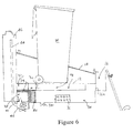
- FIGS. 5 and 6 show a modified embodiment of the bin washing apparatus.
- the perforated deck 12 has a compartment 18 below it, communicating via a perforated end wall 30 with a tank 32.
- a compartment 34 is provided under the compartment 18, to receive wash water from the trough 16 via a perforated lower portion of the rear wall 16a of the trough.
- the lower compartment 34 received water which has been used to wash to interior of the bin W when rested on the slide 14: the compartment 34 includes an agitator 36 in the form of a box having perforated walls, fixed to the floor of the compartment; in use, the agitator 36 serves to separate solid waste matter from the water.
- a dump valve 37 is provided in the floor of the lower compartment 34, to discharge waste at a convenient time.
- the tank 32 includes a chamber 38 into which water passes, from the upper compartment 18, via a filter 39.
- a closure plate 40 separates the lower compartment 34 from the chamber 38 but may be removed to allow water to flow from the compartment 34 into the chamber 38, via the filter 39.
- a pump chamber 42 is positioned below the chamber 38: a stand pipe 41 on the floor of the chamber 38 forms the inlet to the pump chamber 42 and acts to trap silt within the chamber 38 and prevent it entering the pump chamber 42.
- An outlet pipe 44 from the pump chamber 42 returns the filtered water to the on-board water tank 46 of the vehicle.
- waste water from washing the interior of the bin may be particularly dirty and therefore preferably retained in the lower compartment 34 for subsequent dumping (Figure 5).
- the waste water from washing the exterior of the bin may be only moderately dirty and therefore capable of being filtered and recycled to the on-board water tank (Figure 6).
Landscapes
- Engineering & Computer Science (AREA)
- Mechanical Engineering (AREA)
- Refuse Collection And Transfer (AREA)
Applications Claiming Priority (4)
| Application Number | Priority Date | Filing Date | Title |
|---|---|---|---|
| GBGB9812569.3A GB9812569D0 (en) | 1998-06-12 | 1998-06-12 | Refuse bin washing apparatus |
| GB9812569 | 1998-06-12 | ||
| GB9822587 | 1998-10-19 | ||
| GB9822587A GB2339677A (en) | 1998-06-12 | 1998-10-19 | Refuse bin washing apparatus |
Publications (2)
| Publication Number | Publication Date |
|---|---|
| EP0965542A2 true EP0965542A2 (fr) | 1999-12-22 |
| EP0965542A3 EP0965542A3 (fr) | 2000-01-05 |
Family
ID=26313843
Family Applications (1)
| Application Number | Title | Priority Date | Filing Date |
|---|---|---|---|
| EP99304621A Withdrawn EP0965542A3 (fr) | 1998-06-12 | 1999-06-14 | Installation de lavage pour conteneur à ordures |
Country Status (1)
| Country | Link |
|---|---|
| EP (1) | EP0965542A3 (fr) |
Cited By (3)
| Publication number | Priority date | Publication date | Assignee | Title |
|---|---|---|---|---|
| US6458112B1 (en) | 1997-12-05 | 2002-10-01 | The Procter & Gamble Company | Compound sanitary napkin having flaps and zone of extensibility |
| WO2006099680A1 (fr) * | 2005-03-24 | 2006-09-28 | Genetech Pty Ltd | Appareil de nettoyage de poubelle |
| WO2011061097A1 (fr) | 2009-11-19 | 2011-05-26 | Unitec S.P.A. | Installation pour laver des cageots utilisés pour des produits de légumes |
Family Cites Families (3)
| Publication number | Priority date | Publication date | Assignee | Title |
|---|---|---|---|---|
| FR2508855B1 (fr) * | 1981-07-01 | 1986-01-31 | Petrolieres Et | Vehicule de lavage de conteneurs, notamment de conteneurs pour la collecte mecanisee d'ordures menageres |
| GB2283409B (en) * | 1993-11-03 | 1997-02-05 | Gary Ian Paul | Refuse container cleaning |
| GB2301022A (en) * | 1995-05-24 | 1996-11-27 | Binbusters | Apparatus for cleaning containers |
-
1999
- 1999-06-14 EP EP99304621A patent/EP0965542A3/fr not_active Withdrawn
Cited By (4)
| Publication number | Priority date | Publication date | Assignee | Title |
|---|---|---|---|---|
| US6458112B1 (en) | 1997-12-05 | 2002-10-01 | The Procter & Gamble Company | Compound sanitary napkin having flaps and zone of extensibility |
| WO2006099680A1 (fr) * | 2005-03-24 | 2006-09-28 | Genetech Pty Ltd | Appareil de nettoyage de poubelle |
| WO2011061097A1 (fr) | 2009-11-19 | 2011-05-26 | Unitec S.P.A. | Installation pour laver des cageots utilisés pour des produits de légumes |
| US9415429B2 (en) | 2009-11-19 | 2016-08-16 | Unitec S.P.A. | Plant for cleaning bins used for vegetable produce |
Also Published As
| Publication number | Publication date |
|---|---|
| EP0965542A3 (fr) | 2000-01-05 |
Similar Documents
| Publication | Publication Date | Title |
|---|---|---|
| US4348783A (en) | Scrubbing machine with selective recycle | |
| US6132509A (en) | Transportable wash and paint facility | |
| US8313584B1 (en) | Vehicle mounted garbage can cleaner and method | |
| US3404470A (en) | Automotive trucks used by street and highway departments | |
| US3613915A (en) | Garbage collection system | |
| US8776304B2 (en) | Self-evacuating vacuum device | |
| CA1162360A (fr) | Chariot extracteur de debris | |
| US6129117A (en) | Portable holding tank | |
| US8012265B2 (en) | Concrete/asphalt wet washing system | |
| US3324866A (en) | Sanitation system | |
| US9943982B2 (en) | Concrete mixing transport truck chute washout system | |
| CA2061961A1 (fr) | Vehicule servant au nettoyage des citernes intermediaires | |
| US10350651B2 (en) | Apparatus and method for cleaning trash containers | |
| WO2008124862A1 (fr) | Installation mobile de lavage de véhicule | |
| US3193867A (en) | Street cleaning apparatus | |
| GB2283409A (en) | Washing refuse bins | |
| EP0965542A2 (fr) | Installation de lavage pour conteneur à ordures | |
| GB2348119A (en) | Transportable vehicle washing apparatus | |
| GB2339677A (en) | Refuse bin washing apparatus | |
| GB2301022A (en) | Apparatus for cleaning containers | |
| US20080035176A1 (en) | Automated Cart and Container Cleaning System | |
| US20250326576A1 (en) | Container assembly having residential refuse bin washer system for a front load refuse collection vehicle | |
| US20110139179A1 (en) | Concrete/Asphalt Wet Washing System | |
| US9670071B2 (en) | Method and apparatus for wash water treatment | |
| US12233573B2 (en) | Concrete residue collection system for concrete mixing trucks |
Legal Events
| Date | Code | Title | Description |
|---|---|---|---|
| PUAI | Public reference made under article 153(3) epc to a published international application that has entered the european phase |
Free format text: ORIGINAL CODE: 0009012 |
|
| PUAL | Search report despatched |
Free format text: ORIGINAL CODE: 0009013 |
|
| AK | Designated contracting states |
Kind code of ref document: A2 Designated state(s): AT BE CH CY DE DK ES FI FR GB GR IE IT LI LU MC NL PT SE |
|
| AX | Request for extension of the european patent |
Free format text: AL;LT;LV;MK;RO;SI |
|
| AK | Designated contracting states |
Kind code of ref document: A3 Designated state(s): AT BE CH CY DE DK ES FI FR GB GR IE IT LI LU MC NL PT SE |
|
| AX | Request for extension of the european patent |
Free format text: AL;LT;LV;MK;RO;SI |
|
| AKX | Designation fees paid | ||
| REG | Reference to a national code |
Ref country code: DE Ref legal event code: 8566 |
|
| STAA | Information on the status of an ep patent application or granted ep patent |
Free format text: STATUS: THE APPLICATION IS DEEMED TO BE WITHDRAWN |
|
| 18D | Application deemed to be withdrawn |
Effective date: 20000706 |