EP0965551A2 - Vorrichtung zum Falzen von Druck- oder Papierprodukten - Google Patents
Vorrichtung zum Falzen von Druck- oder Papierprodukten Download PDFInfo
- Publication number
- EP0965551A2 EP0965551A2 EP99890193A EP99890193A EP0965551A2 EP 0965551 A2 EP0965551 A2 EP 0965551A2 EP 99890193 A EP99890193 A EP 99890193A EP 99890193 A EP99890193 A EP 99890193A EP 0965551 A2 EP0965551 A2 EP 0965551A2
- Authority
- EP
- European Patent Office
- Prior art keywords
- section
- rollers
- conveying
- conveyor
- conveyor belts
- Prior art date
- Legal status (The legal status is an assumption and is not a legal conclusion. Google has not performed a legal analysis and makes no representation as to the accuracy of the status listed.)
- Withdrawn
Links
Images

Classifications
-
- B—PERFORMING OPERATIONS; TRANSPORTING
- B65—CONVEYING; PACKING; STORING; HANDLING THIN OR FILAMENTARY MATERIAL
- B65H—HANDLING THIN OR FILAMENTARY MATERIAL, e.g. SHEETS, WEBS, CABLES
- B65H45/00—Folding thin material
- B65H45/12—Folding articles or webs with application of pressure to define or form crease lines
- B65H45/22—Longitudinal folders, i.e. for folding moving sheet material parallel to the direction of movement
-
- B—PERFORMING OPERATIONS; TRANSPORTING
- B65—CONVEYING; PACKING; STORING; HANDLING THIN OR FILAMENTARY MATERIAL
- B65H—HANDLING THIN OR FILAMENTARY MATERIAL, e.g. SHEETS, WEBS, CABLES
- B65H2301/00—Handling processes for sheets or webs
- B65H2301/30—Orientation, displacement, position of the handled material
- B65H2301/33—Modifying, selecting, changing orientation
- B65H2301/332—Turning, overturning
- B65H2301/3321—Turning, overturning kinetic therefor
- B65H2301/33212—Turning, overturning kinetic therefor about an axis parallel to the direction of displacement of material
-
- B—PERFORMING OPERATIONS; TRANSPORTING
- B65—CONVEYING; PACKING; STORING; HANDLING THIN OR FILAMENTARY MATERIAL
- B65H—HANDLING THIN OR FILAMENTARY MATERIAL, e.g. SHEETS, WEBS, CABLES
- B65H2301/00—Handling processes for sheets or webs
- B65H2301/40—Type of handling process
- B65H2301/44—Moving, forwarding, guiding material
- B65H2301/442—Moving, forwarding, guiding material by acting on edge of handled material
- B65H2301/4422—Moving, forwarding, guiding material by acting on edge of handled material with guide member moving in the material direction
Definitions
- the present invention relates to a device for Folding printed or paper products, with two neighboring ones co-rotating conveyor belts circulating between end rollers and a conveyor run running in the direction of conveyance and one have a return run running in the reverse direction.
- the invention is an extension and improvement of Devices described above.
- the task lies with her Reason, the products better during folding and turning keep more accurate, and therefore higher working speeds too allow. Furthermore, the option of a horizontal levy should after folding a multi-layered further processing with Standard devices are made possible.
- a device for folding printed or paper products which is characterized according to the invention by a plurality of form rollers which follow one another in a line and lie opposite a first section of the conveying strands and have an approximately V-shaped convex peripheral surface with an axial section have decreasing apex angle in the conveying direction from roll to roll, and a plurality of pressure rollers which bear against the side of each conveyor strand facing away from the roller and press the conveyor strands against the top of the rollers on both sides of the top and against each other in a subsequent second section.
- two continuous conveyor belts are provided, which the Keep products safe.
- the conveyor belts press during the folding process the products on the left and right are becoming increasingly pointed Roll.
- the contact pressure is generated using pairs of rollers, whose axes are inclined. This arrangement of roles results a better and more precise hold than between pairs of rollers horizontal axes.
- a particularly advantageous embodiment of the invention is characterized in that two each on one and on other conveyor belt adjacent, forming a pair of pressure rollers have mutually parallel axes in said second section, with the axes of successive pairs of pairs too Pair are progressively rotated around the conveying direction.
- the folded products can easily move in that direction rotated or turned over, which for further processing is required, e.g. for stacking devices such as Stacker or the like
- each pressure roller pair on one Carrier is mounted, which in a rotational movement, their Midpoint between the pressure rollers, adjustable is. This enables easy adjustment of the rollers.
- the conveyor belts preferably run on their in the first section end lying around a common end roll so that only a single drive element is required.
- the tapes could also be divided and accordingly multiple drives can be provided.
- continuous Conveyor belts became a special form of belt return developed.
- preferred embodiment have the first pressure rollers of the first section and the last pressure rollers of the second section horizontal Axes on. This makes the device particularly easy easily in connection with standard devices available on the market operate which work with horizontal product flows.
- the feed gap between the first form roller and the first section of the funding dreams another conveyor belt upstream for feeding the feed gap with products, above which laterally vibrating belts for side alignment of the products transported on it are arranged. So that is it is possible to fold exactly at right angles.
- This modular structure makes the invention versatile.
- the conveyor belt 3 guides the products 1 to a feed nip 7 to which between conveyor belts 5, 6 on the one hand and the first a plurality of form rollers 9 on the other hand is.
- the conveyor belts 5, 6 run in a first section a gradually from a horizontal starting direction to one vertical direction, and in a second section b from the vertical direction using the conveyor belt 5 around 90 ° in the horizontal direction, however, with further use the conveyor belt 6 by a further 90 ° into a position turned by 180 °, in a ultimately horizontal, but one above the other Arrangement.
- Each conveyor belt 5, 6 has one running in the conveying direction Conveyor run and a return run running in the reverse direction, which are not specifically designated in the drawing.
- the form rollers 9, which the conveyor belt of the conveyor belts 5, 6 opposite in the first section a are essentially in a line in a row.
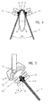
- One of the middle form rolls 9 is shown in section in FIG. 4.
- the first form roller 9 seen in the conveying direction 2 has an essentially plane, i.e. cylindrical peripheral surface 9 ', whereas the subsequent shaping rolls 9 increasingly have more pointed, V-shaped convex peripheral surface 9 ', as in FIG Fig. 4 can be seen.
- the last form roll 9 of section a is very small.
- the pressure rollers 13 in section b are thus in pairs arranged, and each pair 13, 13 is opposite to the vertical rotated by a larger angle 14 (Fig. 5) than the previous one Pair.
- each pair is on a support 12 stored, which is in a rotational movement, its center has between the pressure rollers 13, is adjustable.
- the carrier 12 has a curved slot 12 ' in which a locking screw 15 engages, which in one Not shown frame of the device mounted is.
- the conveyor belts 5, 6 run on their in the first section a lying end around a common end roller 19, and its end at the end of section b by separate, end rolls 16 one above the other 16. Press the end rolls 16 again the fold of the folded product 1 when leaving the Device and also serve as drive rollers.
- the Products 1 leave the device folded and horizontal Location.
- the Products 1 additionally between on the sides of the product edges extending sliding guides 18, such as rails, standing belts and the like guided. This is particularly the case with large, unstable products important (see Fig. 3).
- Fig. 2 is the return of the return run of the conveyor belts 5, 6 shown. After the deflection around the end roller 16 the return run of the conveyor belt 5 simply becomes the end roll 19 returned. The return run of the conveyor belt 6, however, must can still be turned by a roll 20 by 180 ° before it is turned same end roller 19 can reach. The end roller 19 also becomes Tensioning the conveyor belts 5, 6 used.
Landscapes
- Folding Of Thin Sheet-Like Materials, Special Discharging Devices, And Others (AREA)
- Delivering By Means Of Belts And Rollers (AREA)
- Separation, Sorting, Adjustment, Or Bending Of Sheets To Be Conveyed (AREA)
Abstract

Description
eine Mehrzahl von Anpreßrollen, die an der formrollenabgewandten Seite jedes Fördertrumes anliegen und die Fördertrume in dem genannten ersten Abschnitt gegen die Formrollen beidseits deren Scheitel und in einem darauffolgenden zweiten Abschnitt gegeneinander pressen.
Claims (8)
- Vorrichtung zum Falzen von Druck- oder Papierprodukten, mitzwei benachbarten gleichläufigen Förderbändern, die zwischen Endrollen umlaufen und jeweils ein in Förderrichtung laufendes Fördertrum und ein in Rückrichtung laufendes Rücklauftrum haben, gekennzeichnet durcheine Mehrzahl von in einer Linie aufeinanderfolgenden Formrollen (9), die einem ersten Abschnitt (a) der Fördertrume gegenüberliegen und eine im Axialschnitt (Fig. 4) etwa V-förmig konvexe Umfangsfläche (9') mit einem in Förderrichtung (2) von Rolle (9) zu Rolle (9) abnehmenden Scheitelwinkel (10) aufweisen, undeine Mehrzahl von Anpreßrollen (8, 11, 13), die an der formrollenabgewandten Seite jedes Fördertrumes anliegen und die Fördertrume in dem genannten ersten Abschnitt (a) gegen die Formrollen (9) beidseits deren Scheitel (9") und in einem darauffolgenden zweiten Abschnitt (b) gegeneinander pressen.
- Vorrichtung nach Anspruch 1, dadurch gekennzeichnet, daß je zwei jeweils am einen und am anderen Förderband (5, 6) anliegende, ein Paar bildende Anpreßrollen (13) im genannten zweiten Abschnitt (b) zueinander parallele Achsen aufweisen, wobei die Achsen aufeinanderfolgender Paare (13, 13) von Paar zu Paar fortschreitend um die Förderrichtung (2) gedreht (14) sind.
- Vorrichtung nach Anspruch 2, dadurch gekennzeichnet, daß jedes Anpreßrollenpaar (13, 13) auf einem Träger (12) gelagert ist, welcher in einer Drehbewegung (14), die ihren Mittelpunkt etwa zwischen den Anpreßrollen (13) hat, einstellbar ist.
- Vorrichtung nach einem der Ansprüche 1 bis 3, dadurch gekennzeichnet, daß neben den Förderbändern (5, 6) zusätzlich Gleitführungen (18), wie Schienen, stehende Bänder od.dgl., für die Produkte (1) verlaufen.
- Vorrichtung nach einem der Ansprüche 1 bis 4, dadurch gekennzeichnet, daß die Förderbänder (5, 6) an ihrem im ersten Abschnitt (a) liegenden Ende um eine gemeinsame Endrolle (19) umlaufen.
- Vorrichtung nach einem der Ansprüche 1 bis 5, dadurch gekennzeichnet, daß die ersten Anpreßrollen (8) des ersten Abschnittes (a) und die letzten Anpreßrollen (13) des zweiten Abschnittes (b) horizontale Achsen aufweisen.
- Vorrichtung nach einem der Ansprüche 1 bis 6, dadurch gekennzeichnet, daß dem Einzugspalt (7) zwischen erster Formrolle (9) und erstem Abschnitt (a) der Fördertrume ein weiteres Förderband (3) zur Beschickung des Einzugspaltes mit Produkten (1) vorgeordnet ist, oberhalb welchem seitlich vibrierende Bänder (4) zur Seitenausrichtung der darauf beförderten Produkte (1) angeordnet sind.
- Vorrichtung nach einem der Ansprüche 1 bis 7, dadurch gekennzeichnet, daß ihr ein Vereinzelungsförderer mit in Förderrichtung zunehmend schneller laufenden Rollen oder Förderbändern zwecks Vereinzelung eines schuppenförmig angelieferten Produktstromes vorgeschaltet und/oder ein Schuppenleger mit in Förderrichtung zunehmend langsamer laufenden Rollen oder Förderbändern zwecks in Schuppenform Legen des austretenden Produktstromes nachgeschaltet sind/ist.
Applications Claiming Priority (2)
| Application Number | Priority Date | Filing Date | Title |
|---|---|---|---|
| AT103498A AT406256B (de) | 1998-06-16 | 1998-06-16 | Vorrichtung zum falzen von druck- oder papierprodukten |
| AT103498 | 1998-06-16 |
Publications (2)
| Publication Number | Publication Date |
|---|---|
| EP0965551A2 true EP0965551A2 (de) | 1999-12-22 |
| EP0965551A3 EP0965551A3 (de) | 2000-05-17 |
Family
ID=3505206
Family Applications (1)
| Application Number | Title | Priority Date | Filing Date |
|---|---|---|---|
| EP99890193A Withdrawn EP0965551A3 (de) | 1998-06-16 | 1999-06-16 | Vorrichtung zum Falzen von Druck- oder Papierprodukten |
Country Status (2)
| Country | Link |
|---|---|
| EP (1) | EP0965551A3 (de) |
| AT (1) | AT406256B (de) |
Cited By (3)
| Publication number | Priority date | Publication date | Assignee | Title |
|---|---|---|---|---|
| WO2011014968A1 (de) * | 2009-08-03 | 2011-02-10 | Ferag Ag | Falzaggregat und verfahren zum falzen eines schuppenstroms von produkten |
| EP2674376A3 (de) * | 2012-06-13 | 2014-09-24 | Goss International Americas, Inc. | Vorrichtung und Verfahren zum Ausrichten und Transportieren von Druckprodukten |
| CN106276391A (zh) * | 2016-08-16 | 2017-01-04 | 赵晓旭 | 用于集藏册卡书折页的折纸方法及折纸机 |
Family Cites Families (4)
| Publication number | Priority date | Publication date | Assignee | Title |
|---|---|---|---|---|
| DE571796C (de) * | 1931-09-22 | 1933-03-06 | Brehmer Geb | Verfahren zum Falzen von Bogen oder Lagen |
| US3748937A (en) * | 1971-07-01 | 1973-07-31 | Longford Equip Intern Ltd | Card scoring device |
| US4795416A (en) * | 1983-05-24 | 1989-01-03 | Sequa Corporation | Apparatus for C-folding paper with variable spacing |
| US4747817A (en) * | 1986-07-03 | 1988-05-31 | Newsome John R | High speed signature manipulating apparatus |
-
1998
- 1998-06-16 AT AT103498A patent/AT406256B/de not_active IP Right Cessation
-
1999
- 1999-06-16 EP EP99890193A patent/EP0965551A3/de not_active Withdrawn
Cited By (4)
| Publication number | Priority date | Publication date | Assignee | Title |
|---|---|---|---|---|
| WO2011014968A1 (de) * | 2009-08-03 | 2011-02-10 | Ferag Ag | Falzaggregat und verfahren zum falzen eines schuppenstroms von produkten |
| CH701622A1 (de) * | 2009-08-03 | 2011-02-15 | Ferag Ag | Falzaggregat und Verfahren zum Falzen eines Schuppenstroms von Produkten. |
| EP2674376A3 (de) * | 2012-06-13 | 2014-09-24 | Goss International Americas, Inc. | Vorrichtung und Verfahren zum Ausrichten und Transportieren von Druckprodukten |
| CN106276391A (zh) * | 2016-08-16 | 2017-01-04 | 赵晓旭 | 用于集藏册卡书折页的折纸方法及折纸机 |
Also Published As
| Publication number | Publication date |
|---|---|
| EP0965551A3 (de) | 2000-05-17 |
| AT406256B (de) | 2000-03-27 |
| ATA103498A (de) | 1999-08-15 |
Similar Documents
| Publication | Publication Date | Title |
|---|---|---|
| DE3700959C2 (de) | Bogensammelvorrichtung | |
| DE3879385T2 (de) | Falzapparat in einer rotationsmaschine. | |
| EP0218550A2 (de) | Vorrichtung zum Vereinzeln und zum Zuführen von länglichen Nahrungsmittelprodukten zu einer Verpackungsmaschine | |
| DE3008842C2 (de) | ||
| DE2823247C2 (de) | Einrichtung zur Umlenkung eines aus bogenförmigen Produkten bestehenden Produktstroms | |
| DE3610640A1 (de) | Vorrichtung zum zick-zack-falzen und zum schneiden einer duennen materialbahn | |
| DE3108044C2 (de) | Vorrichtung zur Handhabung von Materialbogen | |
| EP0625122B1 (de) | Einrichtung zum fördern und trennen von gefalteten druckprodukten | |
| DE3244422A1 (de) | Schneidevorrichtung fuer bogen sowie hefte mit mindestens einem rotierenden schneidmesser und einer foerdervorrichtung | |
| DE3300649C2 (de) | Einrichtung zum Fördern und Trennen von gefalteten Druckprodukten | |
| EP1196345B1 (de) | Verfahren und vorrichtung zum geschuppten anordnen von zumindest zwei blättern | |
| EP0091582B1 (de) | Vorrichtung zum Auseinanderziehen von quer zur Transportrichtung gegeneinander versetzten Bogen von Falzprodukten | |
| EP0965551A2 (de) | Vorrichtung zum Falzen von Druck- oder Papierprodukten | |
| DE2409492A1 (de) | Vorrichtung zum ausziehen und zum einschieben von in laengsrichtung gefoerderten wellpappbahnen in querschneidervorrichtungen | |
| DE2261729A1 (de) | Vorrichtung an einem rotierenden querschneider | |
| DE3908347C2 (de) | ||
| EP0326518B1 (de) | Bandfördervorrichtung zum Weiterfördern eines aus flächigen Produkten bestehenden Produktestroms | |
| DE102015004279B4 (de) | Vorrichtung zum kontinuierlichen gefalteten Ablegen von Teig auf einem Fördermittel | |
| DE2149172B2 (de) | Vorrichtung zum Strecken und Glätten von Tabakblättern | |
| DE4312272C2 (de) | Beschickungseinrichtung für Kalander | |
| DE19960347C2 (de) | Vorrichtung zum Ablenken eines Schuppenstroms auf einem Rolltisch | |
| DE2844620C2 (de) | Vorrichtung zum Schneiden von Ziegelformlingen aus einem Tonstrang | |
| DE3508461A1 (de) | Maschine zur herstellung von vorhanglamellen (einzugsvorrichtung) | |
| DE1934575C3 (de) | Schneidevorrichtung bei einer Papierbearbeitungsmaschine | |
| DE2424360A1 (de) | Vorrichtung zum vereinzeln von zeitungsbeilagen |
Legal Events
| Date | Code | Title | Description |
|---|---|---|---|
| PUAI | Public reference made under article 153(3) epc to a published international application that has entered the european phase |
Free format text: ORIGINAL CODE: 0009012 |
|
| AK | Designated contracting states |
Kind code of ref document: A2 Designated state(s): AT BE CH CY DE DK ES FI FR GB GR IE IT LI LU MC NL PT SE |
|
| AX | Request for extension of the european patent |
Free format text: AL;LT;LV;MK;RO;SI |
|
| PUAL | Search report despatched |
Free format text: ORIGINAL CODE: 0009013 |
|
| AK | Designated contracting states |
Kind code of ref document: A3 Designated state(s): AT BE CH CY DE DK ES FI FR GB GR IE IT LI LU MC NL PT SE |
|
| AX | Request for extension of the european patent |
Free format text: AL;LT;LV;MK;RO;SI |
|
| STAA | Information on the status of an ep patent application or granted ep patent |
Free format text: STATUS: THE APPLICATION HAS BEEN WITHDRAWN |
|
| 18W | Application withdrawn |
Withdrawal date: 19991020 |