EP0965677B1 - Dispositif de fermeture de porte pour un appareil électro-ménager - Google Patents
Dispositif de fermeture de porte pour un appareil électro-ménager Download PDFInfo
- Publication number
- EP0965677B1 EP0965677B1 EP99111297A EP99111297A EP0965677B1 EP 0965677 B1 EP0965677 B1 EP 0965677B1 EP 99111297 A EP99111297 A EP 99111297A EP 99111297 A EP99111297 A EP 99111297A EP 0965677 B1 EP0965677 B1 EP 0965677B1
- Authority
- EP
- European Patent Office
- Prior art keywords
- locking
- rocker
- door
- casing
- slider
- Prior art date
- Legal status (The legal status is an assumption and is not a legal conclusion. Google has not performed a legal analysis and makes no representation as to the accuracy of the status listed.)
- Expired - Lifetime
Links
- 238000010438 heat treatment Methods 0.000 claims description 7
- 230000005611 electricity Effects 0.000 claims description 5
- 230000004913 activation Effects 0.000 claims description 2
- 230000010355 oscillation Effects 0.000 claims description 2
- 238000005406 washing Methods 0.000 description 5
- XLYOFNOQVPJJNP-UHFFFAOYSA-N water Substances O XLYOFNOQVPJJNP-UHFFFAOYSA-N 0.000 description 2
- 230000000903 blocking effect Effects 0.000 description 1
- 239000003302 ferromagnetic material Substances 0.000 description 1
- 238000004519 manufacturing process Methods 0.000 description 1
Images



Classifications
-
- E—FIXED CONSTRUCTIONS
- E05—LOCKS; KEYS; WINDOW OR DOOR FITTINGS; SAFES
- E05B—LOCKS; ACCESSORIES THEREFOR; HANDCUFFS
- E05B47/00—Operating or controlling locks or other fastening devices by electric or magnetic means
- E05B47/0001—Operating or controlling locks or other fastening devices by electric or magnetic means with electric actuators; Constructional features thereof
- E05B47/0009—Operating or controlling locks or other fastening devices by electric or magnetic means with electric actuators; Constructional features thereof with thermo-electric actuators, e.g. heated bimetals
-
- D—TEXTILES; PAPER
- D06—TREATMENT OF TEXTILES OR THE LIKE; LAUNDERING; FLEXIBLE MATERIALS NOT OTHERWISE PROVIDED FOR
- D06F—LAUNDERING, DRYING, IRONING, PRESSING OR FOLDING TEXTILE ARTICLES
- D06F37/00—Details specific to washing machines covered by groups D06F21/00 - D06F25/00
- D06F37/42—Safety arrangements, e.g. for stopping rotation of the receptacle upon opening of the casing door
Definitions
- the present invention relates to a locking device for the door of a domestic electrical appliance.
- the subject of the invention is a locking device which includes
- Such devices are currently used for washing machines or washer-dryers.
- Safety regulations demand that the door of a washing machine or washer-dryer cannot be opened in certain conditions, for example when the drum is moving and/or when the level of water in the washing compartment is over a predetermined spill level.
- Some devices are made in such a way that if the door is closed when the machine is unplugged, it cannot be opened unless the machine is connected to the electricity supply. Such devices involve problems, for example when demonstrating the machines to the public in showrooms, where domestic appliances on display are not usually connected to the electricity supply.
- washing machines have a system for manually unlocking the door, by means, for example, of a release cable accessible in the water intake compartment.
- This arrangement solves the problem of not being able to open the door with the machine unplugged, for example in a show room, but creates new safety problems since, by operating the release cable, the user could manage to open the door of the machine during a wash cycle.
- the object of the present invention is to provide a locking device for the door of a domestic electrical appliance that allows a user to open the door quickly, that is without having to wait, at any time he may want to, except during an operating cycle during which safety regulations demand that the door must not be able to be opened.
- a device according to the invention is generally indicated 1.
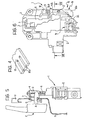
- This device includes a support casing 2 for fixing to the structure S ( Figure 1) of a domestic electrical appliance, near a loading or access opening O of the machine, which has an associated door P having a hook member A.
- the structure S of the machine Adjacent the opening O, the structure S of the machine has an aperture Q (Figure 1) for the passage and engagement of the hook member A when the door P is closed ( Figure 5).
- the aperture Q is big enough to allow the member A to be inserted and also to be rotated so as to be disengaged when the door P is opened ( Figure 12).
- the casing 2 of the device 1 has an aperture 3 facing the aperture Q ( Figure 1) for inserting the hook member A.
- a retaining member or slider 4 is slidably mounted inside the casing 2 of the device, with an aperture or window 5 corresponding substantially with the aperture 3 of the casing.
- the window 5 is engageable by the end of the hook element A when the door P is closed ( Figure 5).
- a spring 6 (Figure 3) is associated with the slider 4 in a manner known per se and tends to urge it into the position shown in Figures 1 and 2.
- an electromechanical control device 7 of a known type, is arranged inside the casing 2.
- This device 7 includes a bimetal strip 8, of configuration known per se, with one end securely fixed to the support casing 2 at 9. The other end of the bimetal strip bears a contact 10 facing a contact member 11 fixed to the casing 2.
- a resistive heating element 12 such as a positive-temperature coefficient (PTC) resistor, is associated with the bimetal strip 8 in a known manner.
- PTC positive-temperature coefficient
- the bimetal strip 8 assumes the configuration shown in Figure 3, in which it keeps the movable Contact 10 separate from the fixed contact 11 and the locking element 13 is in a rest position, withdrawn inside the casing 2.
- the bimetal strip 8 changes configuration, carrying the movable contact 10 into engagement with the contact 11 and tending to push the locking member 13 into an obstruction position in which it partially protrudes out of the casing 2 so as to cooperate functionally with the retaining slider 4 in a way which will be explained in detail later.
- the retaining slider 4 is mounted for movement relative to the support casing 2 between a rest position, shown in Figures 1, 2 and 12, 13, in which it allows the hook member A to engage the window 5 when the door P is closed and to disengage therefrom when the door is opened.
- the retaining slider 4 has a lateral projection 4a.
- the projection 4a contacts the end of the locking member 13.
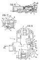
- the retaining slider 4 is movable into a working position, shown in figures 5 and 6, in which is holds the hook member A in the condition closing the door P. In this position, the projection 4a of the slider 4 uncovers the locking member 13, as shown most clearly in Figure 6, enabling it to move into the projecting position under the control of the bimetal strip 8, when this latter is heated by the resistor 1 ( Figures 9 to 11).
- An unlocking device associated with the locking device 13, is generally indicated 15 in Figure 2.
- the unlocking device 15 includes a rocker 16 pivoted at 17 on the support casing about an axis substantially parallel to the direction of movement of the locking member 13.
- the rocker 16 has an arm 16a extending near the path of the locking member 13 and an opposite arm 16b.
- the end of the arm 16a of the rocker 16 extends beneath a resilient flap 18 fixed to the support casing.
- this flap (see Figure 4 in particular) has a plurality of slits 18a giving it the substantial appearance of a comb.
- the end of the arm 16a thereof slides against the flap 18 which offers some frictional resistance.
- the flap 18, which presses on the end of the said arm of the rocker, also helps to ensure that the rocker pivots only about the pivotal axis 17.
- an electrically-controlled actuator 19 is arranged in the casing 2 near the end of the arm 16b of the rocker 16.
- this actuator includes a solenoid 20 with a movable member 21, constituted at least in part of ferromagnetic material, mounted therein.
- the movable member 21 has a terminal pin 22 extending near to the end of the arm 16b of the rocker 16.
- the movable member 21-22 of the actuator device 19 is in the position shown in Figure 2 and the rocker 16 is positioned whereby the end of the arm 16a does not interfere with the path of movement of the locking device 13.
- the position of the rocker 16 is stabilised by the resilient flap 18.
- the top of the locking member 13 is bevelled to form an inclined plane 13a.
- the end of the arm 16a of the rocker 16 is correspondingly bevelled underneath to form an inclined plane 16c.
- the movable contact 10 carried by the strip 8 and the fixed contact 11 constitute together a switch arranged in series in an electric line supplying the domestic electrical appliance.
- the solenoid 20 of the actuator 19 can be connected to this electric line, downstream of the switch constituted by the contacts 10 and 11.
- a control unit (not illustrated) thereof causes current to flow to the resistor 12, thereby heating and commutating the bimetal strip 8 which thus changes to the configuration shown in Figure 7.
- the movable contact 10 is made to engage the fixed contact 11 and the locking member 13 is moved into its partially projecting position in which it prevents the slider 4 from resuming its rest position of Figure 1, by blocking the path of the projection 4a of the said slider 4. In this condition, the door P cannot be opened.
- the movable core 21-22 moves into the position shown in Figure 9, causing the rocker 16 to rotate.
- the end of the arm 16a of the rocker 16 engages the inclined plane 13a of the locking member 13 with its own inclined plane 16a, causing the locking member to return to its withdrawn position ( Figures 10 and 11).
- the solenoid 20 of the actuator device 19 can be activated by a control impulse from the control unit of the domestic appliance, as a result of the user pressing a control button to open the door P.
- the control unit only activates the said solenoid if the safety conditions for allowing the door P to be opened are fulfilled at that moment.
- the projection 4a of the slider 4 partially overlaps the locking member 13 before this latter is disengaged by the arm 16a of the rocker 16, whereby the slider 4 is able to continue on its path until it reaches its rest position ( Figures 12 to 14). Once it has reached this condition, the hook member A of the door P can be disengaged from the retaining slider 4, and the window Q, and the door P can be opened.
- the door P can be unlocked and opened during operation extremely quickly, without any annoying waiting time.
Landscapes
- Engineering & Computer Science (AREA)
- Textile Engineering (AREA)
- Main Body Construction Of Washing Machines And Laundry Dryers (AREA)
- Control Of Vending Devices And Auxiliary Devices For Vending Devices (AREA)
- Lock And Its Accessories (AREA)
- Electric Ovens (AREA)
Claims (9)
- Dispositif (1) de fermeture de porte (P) pour appareil électroménager, comprenant :caractérisé en ce qu'il comprend aussi un dispositif de déverrouillage (15) qui comprendun boítier support (2)un coulisseau de retenue (4) monté dans le boítier (2) pour se déplacer entre une position de travail dans laquelle il maintient un organe d'accrochage (A) fixé à la porte (P), et une position de repos dans laquelle il permet audit organe d'accrochage (A) de se désengager de façon à permettre l'ouverture de la porte, etun dispositif de commande électromécanique (7) qui comprend un bilame (8) associé à un élément de chauffage résistif (12) et qui est couplé avec un dispositif mobile de verrouillage (13), dont le déplacement est le résultat de l'échauffement dudit bilame (8), depuis une position de repos ou de relâche jusqu'à une position de blocage dans laquelle il empêche le coulisseau de retenue (4) de se déplacer de sa position de travail à sa position de repos ;
un organe de commande (16) monté dans le boítier (2) pour se déplacer entre une position de repos dans laquelle il permet au dit organe de verrouillage (13) de se déplacer et une position de travail dans laquelle il agit pour forcer ledit organe de verrouillage (13) à se déplacer depuis sa position de blocage à sa position de relâche, et
un vérin commandé électriquement(19) associé avec ledit dispositif de déverrouillage (15) qui peut être actionné pour obliger ce dernier à se déplacer depuis sa position de travail à sa position de repos. - Dispositif de fermeture selon la revendication 1, caractérisé en ce que ledit organe de commande (16) est un basculeur (16) monté en pivot sur ledit boítier support (2) autour d'un axe (17) substantiellement parallèle à la direction de déplacement dudit organe de verrouillage (13).
- Dispositif de fermeture selon la revendication 2, caractérisé en ce qu'un bras (16a) dudit basculeur (16) agit pour s'interposer avec l'organe de verrouillage (13) quand ce dernier est dans sa position de blocage, et de fonctionner en commun avec ledit coulisseau de retenue (4, 4a) de telle sorte que ledit basculeur (16) puisse être repoussé vers sa position de repos comme résultat du déplacement dudit coulisseau (4) vers sa position de repos, suivant l'activation du dispositif de déverrouillage (15).
- Dispositif de fermeture selon la revendication 3, caractérisé en ce qu'un organe de friction (18) est associé avec ledit bras (16a) du basculeur (16) pour en contrer l'oscillation.
- Dispositif de fermeture selon la revendication 4, caractérisé en ce ledit organe de friction est un volet élastique (18) fixé au boítier support (2) de telle sorte que ledit bras (16a) du basculeur (16) glisse contre lui.
- Dispositif de fermeture selon la revendication 5, caractérisé en ce que ledit volet élastique (18) a une pluralité de fentes (18a) lui donnant substantiellement l'apparence d'un peigne.
- Dispositif de fermeture selon l'une quelconque des précédentes revendications, caractérisé en ce que des surfaces communes de l'organe de verrouillage (13) et de l'organe de commande (16) ont des plans respectifs (13a ; 16c) inclinés par rapport au plan de déplacement dudit organe de commande (16).
- Dispositif de fermeture selon l'une quelconque des précédentes revendications, caractérisé en ce que ledit vérin (19) comprend un solénoïde (20) avec un organe mobile associé (21, 22) pour pouvoir fonctionner en commun avec ledit organe de commande (16) du dispositif de déverrouillage (15).
- Dispositif de fermeture selon la revendication 8 dans laquelle un contact mobile (10) est associé avec ledit bilame (8) pour pouvoir fonctionner en commun avec un contact (11) fixé au boítier (2) pour fermer une ligne d'alimentation électrique seulement lorsque l'organe de verrouillage (13) est dans sa dite position de blocage ;
caractérisé en ce que ledit solénoïde (20) est branché sur ladite ligne d'alimentation en aval desdits contacts (10, 11).
Applications Claiming Priority (2)
| Application Number | Priority Date | Filing Date | Title |
|---|---|---|---|
| ITTO980511 | 1998-06-11 | ||
| IT98TO000511A ITTO980511A1 (it) | 1998-06-11 | 1998-06-11 | Dispositivo di bloccaggio di un portello di un apparecchio elettrodome stico. |
Publications (2)
| Publication Number | Publication Date |
|---|---|
| EP0965677A1 EP0965677A1 (fr) | 1999-12-22 |
| EP0965677B1 true EP0965677B1 (fr) | 2003-04-09 |
Family
ID=11416840
Family Applications (1)
| Application Number | Title | Priority Date | Filing Date |
|---|---|---|---|
| EP99111297A Expired - Lifetime EP0965677B1 (fr) | 1998-06-11 | 1999-06-10 | Dispositif de fermeture de porte pour un appareil électro-ménager |
Country Status (3)
| Country | Link |
|---|---|
| EP (1) | EP0965677B1 (fr) |
| DE (1) | DE69906623T2 (fr) |
| IT (1) | ITTO980511A1 (fr) |
Families Citing this family (14)
| Publication number | Priority date | Publication date | Assignee | Title |
|---|---|---|---|---|
| IT1320477B1 (it) * | 2000-06-30 | 2003-11-26 | Bitron Spa | Dispositivo blocca-porta, particolarmente per un apparecchioelettrodomestico. |
| DE10038376C2 (de) | 2000-08-07 | 2003-04-30 | Zangenstein Elektro | Türverriegelung für die Tür eines elektrischen Haushaltsgerätes |
| EP1217117B1 (fr) | 2000-12-22 | 2005-03-02 | Elektromanufaktur Zangenstein, Hanauer GmbH & Co. KGaA | Dispositif pour verrouiller et déverrouiller une serrure de porte d'un appareil électrique |
| ITTO20030273A1 (it) * | 2003-04-09 | 2004-10-10 | Bitron Spa | Dispositivo di bloccaggio e sbloccaggio del portello |
| ITTO20031021A1 (it) * | 2003-12-18 | 2005-06-19 | Bitron Spa | Dispositivo blocca-porta a sicurezza incrementata, particolarmente per apparecchi elettrodomestici. |
| WO2006004317A1 (fr) * | 2004-05-20 | 2006-01-12 | Lg Electronics Inc. | Commutateur de verrouillage de porte de machine a laver et son procede |
| ES2277231T3 (es) * | 2004-07-13 | 2007-07-01 | C.R.F. Societa Consortile Per Azioni | Aparato electrodomestico, en particular, maquina para lavar y/o secar un dispositivo de enclavamiento/liberacion de la puerta que se puede accionar electricamente. |
| ITTO20050473A1 (it) * | 2005-07-08 | 2007-01-09 | Bitron Spa | Dispositivo di ritenuta, particolarmente per una porta di un apparecchio elettrodomestico |
| ITTO20070295A1 (it) * | 2007-05-03 | 2008-11-04 | Bitron Spa | Sistema blocca-porta per un apparecchio elettrodomestico |
| DE602008006516D1 (de) * | 2008-02-18 | 2011-06-09 | Electrolux Home Prod Corp | Türverschlussvorrichtung mit Wärmeschutz und Wärmeschutzverfahren für eine Türverschlussvorrichtung in einer Haushaltsvorrichtung |
| DE102008030902A1 (de) * | 2008-06-30 | 2009-12-31 | BSH Bosch und Siemens Hausgeräte GmbH | Türverschließvorrichtung für ein Hausgerät, Türanordnung mit einer Türverschließvorrichtung und Verfahren zum Verschließen einer Tür eines Hausgeräts |
| IT1400623B1 (it) | 2010-06-18 | 2013-06-14 | Eltek Spa | Dispositivo blocco porta per elettrodomestici con attuatore termico. |
| ITTO20110569A1 (it) * | 2011-06-29 | 2012-12-30 | Bitron Spa | Dispositivo di bloccaggio e sbloccaggio del portello di un apparecchio elettrodomestico |
| DE102012203484A1 (de) * | 2012-03-06 | 2013-09-12 | BSH Bosch und Siemens Hausgeräte GmbH | Haushaltsgerät |
Citations (1)
| Publication number | Priority date | Publication date | Assignee | Title |
|---|---|---|---|---|
| DE2708086A1 (de) * | 1976-03-18 | 1977-09-22 | Texas Instruments Italia Spa | Tuerblockierungsvorrichtung |
Family Cites Families (4)
| Publication number | Priority date | Publication date | Assignee | Title |
|---|---|---|---|---|
| IT1162081B (it) * | 1978-02-24 | 1987-03-18 | Omp Off Meccano Plast | Dispositivo di bloccaggio della porta,in particolare per lavabiancheria domestiche e simili |
| DE3430414A1 (de) * | 1984-08-18 | 1986-02-27 | Ellenberger & Poensgen Gmbh, 8503 Altdorf | Tuerverriegelungsvorrichtung mit sofortverriegelung und verzoegerter entriegelung mit wasserstandsueberwachung |
| SE461989B (sv) * | 1988-09-16 | 1990-04-23 | Electrolux Ab | Laasanordning foer en lucka till en tvaettmaskin, centrifug e d |
| IT1250393B (it) * | 1991-06-13 | 1995-04-07 | Zanussi Elettrodomestici | Dispositivo di bloccaggio della porta per macchine lavatrici o asciugatrici di biancheria. |
-
1998
- 1998-06-11 IT IT98TO000511A patent/ITTO980511A1/it unknown
-
1999
- 1999-06-10 DE DE69906623T patent/DE69906623T2/de not_active Expired - Fee Related
- 1999-06-10 EP EP99111297A patent/EP0965677B1/fr not_active Expired - Lifetime
Patent Citations (1)
| Publication number | Priority date | Publication date | Assignee | Title |
|---|---|---|---|---|
| DE2708086A1 (de) * | 1976-03-18 | 1977-09-22 | Texas Instruments Italia Spa | Tuerblockierungsvorrichtung |
Also Published As
| Publication number | Publication date |
|---|---|
| ITTO980511A1 (it) | 1999-12-13 |
| DE69906623D1 (de) | 2003-05-15 |
| EP0965677A1 (fr) | 1999-12-22 |
| DE69906623T2 (de) | 2004-02-12 |
Similar Documents
| Publication | Publication Date | Title |
|---|---|---|
| KR100681570B1 (ko) | 제품의 도어 래치내의 메모리 금속 액추에이터 | |
| EP0965677A1 (fr) | Dispositif de fermeture de porte pour un appareil électro-ménager | |
| CN100595368C (zh) | 具有可电气致动的门锁闭/松释装置的机器的家用电器 | |
| US6634684B2 (en) | Latching mechanism for the door of an electric household appliance | |
| CN109252765B (zh) | 具有锁定机构的上拉限位门闩锁 | |
| US6886868B2 (en) | Door-locking assembly | |
| US4623179A (en) | Door latch for appliance | |
| US7775070B2 (en) | Door power interruption safety switch of washing machine and method of operation thereof | |
| EP2148951B1 (fr) | Loquet avec déverrouillage en cas de coupure de courant | |
| KR100923146B1 (ko) | 가전 제품 도어를 위한 도어 잠금 장치 | |
| US6840553B2 (en) | Apparatus for blocking and releasing a door lock of an electrical appliance | |
| CN111910397A (zh) | 用于家用电器的门锁 | |
| JPH02502256A (ja) | 洗浄機械用ドアラッチ | |
| CA1235780A (fr) | Systeme de verrouillage-deverrouillage sur porte d'appareil menager | |
| WO2016177574A1 (fr) | Dispositif de verrouillage pour porte d'appareil ménager | |
| EP2564000B1 (fr) | Loquet pour appareil avec retenue améliorée de la porte à des températures élevées | |
| EP1640493B1 (fr) | Verrouillage de porte pour appareil ménager | |
| EP0518147B1 (fr) | Dispositif de verrouillage de porte pour machines à laver et/ou sécher le linge | |
| EP0439849B1 (fr) | Dispositif de verrouillage de porte avec verrouillage rapide et déverrouillage retardé, notamment d'une machine à laver | |
| CA1047628A (fr) | Mecanisme de verrouillage commande par moteur | |
| GB2031053A (en) | Improvements in or Relating to Interlock Mechanism | |
| EP1861535B1 (fr) | Dispositif de blocage pour la porte d'un appareil menager electrique, en particulier la porte d'une machine a laver | |
| GB2162240A (en) | Delayed-release door lock | |
| GB2047966A (en) | Washing machine with safety device | |
| GB2196689A (en) | Delayed-release door lock |
Legal Events
| Date | Code | Title | Description |
|---|---|---|---|
| PUAI | Public reference made under article 153(3) epc to a published international application that has entered the european phase |
Free format text: ORIGINAL CODE: 0009012 |
|
| AK | Designated contracting states |
Kind code of ref document: A1 Designated state(s): DE ES FR GB |
|
| AX | Request for extension of the european patent |
Free format text: AL;LT;LV;MK;RO;SI |
|
| 17P | Request for examination filed |
Effective date: 20000608 |
|
| AKX | Designation fees paid |
Free format text: DE ES FR GB |
|
| GRAH | Despatch of communication of intention to grant a patent |
Free format text: ORIGINAL CODE: EPIDOS IGRA |
|
| GRAH | Despatch of communication of intention to grant a patent |
Free format text: ORIGINAL CODE: EPIDOS IGRA |
|
| GRAA | (expected) grant |
Free format text: ORIGINAL CODE: 0009210 |
|
| AK | Designated contracting states |
Designated state(s): DE ES FR GB |
|
| PG25 | Lapsed in a contracting state [announced via postgrant information from national office to epo] |
Ref country code: FR Free format text: LAPSE BECAUSE OF FAILURE TO SUBMIT A TRANSLATION OF THE DESCRIPTION OR TO PAY THE FEE WITHIN THE PRESCRIBED TIME-LIMIT Effective date: 20030409 |
|
| REG | Reference to a national code |
Ref country code: GB Ref legal event code: FG4D |
|
| PG25 | Lapsed in a contracting state [announced via postgrant information from national office to epo] |
Ref country code: ES Free format text: LAPSE BECAUSE OF FAILURE TO SUBMIT A TRANSLATION OF THE DESCRIPTION OR TO PAY THE FEE WITHIN THE PRESCRIBED TIME-LIMIT Effective date: 20031030 |
|
| PLBE | No opposition filed within time limit |
Free format text: ORIGINAL CODE: 0009261 |
|
| STAA | Information on the status of an ep patent application or granted ep patent |
Free format text: STATUS: NO OPPOSITION FILED WITHIN TIME LIMIT |
|
| EN | Fr: translation not filed | ||
| 26N | No opposition filed |
Effective date: 20040112 |
|
| PGFP | Annual fee paid to national office [announced via postgrant information from national office to epo] |
Ref country code: GB Payment date: 20050516 Year of fee payment: 7 |
|
| PGFP | Annual fee paid to national office [announced via postgrant information from national office to epo] |
Ref country code: DE Payment date: 20050520 Year of fee payment: 7 |
|
| PG25 | Lapsed in a contracting state [announced via postgrant information from national office to epo] |
Ref country code: GB Free format text: LAPSE BECAUSE OF NON-PAYMENT OF DUE FEES Effective date: 20060610 |
|
| PG25 | Lapsed in a contracting state [announced via postgrant information from national office to epo] |
Ref country code: DE Free format text: LAPSE BECAUSE OF NON-PAYMENT OF DUE FEES Effective date: 20070103 |
|
| GBPC | Gb: european patent ceased through non-payment of renewal fee |
Effective date: 20060610 |