EP0965708A2 - Dispositif de commande par bouton-poussoir d'une serrure de véhicule - Google Patents
Dispositif de commande par bouton-poussoir d'une serrure de véhicule Download PDFInfo
- Publication number
- EP0965708A2 EP0965708A2 EP99111640A EP99111640A EP0965708A2 EP 0965708 A2 EP0965708 A2 EP 0965708A2 EP 99111640 A EP99111640 A EP 99111640A EP 99111640 A EP99111640 A EP 99111640A EP 0965708 A2 EP0965708 A2 EP 0965708A2
- Authority
- EP
- European Patent Office
- Prior art keywords
- key cylinder
- respect
- axis
- slide member
- angular
- Prior art date
- Legal status (The legal status is an assumption and is not a legal conclusion. Google has not performed a legal analysis and makes no representation as to the accuracy of the status listed.)
- Withdrawn
Links
Images

Classifications
-
- E—FIXED CONSTRUCTIONS
- E05—LOCKS; KEYS; WINDOW OR DOOR FITTINGS; SAFES
- E05B—LOCKS; ACCESSORIES THEREFOR; HANDCUFFS
- E05B13/00—Devices preventing the key or the handle or both from being used
- E05B13/10—Devices preventing the key or the handle or both from being used formed by a lock arranged in the handle
- E05B13/105—Devices preventing the key or the handle or both from being used formed by a lock arranged in the handle the handle being a pushbutton
-
- E—FIXED CONSTRUCTIONS
- E05—LOCKS; KEYS; WINDOW OR DOOR FITTINGS; SAFES
- E05B—LOCKS; ACCESSORIES THEREFOR; HANDCUFFS
- E05B13/00—Devices preventing the key or the handle or both from being used
- E05B13/10—Devices preventing the key or the handle or both from being used formed by a lock arranged in the handle
- E05B13/101—Devices preventing the key or the handle or both from being used formed by a lock arranged in the handle for disconnecting the handle
-
- E—FIXED CONSTRUCTIONS
- E05—LOCKS; KEYS; WINDOW OR DOOR FITTINGS; SAFES
- E05B—LOCKS; ACCESSORIES THEREFOR; HANDCUFFS
- E05B77/00—Vehicle locks characterised by special functions or purposes
Definitions
- the present invention relates to a push-button actuating device for controlling a vehicle lock.
- the present invention relates to a push-button actuating device of the type comprising a key cylinder for switching a security member of the lock; and a control push-button by which to open the lock.
- the key cylinder of known actuating devices of the above type must rotate "idly" in the event the key cylinder is rotated using other than the cylinder-dedicated key, and in the event the dedicated key is not inserted properly.
- a push-button actuating device for a vehicle lock, the device comprising a supporting body having a respective axis; a key cylinder movable with respect to the supporting body along said axis; a dedicated key by which to rotate the key cylinder about said axis with respect to said supporting body; a control member connectable to said lock and which slides axially with respect to said supporting body; and connecting means for connecting said key cylinder to said control member; characterized in that said connecting means comprise releasable first angular-constraint means; elastic means for maintaining said first angular-constraint means in a first operating position making said key cylinder and said control member angularly integral with each other; and cam actuating means acting on said first angular-constraint means to move the first angular-constraint means into a second operating position in which the key cylinder is free to rotate with respect to said control member and said supporting body; releasable second angular-constraint means
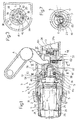
- Number 1 in Figures 1 and 2 indicates as a whole a handle for a vehicle door (not shown).
- Handle 1 comprises a grip body 2; and a push-button actuating device 3 for controlling a lock (not shown) on the door.
- device 3 comprises an outer tubular supporting body 5 having a respective axis 6 and connectable integrally to a structure of the door and to grip body 2 at an opening 7 formed in grip body 2, coaxially with axis 6, to enable the inside of body 5 to communicate with the outside.
- a further tubular body 8 extends, coaxially with axis 6, through opening 7 and partly inside body 5, and has an end portion 9 projecting outwards of grip body 2, and an opposite end portion 10 engaging an end collar portion 11 of a slide member 12 inside body 5 and coaxial with axis 6.
- slide member 12 is defined by a further elongated tubular body and is connected to body 8 by a pin 13, which extends perpendicularly to axis 6 through collar portion 11 and partly inside an outer circumferential groove 15 on portion 10 to connect body 8 in rotary manner about axis 6 and in axially-fixed manner to member 12.
- slide member 12 has an end portion 16, opposite collar portion 11, which is connected in axially-sliding, angularly-fixed manner to tubular body 5 by means of a splined coupling 17 ( Figures 2, 6 and 7).
- Body 8 and member 12 define a chamber housing, in line with each other and coaxial with axis 6, a known key cylinder 20 having a respective dedicated key 21, and an end portion 22 of a control member 23, and form part of a connecting assembly 19 for connecting key cylinder 20 to member 23.
- Member 23 comprises an end portion 24, opposite portion 22, which defines an axial shoulder 24a ( Figures 1 and 2), against which member 12 rests, and is connected in known manner to a security member (not shown) and to a lock-opening lever A.
- key cylinder 20 engages tubular body 8 in rotary manner about axis 6 to define a push-button of device 3, comprises a head 25 resting against an inner axial shoulder 26 of body 8, and is locked axially with respect to body 8 by an ⁇ -shaped spring 27 ( Figures 2 and 4) engaging an outer circumferential groove 28 formed on body 8 and adjacent to portion 10, and a corresponding circumferential groove 29 formed on an intermediate portion of key cylinder 20.
- the intermediate portion of key cylinder 20 houses a number of known rocker-arm members 31 - only one shown schematically in Figure 1 - which are maintained inside key cylinder 20 by key 21, but which, when key 21 is partly or fully withdrawn, project radially outwards of the intermediate portion through respective openings (not shown) and engage respective axial grooves 32 ( Figure 1) inside body 8 to angularly and releasably connect key cylinder 20 and body 8.
- slide member 12 houses a slide body 35 which forms part of assembly 19, surrounds an end portion 36, opposite head 25, of key cylinder 20 coaxially with axis 6, and is maintained in a first operating position (Figure 1) resting against an axial shoulder on slide member 12 by a spring 37 surrounding portion 36 and compressed between body 35 and a radial surface of key cylinder 20 ( Figure 2).
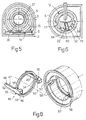
- slide body 35 is connected to control member 23 in axially-sliding, angularly-fixed manner by two appendixes or axial arms 38 facing each other, integral with control member 23, and engaging in sliding manner respective diametrically-opposite axial seats 39 formed on slide body 35 ( Figure 3).
- slide body 35 is also connected in angularly-fixed manner to key cylinder 20 by a splined coupling forming part of assembly 19 and comprising two radial teeth 41 integral with portion 36 of key cylinder 20 and engaging, positively and in axially-sliding manner, respective seats 42 formed in slide body 35.
- slide body 35 is movable axially into a second operating position ( Figure 2) in which teeth 41 release seats 42 to enable key cylinder 20 to be rotated freely with respect to slide body 35 and control member 23 by a cam device 44 ( Figure 8) forming part of assembly 19.
- device 44 comprises, in addition to member 12, a further slide body 45 which surrounds spring 37, coaxially with axis 6, and in turn comprises an intermediate annular portion 46 resting against a front surface of slide body 35, and two opposite fork-shaped end portions 47 and 48.
- Portion 47 comprises two diametrically-opposite axial arms 49, each of which engages, in sliding manner and with substantially no circumferential clearance, a respective axial slide seat 50 formed through end portion 10 of tubular body 8; and portion 48 comprises two axial teeth 52, each of which forms an extension of a respective arm 49 and is connected in rotary manner about axis 6 and in axially-fixed manner to slide body 35 by a respective inner radial projection 53 engaging an outer circumferential groove 54 formed on body 35.
- each tooth 52 is defined laterally by two opposite flat surfaces 55 converging with each other towards a free end of respective tooth 52.
- teeth 52 engage respective complementary flared axial seats 57 formed on slide member 12, on opposite sides of axis 6, and each defined by two flat surfaces 58 converging with each other towards the bottom of respective seat 57.
- Surfaces 58 each extend parallel to a respective surface 55, and, when slide body 35 is in the first position, are each positioned contacting respective surface 55 to define respective inclined-plane assemblies 60 ( Figures 2) for overcoming the action of spring 37 and sliding body 35 axially towards tubular body 8 regardless of the rotation direction of body 8 about axis 6.
- control member 23 is fitted with a radial pin 62 which projects outwards of member 12 and engages a circumferential seat 63 formed on member 12 and defined by two radial shoulders 64 ( Figure 6) defining respective limit angular positions of pin 62.
- pin 62 and, consequently, control member 23 are maintained in a zero relative angular position between the limit angular positions by a torsion pin spring 65.
- device 3 Operation of device 3 will now be described as of the condition shown in Figure 1, in which slide body 35 is set by spring 37 to the first operating position and is therefore connected angularly integral with key cylinder 20, and in which dedicated key 21 is withdrawn from key cylinder 20 so that rocker-arm members 31 project outwards of key cylinder 20 and engage respective grooves 32 to angularly connect key cylinder 20 and tubular body 8.
- rocker-arm members 31 When dedicated key 21 is inserted inside key cylinder 20, as of the above condition, rocker-arm members 31 are withdrawn fully inside key cylinder 20 to enable key cylinder 20 to rotate freely with respect to body 8 and so switch the security member (not shown) of the lock by rotating body 35 which in turn rotates control member 23.
- body 8 When axial pressure is exerted on key cylinder 20, body 8, slide member 12 and control member 23 are moved forward simultaneously, and control member 23 opens the lock.
- the characteristics of device 3 as described therefore provide for preventing forcible entry, by key cylinder 20, in the absence of dedicated key 21, continually rotating "idly” or clicking about axis 6 and producing no rotation of control member 23, so that the lock remains disabled and cannot be opened even by axial pressure on key cylinder 20 and/or body 8.
- Device 3 as described is therefore also extremely straightforward construction-wise, comprises a relatively small number of fairly straightforward components, and is therefore relatively cheap to produce and assemble.
Landscapes
- Lock And Its Accessories (AREA)
Applications Claiming Priority (2)
| Application Number | Priority Date | Filing Date | Title |
|---|---|---|---|
| IT98TO000531A ITTO980531A1 (it) | 1998-06-19 | 1998-06-19 | Dispositivo di azionamento a pulsante per una serratura di un veicolo. |
| ITTO980531 | 1998-06-19 |
Publications (2)
| Publication Number | Publication Date |
|---|---|
| EP0965708A2 true EP0965708A2 (fr) | 1999-12-22 |
| EP0965708A3 EP0965708A3 (fr) | 2000-10-18 |
Family
ID=11416858
Family Applications (1)
| Application Number | Title | Priority Date | Filing Date |
|---|---|---|---|
| EP99111640A Withdrawn EP0965708A3 (fr) | 1998-06-19 | 1999-06-16 | Dispositif de commande par bouton-poussoir d'une serrure de véhicule |
Country Status (2)
| Country | Link |
|---|---|
| EP (1) | EP0965708A3 (fr) |
| IT (1) | ITTO980531A1 (fr) |
Family Cites Families (1)
| Publication number | Priority date | Publication date | Assignee | Title |
|---|---|---|---|---|
| DE4408910A1 (de) * | 1994-03-16 | 1995-09-21 | Huelsbeck & Fuerst | Verschlußvorrichtung mit einem zugleich als Druckhandhabe zum Betätigen von Schloßgliedern dienenden Schließzylinder |
-
1998
- 1998-06-19 IT IT98TO000531A patent/ITTO980531A1/it unknown
-
1999
- 1999-06-16 EP EP99111640A patent/EP0965708A3/fr not_active Withdrawn
Also Published As
| Publication number | Publication date |
|---|---|
| EP0965708A3 (fr) | 2000-10-18 |
| ITTO980531A1 (it) | 1999-12-19 |
Similar Documents
| Publication | Publication Date | Title |
|---|---|---|
| US6523382B1 (en) | Free wheeling lock assembly | |
| KR890005209B1 (ko) | 프리 노브 로테이션과 프런트 엔드 로딩을 포함하는 문자물쇠용 노브 조립체 | |
| CA2917486C (fr) | Mecanisme de verrou a liberation de sortie | |
| US9982455B2 (en) | Side mounted privacy lock for a residential door | |
| AU747009B2 (en) | Closing device for closing functions in vehicles in particular | |
| US6174005B1 (en) | Bi-directional handle and latch assembly | |
| CN107859443B (zh) | 车辆用门锁装置 | |
| US5050410A (en) | Locking device for motor vehicles with sleeve-actuated switch | |
| CZ298262B6 (cs) | Okenní a/nebo dverní kování | |
| JPH0557391B2 (fr) | ||
| US11851911B2 (en) | Pushbutton mechanisms for locksets | |
| US20150303620A1 (en) | Locking mechanism for plug-in connectors | |
| KR20020000646A (ko) | 도어 록킹 장치 | |
| US9376843B2 (en) | Position holding device for rotating lever and vehicle door lock device provided with said position holding device for rotating lever | |
| JP4955579B2 (ja) | 自動車のロッキングシステムのための解放自在なロック | |
| TWI225117B (en) | A lock | |
| CA2444516C (fr) | Poignee exterieure de deverrouillage | |
| JP7000736B2 (ja) | 車両用ハンドル装置 | |
| JP4842284B2 (ja) | 自動車のロッキングシステムのための解放自在なロック | |
| AU734168B2 (en) | Closing device with a key operable closing cylinder which simultaneously serves as a hand operated pushing device for operating locking elements | |
| US7997109B2 (en) | Disengageable lock for motor vehicle locking system | |
| US3819214A (en) | Cylindrical lock set | |
| KR100862571B1 (ko) | 잼현상 해소구조를 가진 차량용 도어 잠금장치 | |
| CN222184399U (zh) | 一种按钮解锁的门窗把手 | |
| JP3759690B2 (ja) | 車両ドアロック装置のダブルレバー組付構造 |
Legal Events
| Date | Code | Title | Description |
|---|---|---|---|
| PUAI | Public reference made under article 153(3) epc to a published international application that has entered the european phase |
Free format text: ORIGINAL CODE: 0009012 |
|
| AK | Designated contracting states |
Kind code of ref document: A2 Designated state(s): DE ES FR GB |
|
| AX | Request for extension of the european patent |
Free format text: AL;LT;LV;MK;RO;SI |
|
| PUAL | Search report despatched |
Free format text: ORIGINAL CODE: 0009013 |
|
| AK | Designated contracting states |
Kind code of ref document: A3 Designated state(s): AT BE CH CY DE DK ES FI FR GB GR IE IT LI LU MC NL PT SE |
|
| AX | Request for extension of the european patent |
Free format text: AL;LT;LV;MK;RO;SI |
|
| 17P | Request for examination filed |
Effective date: 20001106 |
|
| AKX | Designation fees paid |
Free format text: DE ES FR GB |
|
| 17Q | First examination report despatched |
Effective date: 20040812 |
|
| STAA | Information on the status of an ep patent application or granted ep patent |
Free format text: STATUS: THE APPLICATION IS DEEMED TO BE WITHDRAWN |
|
| 18D | Application deemed to be withdrawn |
Effective date: 20050223 |