EP0965722A1 - Rolladen für Tür, Fenster oder dergleichen - Google Patents
Rolladen für Tür, Fenster oder dergleichen Download PDFInfo
- Publication number
- EP0965722A1 EP0965722A1 EP98440135A EP98440135A EP0965722A1 EP 0965722 A1 EP0965722 A1 EP 0965722A1 EP 98440135 A EP98440135 A EP 98440135A EP 98440135 A EP98440135 A EP 98440135A EP 0965722 A1 EP0965722 A1 EP 0965722A1
- Authority
- EP
- European Patent Office
- Prior art keywords
- slot
- winding shaft
- under
- roller shutter
- blade
- Prior art date
- Legal status (The legal status is an assumption and is not a legal conclusion. Google has not performed a legal analysis and makes no representation as to the accuracy of the status listed.)
- Ceased
Links
- 238000004804 winding Methods 0.000 claims description 48
- 230000005540 biological transmission Effects 0.000 claims description 26
- 230000000694 effects Effects 0.000 claims description 9
- 210000002268 wool Anatomy 0.000 claims description 7
- 241000722921 Tulipa gesneriana Species 0.000 claims description 3
- 230000001846 repelling effect Effects 0.000 claims description 2
- 238000005096 rolling process Methods 0.000 abstract description 7
- 230000035515 penetration Effects 0.000 description 5
- 238000007789 sealing Methods 0.000 description 5
- 238000004519 manufacturing process Methods 0.000 description 3
- 238000009792 diffusion process Methods 0.000 description 1
- 230000005484 gravity Effects 0.000 description 1
- 210000004209 hair Anatomy 0.000 description 1
- 210000000056 organ Anatomy 0.000 description 1
Images
Classifications
-
- E—FIXED CONSTRUCTIONS
- E06—DOORS, WINDOWS, SHUTTERS, OR ROLLER BLINDS IN GENERAL; LADDERS
- E06B—FIXED OR MOVABLE CLOSURES FOR OPENINGS IN BUILDINGS, VEHICLES, FENCES OR LIKE ENCLOSURES IN GENERAL, e.g. DOORS, WINDOWS, BLINDS, GATES
- E06B9/00—Screening or protective devices for wall or similar openings, with or without operating or securing mechanisms; Closures of similar construction
- E06B9/02—Shutters, movable grilles, or other safety closing devices, e.g. against burglary
- E06B9/08—Roll-type closures
- E06B9/11—Roller shutters
- E06B9/17—Parts or details of roller shutters, e.g. suspension devices, shutter boxes, wicket doors, ventilation openings
- E06B9/17076—Sealing or antirattling arrangements
Definitions
- the invention relates to a rolling shutter for a door, window or analog comprising an apron, on the one hand, capable of being rolled up around a winding shaft housed in a box and, on the other hand, likely to deploy passing through a slot in the underside of said box.
- the present invention will find its application in the field the manufacture of roller shutters intended to be installed at the level of any building.
- roller shutters meeting the description above and comprising a receiving box, internally, a winding shaft from which unrolls and on which wraps an apron constituted by a juxtaposition of the articulated ones in relation to other.
- This brush is intended to prevent the penetration of air outside inside the box.
- the hairs are designed to be in permanent contact with the apron and must have a density capable, on the one hand, of guaranteeing the tightness of the box and, on the other hand, to allow the unhindered scrolling of said apron.
- the density of the bristles of the brush then generally results of a compromise, which, in most cases, is made at detriment of the tightness of the box.
- the present invention is intended to provide a solution to the disadvantages exposed above through a shutter rolling for which air penetration is prevented at the inside of the box, ensuring its tightness directly at the level of the slot in its underside.
- the invention relates to a rolling shutter for a door, window or the like comprising an apron, on the one hand, suitable for wind around a winding shaft housed in a box and, on the other hand, likely to be deployed by passing to through a slot in the underside of said box, characterized in that in the fully extended position of the apron, it includes means designed to repel the blade, being engaged in said slot of the underside, applied against the outer longitudinal edge of this slot, under the impulse of the rotation communicated to the winding shaft whose said means are rendered united.
- said means are in the form of a wedge provided capable of being pushed back into said slot, between the edge internal longitudinal of the latter and said engaged blade in this slot, under the impulse of a transmission member connecting this corner to the winding shaft.
- said means are defined by a pad capable of coming to apply against the internal face of said wool engaged in the slot to push it against the outer longitudinal edge of the latter, this pad being secured to the lower end of a transmission whose upper end is fixed on the shaft curtain winding.
- An additional feature concerns the fact that the edge longitudinal external of the slot is provided with a seal sealing against which is able to be pushed back said blade engaged in the slot on the underside of the box.
- the means capable of pressing said wool against the edge longitudinal of the slot, in particular against the joint sealing, thus preventing the penetration of the external air inside the box.
- such means can still lock the apron in the deployed position in preventing its rise in the box under the action of a thrust exerted directly on this apron and corresponding, for example, an attempted break-in.
- such means allow, under certain conditions, to get rid of a automatic locking device in the deployed position of the apron which the skilled person knows different modes of production.
- a automatic locking device connected to the tree winding, exerts its action, generally, on the first blade of the deck whose distance is difficult to control separating it from said winding shaft.
- this action of a such locking device is rarely constant from one roller shutter to another besides, in cases individuals, it cannot fully fulfill its function of locking.
- the present invention concerns the field of roller shutter manufacturing 1 intended to equip a door, window or the like located in the level of a building.
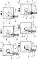
- Such a rolling shutter 1 comprises a box 2 made integral with this door, window or the like and having, in particular, an underside 3 provided with a slot 4 through which is likely to scroll an apron 5.
- This box 2 receives, internally, a winding shaft 6 on which is wound, from which takes place and to which is connected, by means of connecting means 7, said apron 5.
- This deck 5 is constituted by a juxtaposition of blades 8 interconnected by articulation means 9 and whose ends 10 engage in lateral slides 11, when deployment of said deck 5, at the outlet of the box 2, at across said slot 4.
- this rolling shutter 1 in the totally position deployed of said deck 5, comprises means 12 provided capable of push said blade 8A applied against the edge longitudinal external 13 of this slot 4 under the impulse of the rotation communicated to the winding shaft 6 whose said means 12 are made integral.
- two embodiments of the invention in which means 12 are in the form of a wedge 14 can take the form of a profile or at least one section of profile, respectively suitable, in particular after deployment of said apron 5, to extend over the entire length of the slot 4 where to be positioned, substantially, at the height of the slides side 11.
- Such a wedge 14 is provided capable of being pushed back into said slot 4, between the internal longitudinal edge 15 of the latter and said blade 8A engaged in this slot 4, and this under the impulse of a transmission member 16.
- this transmission 16 is also designed capable of pushing the corner 14 in the direction of the blade 8A of the deck 5, or even directly against the latter. Such repulsion takes place, more particularly, from the moment when said blade 8A leaves the winding shaft 6 and moves away from it during deployment of said apron 5 so that said corner 14 is positioned between the blade 8A and the internal longitudinal edge 15 of the slot 4 when entering the latter.
- said transmission member 16 is under the shape of an elastic wool 17 which, in addition to the fact that it either able to fold around the winding shaft 6 of the apron 5 during the folding of the latter, is capable of defining, in the deployed position of said deck 5, a rigid element capable of push said wedge 14 back into said slot 4 under the effect of the rotation of the winding shaft 6.
- such a transmission member 16 takes the form of one or several blades, or portions of articulated blades 18 suitable for wrap around the winding shaft 6 during folding of the apron 5.
- These articulated blades 28, during deployment or in the deployed position of said deck 5 are, themselves, brought to deploy, either by gravity or under the impetus of elastic return means 19, in particular in the form of a return spring 20, to push the wedge 14 back into the slot 4 and therefore in the direction of the blade 8A engaged therein.
- blades or portions of blades articulated 18 are able to pivot, as appropriate, one by relative to others or to the winding shaft 6 but they have a limited angle of rotation so that, once unfolded, they form a rigid element capable of push said wedge 14 back into slot 4 under the effect of rotation of the winding shaft 6.
- roller shutter 1 can, advantageously, be supplemented by guide means 21 of the corner 14 with which the latter is able to cooperate in order to be guided towards of the blade 8A when being pushed back into said slot 4 under the action of the transmission member 16.
- said wedge 14 is likely to take support in order to push back, under the pulse priced by the rotation of the winding shaft 6 and transmitted by the transmission member 16, said wool 8A in direction of the outer longitudinal edge 13 against which it comes as a squeak wall light illustrated in Figures 3 and 6.
- Such guide means 21 are constituted, so advantageous, by guiding tulips 22 of the known deck 5 by those skilled in the art, and willing, usually, to the upper end of the side slides 11 visible conne Figures 1 to 6.
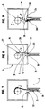
- the means 12 provided capable of pushing said blade 8A against the outer longitudinal edge 13 of slot 4 can still be defined by a shoe 24.
- the latter is able to come in applies against the internal face 25 of said blade 8A engaged in slot 4 to push it back against the longitudinal edge external 13 of the latter.
- This shoe 24 is made integral from the lower end 26 of a transmission member 16 whose upper end 27 is fixed on the shaft winding 6 of the deck 5.
- such a transmission member 16 can be in the form of one or more links articulated 28 connected to the winding shaft 6 around which they are likely to roll up when folding the deck 5 visible squeak in Figure 7.
- These links 28 are, moreover, capable of exerting a thrust on the shoe 24 to, on the one hand, push the latter back direction of the blade 8A and, on the other hand, push back this last against the outer longitudinal edge 13 of the slot 4, this under the impulse which is communicated to them by the rotation of the winding shaft 6 in the final deployment phase of the apron 5.
- the means 12 described above can advantageously be designed so as to define a apron 5 automatic locking device when this the latter is in the fully extended position.
- Such locking device is designed capable of preventing the raising, in box 2, of said apron 5, completely deployed, under the action of a thrust exerted directly on this the latter, in particular in the context of an attempted break-in.
- the rigid element defined by elastic wool 17 is likely to push back the corner 14 in the slot 4 under the effect of the rotation of the shaft 6.
- This repulsion has the effect of pressing the blade 8A against the outer longitudinal edge 13 of said slot 4 and thus ensure sealing.
- its strength is sufficient it can also prevent the ascent of the apron 5 and allow the means 12 to exercise, also, a role of automatic locking device.
- the means 12 are capable of defining, themselves, a device for automatic locking through angular limitation of the rotation of the blades 18 or the articulated links 28 of so that, after reaching a limit angle, said transmission 16 forms a rigid assembly capable of exercising, driven by the rotation of the winding shaft 6 in the direction of unfolding of the deck 5, a thrust through, as the case may be, of the corner 14 or of the pad 24, on the blade 8A. This last is then strongly pressed against the edge longitudinal external 13 of the slot 4 which allows lock the apron 5 in its deployed position, the latter being, in fact, released by traction on the organ of transmission 16 through the rotation of the shaft winding 6 in the winding direction F 'of the deck 5.
- this comprises, in combination, a device automatic locking of the deck 5 connecting the first blade from the latter to the winding shaft 6. Said device automatic locking is able to oppose the ascent of deck 5 when it is in the fully positioned position deployed, under the action of a thrust exerted on the latter.
- such a locking device automatic can then be associated with means 12 and in the form of one or more articulated blades 29 able to define, for example, connection means 7 of the type direct from the deck 5 to the winding shaft 6 and known by the skilled person.
- said deck 5 is connected to the winding shaft 6 by means of connection 7, either directly as shown in FIGS. 1 to 6, either indirectly and through the transmission member 16 as shown in Figures 7 to 9.
- connecting means 7 may, for example, be in the form of one or several attachment straps 30 as shown in Figures 4 at 9.
- the outer longitudinal edge 13 of the slot 4 can, advantageously, be provided with a seal 32 against which is able to be pushed back and come to apply said blade 8A under the action of the means 12.
- this seal 32 allows, on the one hand, to avoid, in particular at the level of the external longitudinal edge 13, the diffusion of external air towards the interior of the box 2 and thus making the latter waterproof.
- this joint 32 is preferably designed capable of presenting a coefficient significant attachment and friction on the blade 8A which, in combination with sufficient thrust on this last by means 12, advantageously makes it possible to contribute to locking the apron 5 in the fully positioned position deployed.
- the present invention not only makes it possible to respond to the sealing problems encountered in the prior art but also contributes advantageously to ensuring the locking the deployed deck and preventing it from being lifted, including breaking and entering.
Landscapes
- Engineering & Computer Science (AREA)
- Structural Engineering (AREA)
- Architecture (AREA)
- Civil Engineering (AREA)
- Operating, Guiding And Securing Of Roll- Type Closing Members (AREA)
- Refuge Islands, Traffic Blockers, Or Guard Fence (AREA)
- Storage Of Web-Like Or Filamentary Materials (AREA)
Priority Applications (4)
| Application Number | Priority Date | Filing Date | Title |
|---|---|---|---|
| EP98440135A EP0965722A1 (de) | 1998-06-18 | 1998-06-18 | Rolladen für Tür, Fenster oder dergleichen |
| DE1998601271 DE69801271T2 (de) | 1998-06-18 | 1998-10-26 | Rolladen für Tür, Fenster oder dergleichen |
| EP19980440236 EP0965723B1 (de) | 1998-06-18 | 1998-10-26 | Rolladen für Tür, Fenster oder dergleichen |
| ES98440236T ES2161512T3 (es) | 1998-06-18 | 1998-10-26 | Persiana enrollable para puerta, ventana o similar |
Applications Claiming Priority (1)
| Application Number | Priority Date | Filing Date | Title |
|---|---|---|---|
| EP98440135A EP0965722A1 (de) | 1998-06-18 | 1998-06-18 | Rolladen für Tür, Fenster oder dergleichen |
Publications (1)
| Publication Number | Publication Date |
|---|---|
| EP0965722A1 true EP0965722A1 (de) | 1999-12-22 |
Family
ID=8235689
Family Applications (1)
| Application Number | Title | Priority Date | Filing Date |
|---|---|---|---|
| EP98440135A Ceased EP0965722A1 (de) | 1998-06-18 | 1998-06-18 | Rolladen für Tür, Fenster oder dergleichen |
Country Status (3)
| Country | Link |
|---|---|
| EP (1) | EP0965722A1 (de) |
| DE (1) | DE69801271T2 (de) |
| ES (1) | ES2161512T3 (de) |
Families Citing this family (1)
| Publication number | Priority date | Publication date | Assignee | Title |
|---|---|---|---|---|
| DE102009007965B3 (de) * | 2009-02-06 | 2010-07-01 | Roma Rolladensysteme Gmbh | Gebäudeöffnungs-Verschattungsvorrichtung |
Citations (3)
| Publication number | Priority date | Publication date | Assignee | Title |
|---|---|---|---|---|
| DE3906629A1 (de) * | 1988-03-04 | 1989-11-16 | Theodor Ing Grad Rueschoff | Rolladen mit am schlitz des rolladenpanzers angeordneten abdichtungselemente |
| DE4002399A1 (de) * | 1990-01-27 | 1991-08-01 | Willi Zehe | Rolladenanlage |
| DE29502160U1 (de) * | 1995-02-10 | 1995-04-06 | Hartmann, Helmut, 36151 Burghaun | Abdichtung für einen Rolladenpanzer |
-
1998
- 1998-06-18 EP EP98440135A patent/EP0965722A1/de not_active Ceased
- 1998-10-26 DE DE1998601271 patent/DE69801271T2/de not_active Expired - Fee Related
- 1998-10-26 ES ES98440236T patent/ES2161512T3/es not_active Expired - Lifetime
Patent Citations (3)
| Publication number | Priority date | Publication date | Assignee | Title |
|---|---|---|---|---|
| DE3906629A1 (de) * | 1988-03-04 | 1989-11-16 | Theodor Ing Grad Rueschoff | Rolladen mit am schlitz des rolladenpanzers angeordneten abdichtungselemente |
| DE4002399A1 (de) * | 1990-01-27 | 1991-08-01 | Willi Zehe | Rolladenanlage |
| DE29502160U1 (de) * | 1995-02-10 | 1995-04-06 | Hartmann, Helmut, 36151 Burghaun | Abdichtung für einen Rolladenpanzer |
Also Published As
| Publication number | Publication date |
|---|---|
| ES2161512T3 (es) | 2001-12-01 |
| DE69801271D1 (de) | 2001-09-06 |
| DE69801271T2 (de) | 2002-05-02 |
Similar Documents
| Publication | Publication Date | Title |
|---|---|---|
| CA2675648C (fr) | Dispositif a rideau enroulable | |
| EP2122102B1 (de) | Vorrichtung mit flexiblem vorhang | |
| FR2970495A1 (fr) | Protection contre le soleil | |
| EP2148040B1 (de) | Behangvorrichtung insbesondere für Verdunkelungssystem und/oder Gebäudeverschlusssystem | |
| EP0818601A1 (de) | Rolladen mit dünnen lamellen, die zusammengefügt und mit geraden Kanten versehen sind | |
| FR2709322A1 (fr) | Auvent enroulable. | |
| EP0965722A1 (de) | Rolladen für Tür, Fenster oder dergleichen | |
| EP0965723B1 (de) | Rolladen für Tür, Fenster oder dergleichen | |
| FR2614929A1 (fr) | Tablier pour volet roulant | |
| CH670132A5 (de) | ||
| EP2022927B1 (de) | Verbindungsvorrichtung zwischen einer Drehwelle und dem Behang aus mit Gelenkmitteln verbundenen Lamellen eines Rollladens, die insbesondere eine Sicherheitsfunktion gegen Hochheben (von außen) gewährleistet | |
| EP1672163B1 (de) | Einrichtung zum Sichern der Rolladenstäbe eines Rolladen in ihrer seitlichen Führung | |
| EP1980704B1 (de) | Vorrichtung zur Befestigung eines Rollladenvorhangs | |
| EP2028337B1 (de) | Kupplungsvorrichtung für Jalousie, die eine Verbindung zwischen der Jalousie und der Aufrollwelle der Jalousie ermöglicht | |
| FR2875532A1 (fr) | Dispositif de deploiement et de repliement automatique d'un volet roulant | |
| FR2614928A1 (fr) | Volet roulant pour porte, fenetre et autres ouvertures | |
| EP4400688B1 (de) | Rollladenschloss und zugehörige anlage | |
| FR2765911A1 (fr) | Dispositif de blocage pour volet roulant | |
| EP2146044B1 (de) | Panzer einer Verdeckungsvorrichtung, insbesondere eines Rollladens | |
| FR2920813A1 (fr) | Tablier de volet roulant | |
| FR2888266A1 (fr) | Volet roulant pour couverture de piscine | |
| FR2761402A1 (fr) | Dispositif d'autoblocage d'un tablier de volet roulant en position deployee | |
| FR2774124A1 (fr) | Tablier de volet roulant ou similaire | |
| EP2199486A1 (de) | Planenrollo vom Typ Kastenrollo | |
| FR2487422A1 (fr) | Perfectionnements aux dispositifs de verrouillage automatique de volets roulants |
Legal Events
| Date | Code | Title | Description |
|---|---|---|---|
| GRAG | Despatch of communication of intention to grant |
Free format text: ORIGINAL CODE: EPIDOS AGRA |
|
| PUAI | Public reference made under article 153(3) epc to a published international application that has entered the european phase |
Free format text: ORIGINAL CODE: 0009012 |
|
| 17P | Request for examination filed |
Effective date: 19990322 |
|
| AK | Designated contracting states |
Kind code of ref document: A1 Designated state(s): AT BE CH CY DE DK ES FI FR GB GR IE IT LI LU MC NL PT SE |
|
| AX | Request for extension of the european patent |
Free format text: AL;LT;LV;MK;RO;SI |
|
| RAP1 | Party data changed (applicant data changed or rights of an application transferred) |
Owner name: BUBENDORFF VOLET ROULANT |
|
| STAA | Information on the status of an ep patent application or granted ep patent |
Free format text: STATUS: THE APPLICATION HAS BEEN REFUSED |
|
| 18R | Application refused |
Effective date: 20000319 |