EP0965741A2 - procédé et dispositif de commande du régime ralenti d'un moteur a combustion interne - Google Patents
procédé et dispositif de commande du régime ralenti d'un moteur a combustion interne Download PDFInfo
- Publication number
- EP0965741A2 EP0965741A2 EP99107971A EP99107971A EP0965741A2 EP 0965741 A2 EP0965741 A2 EP 0965741A2 EP 99107971 A EP99107971 A EP 99107971A EP 99107971 A EP99107971 A EP 99107971A EP 0965741 A2 EP0965741 A2 EP 0965741A2
- Authority
- EP
- European Patent Office
- Prior art keywords
- voltage
- electric load
- engine
- control unit
- switch
- Prior art date
- Legal status (The legal status is an assumption and is not a legal conclusion. Google has not performed a legal analysis and makes no representation as to the accuracy of the status listed.)
- Withdrawn
Links
- 238000000034 method Methods 0.000 title claims abstract description 18
- 238000002485 combustion reaction Methods 0.000 claims abstract description 19
- 238000004804 winding Methods 0.000 claims description 24
- 101000668170 Homo sapiens RNA-binding motif, single-stranded-interacting protein 2 Proteins 0.000 abstract description 7
- 102100039690 RNA-binding motif, single-stranded-interacting protein 2 Human genes 0.000 abstract description 7
- 230000004913 activation Effects 0.000 abstract description 2
- 230000009849 deactivation Effects 0.000 abstract 1
- 230000001276 controlling effect Effects 0.000 description 26
- 238000010586 diagram Methods 0.000 description 6
- 239000003990 capacitor Substances 0.000 description 4
- 239000000446 fuel Substances 0.000 description 3
- 101100365087 Arabidopsis thaliana SCRA gene Proteins 0.000 description 2
- 101000668165 Homo sapiens RNA-binding motif, single-stranded-interacting protein 1 Proteins 0.000 description 2
- 102100039692 RNA-binding motif, single-stranded-interacting protein 1 Human genes 0.000 description 2
- 101150105073 SCR1 gene Proteins 0.000 description 2
- 101100134054 Saccharomyces cerevisiae (strain ATCC 204508 / S288c) NTG1 gene Proteins 0.000 description 2
- 238000001514 detection method Methods 0.000 description 2
- 238000003912 environmental pollution Methods 0.000 description 2
- 239000008186 active pharmaceutical agent Substances 0.000 description 1
- 230000003321 amplification Effects 0.000 description 1
- 238000005265 energy consumption Methods 0.000 description 1
- 230000002401 inhibitory effect Effects 0.000 description 1
- 238000012986 modification Methods 0.000 description 1
- 230000004048 modification Effects 0.000 description 1
- 238000003199 nucleic acid amplification method Methods 0.000 description 1
- 230000001105 regulatory effect Effects 0.000 description 1
- 230000001960 triggered effect Effects 0.000 description 1
- 238000011144 upstream manufacturing Methods 0.000 description 1
Images



Classifications
-
- F—MECHANICAL ENGINEERING; LIGHTING; HEATING; WEAPONS; BLASTING
- F02—COMBUSTION ENGINES; HOT-GAS OR COMBUSTION-PRODUCT ENGINE PLANTS
- F02D—CONTROLLING COMBUSTION ENGINES
- F02D41/00—Electrical control of supply of combustible mixture or its constituents
- F02D41/02—Circuit arrangements for generating control signals
- F02D41/04—Introducing corrections for particular operating conditions
- F02D41/08—Introducing corrections for particular operating conditions for idling
- F02D41/083—Introducing corrections for particular operating conditions for idling taking into account engine load variation, e.g. air-conditionning
Definitions
- the present invention relates to a method and an apparatus for controlling the idle operating conditions of an internal-combustion engine of a motor vehicle, upon variation in the power drawn from the voltage generator by the electrical system of the said motor vehicle.
- the invention is applicable to the electrical system of any motor vehicle, preferably the invention is applied to an electrical system of a motor vehicle provided with a series voltage regulator of the phase-control type which forms the subject of a co-pending Italian patent application of the same Applicant.
- these conditions can be basically summarised as being the situation where the vehicle lights are switched on or off, or more generally to the connected or disconnected state of the alternating-current electric loads supplied by the voltage generator which normally provides the necessary power for the ignition circuit.
- the engine idle speed is set for example in conditions where the lights are ON, when the lights are switched off, because of the smaller amount of power drawn, the engine tends to increase slightly its speed; on the other hand, if the engine idle speed is set in conditions where the lights are OFF, when the lights are switched on the engine tends to decrease its speed with the risk of stalling.
- this is achieved by switching, by means of a suitable deviator switch, the alternating-current output of the voltage regulator either to the motor vehicle lights or to an electrical resistance of suitable value, which remains constantly connected to the voltage generator during operation of the engine.
- the object of the present invention is to provide a method and an apparatus for controlling the idle operating conditions of an internal-combustion engine of a motor vehicle, resulting in an economically more advantageous solution which is in any case such that it reduces the dissipation of energy and the fuel consumption, thus helping minimize the factors which are the cause of environmental pollution.
- the above may be achieved by means of a method for controlling the engine idle speed in accordance with Claim 1 as well as by means of an apparatus for controlling the engine idle speed according to Claim 6.
- a method for controlling the idle speed of an internal-combustion engine of a motor vehicle the electrical system of which comprises an electric load which is connectable to a voltage generator winding by means of a manually operable switch device under the control of a voltage regulator, characterized by the steps of:
- an apparatus for controlling the idle speed of an internal-combustion engine of a motor vehicle, the electrical circuit of which comprises an alternating-current load which is connectable to a voltage generator by a manually operable switch device and a voltage regulator, characterized by comprising a logic control unit for controlling the engine idle speed which is operationally connected to the voltage regulator and to said switch device, and is preset to detect the running speed of the engine in relation to the frequency of the generator voltage, or to detect the connected and disconnected states of the electric load, said control unit, depending on the running speed of the engine and the connected or disconnected state of the electric load being further preset to actuate an electronic switch for connecting the generator to earth during the disconnected state of the alternating-current electric load of said electric circuit.
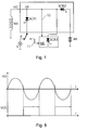
- Figure 1 shows the general diagram of an apparatus according to the invention for controlling the idle operating conditions of an internal-combustion engine of a motor vehicle, which is suitable for achieving the objects referred to above.
- the apparatus comprises a voltage regulator VR of any suitable type which is able to control the voltage VG output from a voltage generator which is represented by its winding W4 and which supplies, by means of a first controlled electronic switch SCR1, and a manually operable switch device IT, an alternating-current load L, for example consisting of the headlamps of a motor vehicle to which the apparatus is normally fitted.
- a voltage regulator VR of any suitable type which is able to control the voltage VG output from a voltage generator which is represented by its winding W4 and which supplies, by means of a first controlled electronic switch SCR1, and a manually operable switch device IT, an alternating-current load L, for example consisting of the headlamps of a motor vehicle to which the apparatus is normally fitted.
- the electrical system of the motor vehicle also comprises a power supply battery BA
- the latter is supplied by the generator winding W4 in a manner known per se, by means of a second controlled electronic switch SCR2.
- control unit ME for controlling the engine idle speed, which is able to perform the following functions:
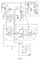
- the voltage regulator substantially comprises a number of functional blocks which are indicated by the reference letters A, B, C, D, E, F' H, N and which will be described separately, for controlling the output voltage VG from the winding W4 of a voltage magneto generator supplying an electric circuit with which a motor vehicle is normally equipped.
- ME denotes again the unit for controlling the engine idle speed, which by means of the connection 10 receives from the output voltage VG of the generator winding W4, a first information relating to the running speed of the engine, while by means of the connection 11 it receives from the deviator switch IT a further information relating to the connected or disconnected state of the load L depending on the position assumed by the switch IT itself.
- Fig. 2 AL denotes moreover a block for generating a voltage VS supplying the various functional blocks of the voltage regulator; the block AL comprises a diode DS and a resistor RS in series with a capacitor CS, the charging voltage VS of which is stabilised by a Zener diode DZS in parallel with the capacitor CS.
- the block A consists of a controlled electronic switch T1, for example SCR1 shown in Figure 1, which can be connected the AC load L in series to the winding W4 of the generator, through switch IT, so as to supply the AC load L as from a predefined instant during an electrical angle fraction of each positive half-wave of the output voltage VG from the generator winding W4, until the moment when there is no more current flowing through it.
- T1 controlled electronic switch
- the characteristic aspect of the series phase-control type voltage regulator shown consists in supplying of the AC electric load L by means of half-waves of a same polarity, and by effecting a control of the conduction phase of the electronic switch T1 for a fraction only of each half-wave, namely for an electrical angle during which the effective value of the generator voltage applied to the AC electric load L corresponds to the effective value of the voltage admissible for the load itself.
- the output V0 of the block B is supplied to the inlet of an inverting integrator comprising the circuit R1-C1 and an operational amplifier A1, the non-inverting terminal of which is connected to a voltage source VR1 which determines the effective value of the admissible voltage for the load L to be supplied.
- the output voltage V1 from the inverting integrator block C rises or falls depending on whether the mean of the voltage V0 is less or greater than the reference voltage VR1.
- the output V1 of the block C consisting of an inverting integrator is sent to the inlet of a block D comprising a signal inverting amplifier (A2, R2, R3) which inverts V1 with respect to a second reference voltage source VR2 and the amplification ratio of which is defined by: R3/R2 where R2 and R3 are connected to an operational amplifier A2, in the typical configuration of an inverting amplifier.
- A2, R2, R3 signal inverting amplifier
- V2 At the outlet of A2 there is a second control voltage V2 which, similar to V1, is related to the effective value of the voltage VL existing on the AC load L as defined above.
- the voltage V2 therefore varies, upon variation of V0 with respect to the reference voltage VR1, depending on whether the voltage generator represented by the winding W4 is operating idle, when T1 is reversely polarised, namely is open or deactivated, or whether current is flowing in the load L, when T1 is closed or in a conductive state.
- the voltage V2 is supplied to the non-inverting inlet of the comparator CP2 of the block F' which has, applied to its inverting inlet, a reference voltage VR3 which provides a threshold voltage suitable for determining the instant in which the battery BA is supplied following triggering of the switch T2.
- the output signal of the comparator CP2, by means of the diode D3, is then sent to the control electrode of the block H comprising of an electronic switch T2, such as SCR2 according to Figure 1, which is arranged in series with the battery BA, between the latter and the winding W4 of the voltage generator.
- an electronic switch T2 such as SCR2 according to Figure 1, which is arranged in series with the battery BA, between the latter and the winding W4 of the voltage generator.
- the voltage regulator according to Fig. 2 is also provided with a block N comprising a voltage comparator CP1 which compares the voltage ramp VC generated by a block E, with a voltage V3 provided by a block I.
- the block N is such that, when the voltage VC exceeds the voltage V3 of the output block I, which is directly related to the value of the voltage VB of the battery BA, it actutes the electronic switch T1 of the block A by means of the diode D1, causing it to switch on.
- the battery charging voltage is normally fixed at about 14.5 volts for batteries with a nominal voltage of 12 volts, when the electronic switch T2 is closed or in conductive state, the same voltage is also present on the AC load L, although, being limited to the positive half-waves alone, it does not allow the voltage VL of the AC load to exceed a desired value, for example of 13 volts, which is normally less than the charging voltage of the battery BA.
- the block E for generation of the voltage ramp VC for controlling the switching-on phase of T1 consists of an integrator RC-C2 for only the positive half-waves of the voltage VG of the generator, since the negative half-waves, which are intended to supply the electronic ignition circuit of the engine, are blocked by the diode DC.
- the block E also comprises a first transistor TR1 for short-circuiting the capacitor C2, the base of which is normally polarised, via the resistor R4, by the voltage VS supplying the various functional blocks of the circuit and in which the base of TR1 in turn is connected to the collector of a second transistor TR2 inhibiting the first transistor TR1, the base of which is polarised by the positive voltage of the generator by means of the resistor RG, while the diode D2 serves to protect TR2 during the negative half-waves.
- a first transistor TR1 for short-circuiting the capacitor C2, the base of which is normally polarised, via the resistor R4, by the voltage VS supplying the various functional blocks of the circuit and in which the base of TR1 in turn is connected to the collector of a second transistor TR2 inhibiting the first transistor TR1, the base of which is polarised by the positive voltage of the generator by means of the resistor RG, while the diode D2 serves to protect TR2 during the negative half-waves.
- the voltage VC from the block E therefore represents the integral value of the voltage VG of the generator, or more generally constitutes a voltage ramp which is related to the voltage VG of the generator and is set to zero every time the voltage VG of the generator becomes negative; in this way the block E is always ready to operate at each positive half-wave or more generally for all the half-waves of the generator voltage which have the same polarity.
- the block I in turn consists of an operational amplifier A3 which is connected to the resistors R5, R6, R7 and R8, as a differential amplifier which amplifies, with a suitable gain, the difference between the voltage VB relating to the charged state of the battery BA and a reference voltage VR4 indicative of the nominal voltage of the battery BA. More precisely it is found that: so that the output voltage V3 from the block I is:
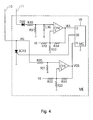
- the diagram according to Figure 2 also comprises a block ME for controlling the engine idle speed, shown in detail in Figure 4.
- the block ME controlling the engine idle speed comprises two voltage comparators CP3 and CP4 which are connected in an inverting configuration and with a hysteresis determined by the resistors R22, R23 and R24 and R32, R33 and R34, respectively, so that switching is performed without uncertainty.
- the signal VGS is sent to a first inlet I1 of a logic control unit, for example a microcontroller MC which is able to:
- the voltage VL present on the cathode of T1 is sent to the load L when the deviator switch IT is in the position shown, whereas it is sent to the anode of the diode D30 when the movable contact of T1 is switched to the "lamps OFF" position, opposite to the previous one.
- Figure 3 of the drawings shows a solution substantially similar to that of Figure 2, with the sole difference that in this case a voltage regulator of the series phase-control type for AC loads L alone is used.
- the voltage regulator according to Figure 3 also comprises the blocks A, B, C, D and E according to Figure 2, as well as the power supply block AL, differing in that now the output voltage V2 from the block D is supplied to the inverting terminal of the voltage comparator CP1 which forms part of the block F and the non-inverting terminal of which is in turn supplied with the voltage VC of the ramp generator E.
- the output voltage VS of the comparator CP1 is in this case directly supplied to the control terminal of the switch T1, again via the diode D1.
- the block ME controlling the engine idle speed shown in Figure 3 is formed in a manner identical to that of Figure 2, so that reference should be made to that previously stated both as regards the characteristics of this block and as regards its functions and the operating mode of the entire circuit.
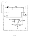
- Figures 5, 6 and 7 show a further solution which envisages a different method of detecting the connected and disconnected states of the AC electric load L, in which the deviator switch IT according to the previous example has been replaced by a simple switch. Therefore, in Figures 5 and 6 the same reference numbers have been used to indicate similar or equivalent parts.
- the circuit of the comparator CP3 also remains unchanged with respect to that of the preceding Figure 4, while the logic control unit MC now has a further output 01 able to feed a current of a few milliamperes, for example 5 to 10 milliamperes, through the resistor R25 and the diode D20, the switch IT and the load L, or towards the voltage regulator.
- the logic control unit MC is suitably preset so as to control the signal VGS provided on the inlet I1 by the comparator CP3, measure the running speed of the engine and check again whether the half-wave of the voltage VG of the generator is positive or negative. In this case, if the voltage VG is negative, there will certainly be no voltage on the AC load L since the electronic switch T1, being inhibited, is certainly not connected.
- the logic control unit MC during this phase may activate to the high logic level the outlet 01 so as to allow the flow of a current limited by the resistor R25, through D20 and the switch IT, towards the load L if said switch IT is closed so as to be connected to the load itself.
- the inlet I2 of the logic control unit will certainly recognise as low the logic level of the voltage present on the anode of the diode D20 and, by means of suitably programming of the said logic control unit MC, this level will be assimilated to the condition of electric load L connected, i.e. lamps lit.
- the diode 20 also has the function of protecting the logic control unit, for example the microcontroller MC, from the high peaks which are present on the load L, since said diode D2 is polarised in a reverse manner when the voltage on the load L exceeds that present on the anode of the diode itself.
- the logic control unit for example the microcontroller MC
- the apparatus is able to establish, using one of the two methods described above, whether the AC load L is connected or disconnected, namely whether the lamps are ON or OFF and determine the running speed of the engine.
- the internal-combustion engine is running at the idle speed. In these conditions, its running speed must be kept within well-defined limits which, for small engines with a capacity of 50 cc, typically lies between 1700 and 1900 revolutions per minute.
- the electric load L consisting of the lamps of the motor vehicle affects these idle speed values; therefore, when the load is not connected, it is necessary to ensure that the engine keeps its minimum speed within the predetermined limits, by connecting up to the generator winding W4 another load only in a well-defined speed range, so as to prevent power dissipation also when it is not required.
- the said speed of 1800 rpm must be maintained also when the lamps are switched off, i.e. with the AC load L disconnected; in this condition the block ME controlling the engine idle speed detects using one of the two methods described above, the condition where the load is disconnected or the lamps switched off, measures the running speed of the engine and, if said speed exceeds the minimum value of 1800 rpm mentioned above, namely exceeds the speed limits envisaged for that engine, then the electronic switch SCR3 is triggered so as to switch on.
- the apparatus thus conceived is able to perform braking of the internal-combustion engine without the use of additional electric loads, but only by short-circuiting to earth the voltage generator by means of a unidirectional electronic switch.
- Activation of the unidirectional electronic switch for braking of the internal-combustion engine moreover takes place only in the condition where the load is disconnected and with the minimum running speed of the engine lying within a predefined range of values.
- detection of the condition where the load is connected or disconnected may be performed by means of a deviator switch which connects the electric load to the input of a functional block controlling the idle speed of the engine, so as to provide said information to a logic control unit which is suitably programmed to manage operation of the entire apparatus controlling the engine idle speed.
- detection of the condition where the load L is connected or disconnected, or the lamps are switched on or off may be performed by reading the voltage drop upstream of the switch IT and the protection diode D20 of the logic control unit, which voltage drop is generated by a current with an extremely low value, which is provided by the said block ME controlling the engine idle speed when the electronic switch T1 of the voltage regulator is in turn inhibited, i.e. during the negative half-waves of the voltage output from the generator.
Landscapes
- Engineering & Computer Science (AREA)
- Chemical & Material Sciences (AREA)
- Combustion & Propulsion (AREA)
- Mechanical Engineering (AREA)
- General Engineering & Computer Science (AREA)
- Control Of Vehicle Engines Or Engines For Specific Uses (AREA)
- Control Of Eletrric Generators (AREA)
- Electrical Control Of Air Or Fuel Supplied To Internal-Combustion Engine (AREA)
Applications Claiming Priority (2)
| Application Number | Priority Date | Filing Date | Title |
|---|---|---|---|
| ITMI981409 | 1998-06-19 | ||
| IT98MI001409 IT1301760B1 (it) | 1998-06-19 | 1998-06-19 | Metodo e dispositivo per il controllo del minimo motore |
Publications (2)
| Publication Number | Publication Date |
|---|---|
| EP0965741A2 true EP0965741A2 (fr) | 1999-12-22 |
| EP0965741A3 EP0965741A3 (fr) | 2001-12-05 |
Family
ID=11380284
Family Applications (1)
| Application Number | Title | Priority Date | Filing Date |
|---|---|---|---|
| EP99107971A Withdrawn EP0965741A3 (fr) | 1998-06-19 | 1999-04-22 | procédé et dispositif de commande du régime ralenti d'un moteur a combustion interne |
Country Status (6)
| Country | Link |
|---|---|
| EP (1) | EP0965741A3 (fr) |
| JP (1) | JP2000027691A (fr) |
| CN (1) | CN1094560C (fr) |
| AR (1) | AR018418A1 (fr) |
| BR (1) | BR9902385A (fr) |
| IT (1) | IT1301760B1 (fr) |
Families Citing this family (3)
| Publication number | Priority date | Publication date | Assignee | Title |
|---|---|---|---|---|
| TWM351155U (en) * | 2001-11-14 | 2009-02-21 | Ind Tech Res Inst | Continuous transmission compound power system |
| JP2003154861A (ja) * | 2001-11-14 | 2003-05-27 | Ind Technol Res Inst | 並列式二動力ユニット複合動力システム |
| CN100402835C (zh) * | 2004-04-30 | 2008-07-16 | 揭阳市明珠机车配件有限公司 | 汽车、摩托车启动保护装置 |
Family Cites Families (5)
| Publication number | Priority date | Publication date | Assignee | Title |
|---|---|---|---|---|
| JPS57110736A (en) * | 1980-12-27 | 1982-07-09 | Fuji Heavy Ind Ltd | Apparatus for controlling rotational frequency of engine |
| JPH03222825A (ja) * | 1990-01-27 | 1991-10-01 | Hitachi Ltd | 車体振動低減装置 |
| US5582069A (en) * | 1994-05-16 | 1996-12-10 | Eaton Corporation | Engine accessory torque and engine deceleration rate determination method/system |
| IT1270142B (it) * | 1994-05-26 | 1997-04-29 | Ducati Energia Spa | Dispositivo per l'alimentazione di carichi elettrici e del circuito di accensione di motori a scoppio di veicoli a motore |
| DE19624343A1 (de) * | 1996-06-19 | 1998-01-02 | Mannesmann Vdo Ag | Leerlaufregelung in Abhängigkeit von elektrischen Verbrauchern |
-
1998
- 1998-06-19 IT IT98MI001409 patent/IT1301760B1/it active IP Right Grant
-
1999
- 1999-04-22 EP EP99107971A patent/EP0965741A3/fr not_active Withdrawn
- 1999-05-28 AR ARP990102557 patent/AR018418A1/es not_active Application Discontinuation
- 1999-06-10 CN CN99108352A patent/CN1094560C/zh not_active Expired - Fee Related
- 1999-06-18 JP JP11171793A patent/JP2000027691A/ja active Pending
- 1999-06-18 BR BR9902385-7A patent/BR9902385A/pt not_active IP Right Cessation
Non-Patent Citations (1)
| Title |
|---|
| None |
Also Published As
| Publication number | Publication date |
|---|---|
| JP2000027691A (ja) | 2000-01-25 |
| ITMI981409A1 (it) | 1999-12-19 |
| IT1301760B1 (it) | 2000-07-07 |
| CN1094560C (zh) | 2002-11-20 |
| CN1239755A (zh) | 1999-12-29 |
| BR9902385A (pt) | 2000-08-01 |
| AR018418A1 (es) | 2001-11-14 |
| EP0965741A3 (fr) | 2001-12-05 |
Similar Documents
| Publication | Publication Date | Title |
|---|---|---|
| EP0106539B1 (fr) | Système de régulation de tension pour générateur électrique | |
| US5089766A (en) | Vehicle ac generator control device with overvoltage limiter and dummy load unit | |
| JP4429387B2 (ja) | 三相発電機の出力電圧の制御装置 | |
| US4658200A (en) | Protection circuit for voltage regulator of vehicle mounted generator | |
| JPWO1999038239A1 (ja) | 車両用交流発電機の制御装置 | |
| JP3810441B2 (ja) | 電圧給電装置 | |
| US3942096A (en) | Voltage regulating system | |
| JPH1051976A (ja) | 車両用発電機の制御装置及びそれを用いた車両用発電装置 | |
| JP3627047B2 (ja) | 発電機の出力電圧を制御する電圧制御器 | |
| US5210480A (en) | Control device of vehicle mounted alternator | |
| CA1211154A (fr) | Regulateur pour alternateur a aimant permanent chargeur d'accumulateurs | |
| EP0965741A2 (fr) | procédé et dispositif de commande du régime ralenti d'un moteur a combustion interne | |
| US5173654A (en) | Voltage-regulator circuit for a system for recharging the battery of a motor vehicle | |
| US6111393A (en) | Phase-controlled voltage regulation with minimal energy loss | |
| JPH0715886A (ja) | 車両用発電機の出力電圧制御装置 | |
| JP3429434B2 (ja) | バッテリ電圧調整装置 | |
| JP3660456B2 (ja) | 二輪車用発電機の電圧調節回路 | |
| JP3399782B2 (ja) | 自動車用充電電圧制御回路 | |
| KR100465400B1 (ko) | 차량용 배터리의 과방전 방지장치 | |
| JP2661613B2 (ja) | 車両用発電機の制御装置 | |
| JP4037032B2 (ja) | 内燃機関の気化器用ヒーターの通電制御回路 | |
| KR920004326Y1 (ko) | 차량용 발전기의 전압 조정기 회로 | |
| KR19980020205A (ko) | 차량 교류발전기의 제어장치 | |
| JP3552658B2 (ja) | 車両用発電制御装置 | |
| JP2515397Y2 (ja) | コンデンサー充放電式点火装置 |
Legal Events
| Date | Code | Title | Description |
|---|---|---|---|
| PUAI | Public reference made under article 153(3) epc to a published international application that has entered the european phase |
Free format text: ORIGINAL CODE: 0009012 |
|
| AK | Designated contracting states |
Kind code of ref document: A2 Designated state(s): AT BE CH CY DE DK ES FI FR GB GR IE IT LI LU MC NL PT SE Kind code of ref document: A2 Designated state(s): AT DE ES FR IT SE |
|
| AX | Request for extension of the european patent |
Free format text: AL;LT;LV;MK;RO;SI PAYMENT 19990423 |
|
| PUAL | Search report despatched |
Free format text: ORIGINAL CODE: 0009013 |
|
| AK | Designated contracting states |
Kind code of ref document: A3 Designated state(s): AT BE CH CY DE DK ES FI FR GB GR IE IT LI LU MC NL PT SE |
|
| AX | Request for extension of the european patent |
Free format text: AL;LT;LV;MK;RO;SI PAYMENT 19990423 |
|
| 17P | Request for examination filed |
Effective date: 20020521 |
|
| AKX | Designation fees paid |
Free format text: AT DE ES FR IT SE |
|
| AXX | Extension fees paid |
Free format text: SI PAYMENT 19990423 |
|
| GRAP | Despatch of communication of intention to grant a patent |
Free format text: ORIGINAL CODE: EPIDOSNIGR1 |
|
| STAA | Information on the status of an ep patent application or granted ep patent |
Free format text: STATUS: THE APPLICATION IS DEEMED TO BE WITHDRAWN |
|
| 18D | Application deemed to be withdrawn |
Effective date: 20040622 |