EP0965744A1 - Schubumkehrvorrichtung für ein Bläsertriebwerk mit Umkehrklappen, die Kanäle mit veränderlichem Ausflussquerschnitt formen - Google Patents
Schubumkehrvorrichtung für ein Bläsertriebwerk mit Umkehrklappen, die Kanäle mit veränderlichem Ausflussquerschnitt formen Download PDFInfo
- Publication number
- EP0965744A1 EP0965744A1 EP99401489A EP99401489A EP0965744A1 EP 0965744 A1 EP0965744 A1 EP 0965744A1 EP 99401489 A EP99401489 A EP 99401489A EP 99401489 A EP99401489 A EP 99401489A EP 0965744 A1 EP0965744 A1 EP 0965744A1
- Authority
- EP
- European Patent Office
- Prior art keywords
- door
- internal
- thrust reverser
- external
- pivot
- Prior art date
- Legal status (The legal status is an assumption and is not a legal conclusion. Google has not performed a legal analysis and makes no representation as to the accuracy of the status listed.)
- Withdrawn
Links
- 238000011144 upstream manufacturing Methods 0.000 claims description 26
- 230000003416 augmentation Effects 0.000 claims 1
- 238000006073 displacement reaction Methods 0.000 description 3
- 230000000694 effects Effects 0.000 description 1
- 238000009432 framing Methods 0.000 description 1
- 238000009434 installation Methods 0.000 description 1
- 230000002787 reinforcement Effects 0.000 description 1
Images



Classifications
-
- F—MECHANICAL ENGINEERING; LIGHTING; HEATING; WEAPONS; BLASTING
- F02—COMBUSTION ENGINES; HOT-GAS OR COMBUSTION-PRODUCT ENGINE PLANTS
- F02K—JET-PROPULSION PLANTS
- F02K1/00—Plants characterised by the form or arrangement of the jet pipe or nozzle; Jet pipes or nozzles peculiar thereto
- F02K1/54—Nozzles having means for reversing jet thrust
- F02K1/64—Reversing fan flow
- F02K1/70—Reversing fan flow using thrust reverser flaps or doors mounted on the fan housing
Definitions
- the present invention relates to a device for reversing thrust of turbofan.
- the turbojet is fitted with a duct behind the blower, the purpose of which is to channel the secondary flow known as cold
- this conduit is consisting of an internal wall which surrounds the structure of the motor itself behind the blower, and a external wall whose upstream part comes in continuity with the crankcase that surrounds the blower.
- This outer wall can channel both the secondary flow and the flow primary in its downstream part, and this behind the ejection of the primary flow, called hot, in the case of nacelle with mixed flows or confluent flows for example, but in other cases, the external wall only channels the secondary flow, in the case of nacelles called flow separated.
- a wall can also cover the outside of the engine, this is to say the outside of the casing that surrounds the blower and the exterior of the exterior wall of the conduit described above, this in order to minimize the drag of the propulsion unit. This is particularly the case for propulsion systems added to the exterior of the aircraft, particularly when these propulsion systems are attached under the wings or at the rear of the fuselage.
- French patent application 96.09705 describes an example of realization, illustrated by FIG. 1 of the attached drawings, a thrust reverser with scoop doors, associated with a turbofan engine.
- the reversing device consists of a mobile assembly and of a fixed structure.
- the mobile assembly consists of hollow doors 3 forming a movable part 2 and constituting in the direct jet position, part of the outer casing of Platform.
- the fixed structure consists of a part upstream 6 upstream of the doors, of a downstream part 7 downstream of the doors 3 and beams which connect the upstream part 6 to the downstream part 7, the fixed structure also carrying out a part of the outer casing.
- the doors 3 are mounted on a circumference of the cowling outside and are pivotally mounted in a downstream area of their side walls on the beams connecting the downstream part 7 at the upstream part 6 of the outer cowling situated on the side and other of these doors, these side walls connect the external part or external panel 4 of the doors 3, which constitutes a part of the external wall of the nacelle to the interior part 5 of the doors 3 which constitutes a part of the outer wall of the duct.
- the upstream part 6 of fixed structure comprises a front frame 8 which can serve as a support for the control means of the displacements of doors 3, constituted for example by cylinders. These means for controlling the movement of the doors 3 can also be located in other places on the outskirts of door 3, for example downstream thereof. In that case it is the downstream structure 7 of fixed structure which can support the control elements.
- the doors 3 swing in such a way that the part of the doors located upstream of the pivots 9 comes more or less completely obstruct the duct while clearing a passage in the outer casing so as to allow the secondary stream 13 and 14 respectively to be channeled in a centrifugal direction with respect to the axis of the conduit on the one hand in the conduit or nozzle 10 formed by the structure of door 3 and between the deflection edge and the external of the external structure 4 of the door 3 else go.
- the downstream part of the doors comes in the vicinity of the outside of the outer casing.
- the pivot angle of the doors is adjusted so as to allow passage of the flow and so as to greatly reduce or even eliminate the thrust of this flow, and to generate a counter thrust in producing a component of the flow diverted upstream.
- nacelle lines including the thrust reverser must be adapted to the conditions aerodynamics of optimal performance for flight, which commonly leads to a narrowing of the lines of the external structure of the inverter in the downstream direction of the carrycot.
- the door scoop 3 which the upstream pivots in a centripetal direction relative to the geometric axis of the nacelle therefore ends up with a exhaust cross section shown in S2 smaller than the input section shown in S1.
- One of the aims of the invention is to obtain a increased aerodynamic performance of doors scoops, during reverse thrust operation the inverter, while respecting the conditions noted above.
- a thrust reverser of turbojet engines with scoop doors of the aforementioned type characterized in that at least a downstream part of the external structure of the door, which forms said internal conduit for guiding the flow through the door, is independent and movable relative to the internal structure of the door, so that the downstream section S2 of efficient exhaust outlet of the internal door duct, on the one hand, in the direct jet position, less than the upstream section S1 of the entry of the internal door duct, corresponding to the tightening of the nacelle external lines downstream and, on the other hand, in the reverse jet position after increase, at least equal to the inlet section S1, said movable part of the external door structure being driven in a centrifugal direction relative to the internal door structure by means a mechanical drive system.
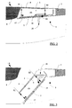
- FIGS 2,3,6 and 7 show an embodiment of the invention.
- a scoop door 3 formed of an internal main structure articulated around an axis of rotation 9 carried by the lateral beams of the fixed structure 6, drives and supports an external structure 4 articulated in this configuration around an axis 17 carried by the main internal structure 5 of the door 3.
- a covering 24 making it possible to plug the side walls of the structure of the door 3 in reverse jet is applied to one or the other of the structures.
- a grid of blades 18 is positioned inside the structure of the external nacelle, fixedly mounted on the downstream fixed structure 7 of the reverser. The arrangement of the blades is such that it allows the flow passing through the increased exhaust section "S2" of the internal duct 10 of the door 3 to be completely guided upstream of the nacelle.
- At least one roller 19 belonging to the external structure 4 is mounted in the lateral part downstream and opposite the pivot axis 17 of said external structure.
- At least one guide ramp 20 subject to the fixed structure of the reverser guides the roller 19 during the actuation phase of the door 3.
- the distance from the pivot 9 of the door 3 to the roller 19 in the ramp 20 in the jet position direct is smaller than the distance of the same pivot 9 from the door 3 to the roller 19 in the ramp 20 in the reverse jet position. The difference between these two values making it possible to achieve the desired "S2" exhaust section.
- the definition of the guide path is determined to allow suitable kinematics of the downstream of the external structure 4 relative to the blades of the grid 18.
- the axis of rotation 17 of the external structure can be replaced by a set of associated connecting rods, one of which would connect the internal structure 5 of the door 3 to the external structure 4 of the door and the second linked to the fixed structure would control the displacement of the first connecting rod, this in
- the movable external structure 4 can also cover only part of the total external structure of the door 3.
- the pivot axis 17 is displaced downstream of the internal structure 5, an overlap of the external structure fixed upstream with the movable external structure 4 can be applied to achieve aerodynamic continuity of the nacelle lines.
- the concept of guidance by ramp 20 defined above is advantageously suitable for rental of a low gate 18, that is to say being located closer to the internal of the internal structure 5 than the external structure 4 of the door.
- the envelope of the ramp 20 may be contained in the side walls of the fixed structure of the inverter.
- the grid 18 is positioned high, that is to say close to the internal of the movable external structure 4, the downstream of said movable external structure must have sufficiently clear kinematics to jump the obstacle of the dawn upstream of the grid 18.
- the guide ramp 20 may be unsuitable for this situation, the latter having to be found outside the lines of the nacelle.
- Figures 4 and 5 show a exemplary embodiment of another embodiment of the invention.
- At at least one connecting rod 21 is articulated on the fixed structure 6 at pivot point 22.
- pivot 22 is located at closer to the outer lines and on at least one wall side of the inverter structure.
- the connecting rod 21 is connected to the movable external structure 4 at point 23.
- the pivot point 23 can then exit the nacelle lines if necessary and thus allow sufficient clearance of the downstream of the movable external structure 4 of the door 3 around the grid 18.
- Figures 8, 9 10 and 11 show an example of downstream drive arrangement of the door by upstream cylinder.
- a jack 30 fixed and articulated on the fixed structure 6 at a point 33, rotates the door 3 around its pivot 9 by a point 32 positioned downstream of the structure of the door 3.
- the jack 30 can be positioned in the axis of the door 3, this in order to obtain a distance between the pivot 9 and the operating point. 32 of the door as large as possible.
- the definition of the mobile external structure 4 includes a central structural interruption to allow the housing of the jack 30.
- the mobile external structure 4 can be produced in two independent half-pieces 4a and 4b, each driven either by the principle already mentioned or by playing on the differential rotation of the actuator 30 and of the door 3 between the two open and closed positions.
- An intermediate pivot 17b taking up the lateral internal walls of the mobile external structure 4 framing the jack 30 serves both as a pivot relay and as structural reinforcement for the mobile half-structures as well as for the monobloc mobile structure.
- a fairing 31 is associated with the body of the jack.
- the internal face of said fairing 31 can have an aerodynamic shape to aid the flow and bypass of the flow as close as possible to its functional geometric definition.
- FIGS 12, 13, 14 and 15 show an embodiment of the invention allowing the concept of increasing the exhaust section "S2" to be associated with an upstream cylinder positioning 30 with drive linked to the internal structure 5, the axis of the jack in the direct jet position passes below the pivot axis 9 of the door 3.
- the pivot fittings are each positioned between the central axis of the door 3 and its respective side walls of an embodiment known to those skilled in the art.
- the jack 30 is positioned on the fixed structure 6 articulated at point 33 on the front frame 8.
- the attachment point 32 on the internal of the internal structure 5 is positioned between the upstream of the internal structure and the pivot 9.
- the two points 32 and 33 are positioned so that in direct jet the axis passing through these points is located under the pivot 9 of the door 3.
- the application of a scoop door technology with pivot axis 9 "raised” greatly reduces the natural clearance of the downstream vanes of the grid 18 relative to the cap 16 in reverse jet.
- a cavity in direct jet remains between these two curves.
- the use of a downstream cap 40 forming part of the external lines of the nacelle as defined in French patent application 97.06943 makes it possible to fill this cavity.
- the kinematics of drive by connecting rods makes it possible to associate the operation of the external structure 4.
- the cap comprises two points of driving and guiding 41 and 42.
- a connecting rod 43 connects the point 43 to the door 3 to the point 46 and another connecting rod 50 connects point 41 downstream of the mobile external structure 4 at point 49.
- a third connecting rod 44 linked to the connecting rod 50 at point 41 has a fixed point of articulation 45 linked to the fixed structure 6.
- a fourth connecting rod 47 is installed articulated on the connecting rod 43 at an intermediate point 48 between the two points 42 and 46 of this connecting rod.
- the connecting rod 47 is connected at point 49 to the movable external structure 4.
- the distance defined between point 46 and the pivot 48 of the connecting rod 47 allows, thanks to the angle formed between the direct jet and reverse jet position, to ensure an increase of the exhaust section "S2".
- the internal surface of the internal structure 5 can be continuous and come into contact with a blade 51 producing the usual internal surface of the door 3.
- the jack 30 in this configuration creates a local cavity on the external surface of the nacelle.
- a fairing 31 taking up part of the external lines of the nacelle fills this cavity.
- the fairing 31 can be fixed on the jack 30. It can be associated with the fixed upstream structure and be cantilevered. It can also be connected and articulated on the upstream side of the mobile external structure 4, the upstream side of the fairing 31 being able to be guided on the body of the jack 30.
- the blade grid 18 instead of being fixed is mounted integral with the door 3. Either the whole grid 18 is mounted to one of the structures 4 or 5 of the door 3, or each structure 4 and 5 of the door 3 support part of the grid 18 and moves during the opening to cooperate with each other while respecting the opening kinematics.
Landscapes
- Engineering & Computer Science (AREA)
- Chemical & Material Sciences (AREA)
- Combustion & Propulsion (AREA)
- Mechanical Engineering (AREA)
- General Engineering & Computer Science (AREA)
- Wind Motors (AREA)
- Structures Of Non-Positive Displacement Pumps (AREA)
- Power-Operated Mechanisms For Wings (AREA)
Applications Claiming Priority (2)
| Application Number | Priority Date | Filing Date | Title |
|---|---|---|---|
| FR9807659A FR2780101B1 (fr) | 1998-06-18 | 1998-06-18 | Inverseur de poussee de turboreacteur a portes formant ecopes a section d'echappement adaptable |
| FR9807659 | 1998-06-18 |
Publications (1)
| Publication Number | Publication Date |
|---|---|
| EP0965744A1 true EP0965744A1 (de) | 1999-12-22 |
Family
ID=9527515
Family Applications (1)
| Application Number | Title | Priority Date | Filing Date |
|---|---|---|---|
| EP99401489A Withdrawn EP0965744A1 (de) | 1998-06-18 | 1999-06-17 | Schubumkehrvorrichtung für ein Bläsertriebwerk mit Umkehrklappen, die Kanäle mit veränderlichem Ausflussquerschnitt formen |
Country Status (4)
| Country | Link |
|---|---|
| US (1) | US6158211A (de) |
| EP (1) | EP0965744A1 (de) |
| CA (1) | CA2274767A1 (de) |
| FR (1) | FR2780101B1 (de) |
Cited By (2)
| Publication number | Priority date | Publication date | Assignee | Title |
|---|---|---|---|---|
| FR2965304A1 (fr) * | 2010-09-23 | 2012-03-30 | Airbus Operations Sas | Dispositif de decharge d'air pour turboreacteur d'avion a double flux |
| WO2013045787A1 (fr) | 2011-09-29 | 2013-04-04 | Aircelle | Portes d'inverseur de poussée à ouvertures latérales |
Families Citing this family (17)
| Publication number | Priority date | Publication date | Assignee | Title |
|---|---|---|---|---|
| US8015797B2 (en) | 2006-09-21 | 2011-09-13 | Jean-Pierre Lair | Thrust reverser nozzle for a turbofan gas turbine engine |
| JP5467490B2 (ja) * | 2007-08-03 | 2014-04-09 | 日本電気硝子株式会社 | 強化ガラス基板の製造方法及び強化ガラス基板 |
| US8091827B2 (en) | 2007-11-16 | 2012-01-10 | The Nordam Group, Inc. | Thrust reverser door |
| US8052085B2 (en) | 2007-11-16 | 2011-11-08 | The Nordam Group, Inc. | Thrust reverser for a turbofan gas turbine engine |
| US8172175B2 (en) | 2007-11-16 | 2012-05-08 | The Nordam Group, Inc. | Pivoting door thrust reverser for a turbofan gas turbine engine |
| US8052086B2 (en) | 2007-11-16 | 2011-11-08 | The Nordam Group, Inc. | Thrust reverser door |
| US7735778B2 (en) | 2007-11-16 | 2010-06-15 | Pratt & Whitney Canada Corp. | Pivoting fairings for a thrust reverser |
| US8051639B2 (en) | 2007-11-16 | 2011-11-08 | The Nordam Group, Inc. | Thrust reverser |
| US8127530B2 (en) | 2008-06-19 | 2012-03-06 | The Nordam Group, Inc. | Thrust reverser for a turbofan gas turbine engine |
| US10041442B2 (en) * | 2010-06-11 | 2018-08-07 | United Technologies Corporation | Variable area fan nozzle |
| US8904751B2 (en) * | 2012-04-30 | 2014-12-09 | Middle River Aircraft Systems | Thrust reverser assembly and method of operation |
| US10309343B2 (en) | 2014-11-06 | 2019-06-04 | Rohr, Inc. | Split sleeve hidden door thrust reverser |
| US10343786B2 (en) * | 2017-06-28 | 2019-07-09 | General Electric Company | System and method of operating a ducted fan propulsion system during aircraft taxi |
| GB2564891A (en) * | 2017-07-26 | 2019-01-30 | Short Brothers Plc | Nacelle with thrust reverser |
| EP4039962B1 (de) * | 2021-02-09 | 2024-11-13 | Rohr, Inc. | Flüssigkeitsschöpfer für ein schubumkehrsystem |
| FR3130902A1 (fr) * | 2021-12-22 | 2023-06-23 | Safran Nacelles | Nacelle pour ensemble propulsif d’aéronef comprenant un volet pour obturer un évidement de passage d’un organe mécanique |
| FR3137134B1 (fr) * | 2022-06-22 | 2024-05-17 | Safran Nacelles | Inverseur de poussee comprenant au moins une membrane deployable de deviation |
Citations (1)
| Publication number | Priority date | Publication date | Assignee | Title |
|---|---|---|---|---|
| EP0822327A1 (de) * | 1996-08-01 | 1998-02-04 | Hispano-Suiza | Schubumkehrvorrichtung für ein Bläsertriebwerk mit Umkehrklappen, die Kanäle formen |
Family Cites Families (2)
| Publication number | Priority date | Publication date | Assignee | Title |
|---|---|---|---|---|
| FR2764341B1 (fr) * | 1997-06-05 | 1999-07-16 | Hispano Suiza Sa | Inverseur de poussee de turboreacteur a portes formant ecopes associees a un deflecteur mobile |
| US5987880A (en) * | 1997-07-08 | 1999-11-23 | Mcdonnell Douglas Corporation | Supersonic engine, multi-port thrust reversing system |
-
1998
- 1998-06-18 FR FR9807659A patent/FR2780101B1/fr not_active Expired - Fee Related
-
1999
- 1999-06-15 CA CA002274767A patent/CA2274767A1/fr not_active Abandoned
- 1999-06-16 US US09/333,921 patent/US6158211A/en not_active Expired - Fee Related
- 1999-06-17 EP EP99401489A patent/EP0965744A1/de not_active Withdrawn
Patent Citations (1)
| Publication number | Priority date | Publication date | Assignee | Title |
|---|---|---|---|---|
| EP0822327A1 (de) * | 1996-08-01 | 1998-02-04 | Hispano-Suiza | Schubumkehrvorrichtung für ein Bläsertriebwerk mit Umkehrklappen, die Kanäle formen |
Cited By (3)
| Publication number | Priority date | Publication date | Assignee | Title |
|---|---|---|---|---|
| FR2965304A1 (fr) * | 2010-09-23 | 2012-03-30 | Airbus Operations Sas | Dispositif de decharge d'air pour turboreacteur d'avion a double flux |
| US8925295B2 (en) | 2010-09-23 | 2015-01-06 | Airbus Operations | Air discharging device for an aircraft double-flow turbine engine |
| WO2013045787A1 (fr) | 2011-09-29 | 2013-04-04 | Aircelle | Portes d'inverseur de poussée à ouvertures latérales |
Also Published As
| Publication number | Publication date |
|---|---|
| FR2780101B1 (fr) | 2000-07-28 |
| FR2780101A1 (fr) | 1999-12-24 |
| US6158211A (en) | 2000-12-12 |
| CA2274767A1 (fr) | 1999-12-18 |
Similar Documents
| Publication | Publication Date | Title |
|---|---|---|
| EP0853192B1 (de) | Schubumkehrvorrichtung mit optimierter Anordnung des Gitterbetätigungsorgans | |
| EP0822327B1 (de) | Schubumkehrvorrichtung für ein Bläsertriebwerk mit Umkehrklappen, die Kanäle formen | |
| CA2225608C (fr) | Inverseur de poussee de turboreacteur a double flux a coquilles aval | |
| CA2191179C (fr) | Inverseur de poussee de turboreacteur a portes a panneau arriere articule | |
| FR2780101A1 (fr) | Inverseur de poussee de turboreacteur a portes formant ecopes a section d'echappement adaptable | |
| EP0806563B1 (de) | Klappen mit Leitflächen für eine Schubumkehrvorrichtung eines Bläsertriebwerkes | |
| WO1999046498A1 (fr) | Inverseur de poussee de turboreacteur a portes formant ecopes associees a une grille mobile | |
| CA2267550A1 (fr) | Inverseur de poussee de turboreacteur a portes formant ecopes associees a un capotage externe articule | |
| EP0882883A1 (de) | Schubumkehrvorrichtung für ein Strahltriebwerk dessen Umkehrklappen mit je einer entfaltbaren Leitfläche versehen sind | |
| WO1998015731A1 (fr) | Inverseur de poussee a portes a debit de fuite controle | |
| EP0882881A1 (de) | Hubumkehrvorrichtung für ein Strahltriebwerk dessen Umkehrklappen mit optimalentfaltbaren Leitflächen versehen sind | |
| EP0882882A1 (de) | Schubumkehrvorrichtung für ein Strahltriebwerk dessen Umkehrklappen mit je einer, an der Vorderseite der Hauptklappen verbundenen, entfaltbaren Leitfläche versehen sind | |
| EP0761957A1 (de) | Schubumkehrvorrichtung für ein Strahltriebwerk von mit dem Vorderteil verbundenen Klappen | |
| EP0764779A1 (de) | Schubumkehrvorrichtung mit einem mit Primärteil verbundenen Klappen | |
| CA2286381A1 (fr) | Inverseur de poussee de turboreacteur a obstacles aval | |
| EP0807753A1 (de) | Eine Klappe einer Schubumkehrvorrichtung hat eine Auskleidung, die scharnierend an einem Längsträger befestigt ist | |
| EP0835999B1 (de) | Schubumkehrvorrichtung mit optimalisierter Anordnung des Betätigungsorgans | |
| EP0821151A1 (de) | Schubumkehrvorrichtung für ein Strahltriebwerk mit Klappen mit verschiebbarem Wandteil | |
| EP0728933B1 (de) | Schubumkehrvorrichtung mit dem Hinterteil verbundenen Klappen | |
| FR2757570A1 (fr) | Inverseur de poussee de turboreacteur a guidage du flux d'inversion ameliore | |
| FR2750737A1 (fr) | Inverseur de poussee de turboreacteur a portes a pilotage de nappes ameliore |
Legal Events
| Date | Code | Title | Description |
|---|---|---|---|
| PUAI | Public reference made under article 153(3) epc to a published international application that has entered the european phase |
Free format text: ORIGINAL CODE: 0009012 |
|
| 17P | Request for examination filed |
Effective date: 19990701 |
|
| AK | Designated contracting states |
Kind code of ref document: A1 Designated state(s): DE FR GB |
|
| AX | Request for extension of the european patent |
Free format text: AL;LT;LV;MK;RO;SI |
|
| AKX | Designation fees paid |
Free format text: DE FR GB |
|
| GRAH | Despatch of communication of intention to grant a patent |
Free format text: ORIGINAL CODE: EPIDOS IGRA |
|
| GRAP | Despatch of communication of intention to grant a patent |
Free format text: ORIGINAL CODE: EPIDOSNIGR1 |
|
| STAA | Information on the status of an ep patent application or granted ep patent |
Free format text: STATUS: THE APPLICATION IS DEEMED TO BE WITHDRAWN |
|
| 18D | Application deemed to be withdrawn |
Effective date: 20031129 |