EP0965751A2 - Injecteur de combustible - Google Patents
Injecteur de combustible Download PDFInfo
- Publication number
- EP0965751A2 EP0965751A2 EP99303391A EP99303391A EP0965751A2 EP 0965751 A2 EP0965751 A2 EP 0965751A2 EP 99303391 A EP99303391 A EP 99303391A EP 99303391 A EP99303391 A EP 99303391A EP 0965751 A2 EP0965751 A2 EP 0965751A2
- Authority
- EP
- European Patent Office
- Prior art keywords
- needle
- spring
- fuel
- valve
- fuel injector
- Prior art date
- Legal status (The legal status is an assumption and is not a legal conclusion. Google has not performed a legal analysis and makes no representation as to the accuracy of the status listed.)
- Granted
Links
Images
Classifications
-
- F—MECHANICAL ENGINEERING; LIGHTING; HEATING; WEAPONS; BLASTING
- F02—COMBUSTION ENGINES; HOT-GAS OR COMBUSTION-PRODUCT ENGINE PLANTS
- F02M—SUPPLYING COMBUSTION ENGINES IN GENERAL WITH COMBUSTIBLE MIXTURES OR CONSTITUENTS THEREOF
- F02M57/00—Fuel-injectors combined or associated with other devices
- F02M57/02—Injectors structurally combined with fuel-injection pumps
-
- F—MECHANICAL ENGINEERING; LIGHTING; HEATING; WEAPONS; BLASTING
- F02—COMBUSTION ENGINES; HOT-GAS OR COMBUSTION-PRODUCT ENGINE PLANTS
- F02M—SUPPLYING COMBUSTION ENGINES IN GENERAL WITH COMBUSTIBLE MIXTURES OR CONSTITUENTS THEREOF
- F02M61/00—Fuel-injectors not provided for in groups F02M39/00 - F02M57/00 or F02M67/00
- F02M61/16—Details not provided for in, or of interest apart from, the apparatus of groups F02M61/02 - F02M61/14
- F02M61/18—Injection nozzles, e.g. having valve seats; Details of valve member seated ends, not otherwise provided for
-
- F—MECHANICAL ENGINEERING; LIGHTING; HEATING; WEAPONS; BLASTING
- F02—COMBUSTION ENGINES; HOT-GAS OR COMBUSTION-PRODUCT ENGINE PLANTS
- F02M—SUPPLYING COMBUSTION ENGINES IN GENERAL WITH COMBUSTIBLE MIXTURES OR CONSTITUENTS THEREOF
- F02M57/00—Fuel-injectors combined or associated with other devices
- F02M57/02—Injectors structurally combined with fuel-injection pumps
- F02M57/022—Injectors structurally combined with fuel-injection pumps characterised by the pump drive
- F02M57/023—Injectors structurally combined with fuel-injection pumps characterised by the pump drive mechanical
-
- F—MECHANICAL ENGINEERING; LIGHTING; HEATING; WEAPONS; BLASTING
- F02—COMBUSTION ENGINES; HOT-GAS OR COMBUSTION-PRODUCT ENGINE PLANTS
- F02M—SUPPLYING COMBUSTION ENGINES IN GENERAL WITH COMBUSTIBLE MIXTURES OR CONSTITUENTS THEREOF
- F02M59/00—Pumps specially adapted for fuel-injection and not provided for in groups F02M39/00 -F02M57/00, e.g. rotary cylinder-block type of pumps
- F02M59/20—Varying fuel delivery in quantity or timing
- F02M59/36—Varying fuel delivery in quantity or timing by variably-timed valves controlling fuel passages to pumping elements or overflow passages
- F02M59/366—Valves being actuated electrically
-
- F—MECHANICAL ENGINEERING; LIGHTING; HEATING; WEAPONS; BLASTING
- F02—COMBUSTION ENGINES; HOT-GAS OR COMBUSTION-PRODUCT ENGINE PLANTS
- F02M—SUPPLYING COMBUSTION ENGINES IN GENERAL WITH COMBUSTIBLE MIXTURES OR CONSTITUENTS THEREOF
- F02M61/00—Fuel-injectors not provided for in groups F02M39/00 - F02M57/00 or F02M67/00
- F02M61/16—Details not provided for in, or of interest apart from, the apparatus of groups F02M61/02 - F02M61/14
- F02M61/20—Closing valves mechanically, e.g. arrangements of springs or weights or permanent magnets; Damping of valve lift
- F02M61/205—Means specially adapted for varying the spring tension or assisting the spring force to close the injection-valve, e.g. with damping of valve lift
Definitions
- This invention relates to a fuel injector for use in supplying fuel under pressure to a combustion space of a compression ignition internal combustion engine.
- the invention relates to a fuel injector of the type in which the commencement of injection is controlled using an electromagnetic actuator.
- the invention is particularly suitable for use in a pump/injector arrangement, but it will be appreciated that the invention may be used in other applications.
- the commencement of injection is controlled by controlling the fuel pressure within a control chamber, the fuel pressure within the control chamber applying a force to a valve needle urging the needle towards its seating.
- the fuel pressure within the control chamber is controlled using an appropriate electromagnetically actuated valve.
- a fuel injector comprising a valve needle biased by a spring towards a seating, and an electromagnetic actuator arrangement arranged to vary the magnitude of the biasing force applied to the needle by the spring.
- the spring is conveniently arranged to apply a sufficiently large biasing force to the needle to ensure that injection does not occur when the actuator is energised to a first energization level.
- the actuator Upon energizing the actuator to a second energization level, the actuator acts against the spring to reduce the magnitude of the biasing force applied to the needle by the spring to a level sufficient to allow movement of the injector needle thus allowing injection to commence.
- the actuator includes an armature carried by a control member, the spring load being transmitted to the needle through the control member.
- the fuel injector does not rely upon the operation of a valve to control injection, the number of drillings, bores and other features which must be provided in the injector can be reduced thereby simplifying construction.
- the fuel injector is further relatively easy to control, thus permitting accurate control of the timing of injection.
- the invention is particularly suitable for use in a pump/injector arrangement in which the timing of fuel injection relative to the timing of closing a drain valve controls the injection pressure.
- the invention permits improved control of the injection pressure.
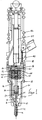
- the fuel injector illustrated in the accompanying drawings comprises a nozzle body 10 which is provided with a blind bore 12.
- a valve needle 14 is slidable within the bore and is engageable with a seating defined adjacent the blind end of the bore to control communication between the bore 12 and one or more outlet openings which communicate with the bore 12 downstream of the seating.
- the bore 12 is shaped to define an upper region of diameter substantially equal to the diameter of the adjacent part of the needle 14 which guides the needle 14 for sliding movement in the bore 12.
- This part of the bore 12 is shaped to define an annular gallery 16 which communicates with a supply passage 18.
- the bore 12 further defines a lower region of enlarged diameter which houses a reduced diameter portion of the needle 14 and defines with the adjacent part of the needle 14, a chamber from which fuel is supplied, in use, past the seating to the outlet openings.
- the valve needle 14 is shaped to include a plurality of flutes which define flow paths between the annular gallery 16 and the chamber defined between the lower part of the bore 12 and the adjacent part of the needle 14. At the intersection between the upper, relatively large diameter part of the needle 14 and the reduced diameter part thereof, a thrust surface is defined which is exposed to the fuel pressure within the chamber.
- the upper surface of the nozzle body 10 abuts a distance piece 20 which is provided with a through bore into which an end part of the needle 14 extends.
- a load transmitting member 22 engages the upper part of the needle 14 and is located in a part of the bore of the distance piece 20 of enlarged diameter.
- Drillings 24 are provided in the distance piece 20, the drillings 24 communicating with the supply passage 18.
- the upper surface of the distance piece 20 abuts the lower end surface of a second distance piece 26 which is provided with drillings 28 communicating with the drillings 24 of the first distance piece 20.
- the second distance piece 26 is further provided with a through bore which includes a region of relatively large diameter defining a spring chamber 30.
- a control member 32 extends into the spring chamber, the lower end of the control member 32 including an outwardly extending flange 34, the upper surface of which carries a shim 36, a helical compression spring being engaged between a step defined at an end of the spring chamber 30 and the upper surface of the shim 36.
- the spring 38 biases the member 32 in a downward direction in the orientation illustrated, biasing the lower end surface of the member 32 into engagement with the load transmitting member 22, hence biasing the valve needle 14 into engagement with the seating.
- the upper end of the control member 32 defines a step with which a shim 40 engages, the shim acting to locate an armature 42, a screw-threaded member 44 securing the armature 42 and shim 40 to the member 32.
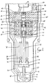
- the armature 42 is moveable under the influence of a magnetic field generated, in use, by a first winding 46 forming part of an actuator arrangement 48 located within an actuator housing 50.
- a passage 52 extends through the actuator housing 50, the passage 52 communicating with the drillings 28.
- the upper surface of the actuator housing 50 abuts a valve housing 54 which includes a drilling 56 communicating with the passage 52.
- the valve housing includes a through bore 58 within which a valve member 60 is slidable, the valve member 60 including a region which is dimensioned to engage a seating defined by part of the through bore 58.
- the through bore 58 and valve member 60 together define an annular chamber 62 located upstream of the seating which communicates through a drilling 64 and a recess 66 formed in the upper surface of the valve housing 54 with the drilling 56.
- the lower end of the valve member 60 is secured to an armature 68 by means of a screw-threaded member 70 which engages a screw-threaded part of the valve member 60.
- the armature 68 is moveable under the influence of a magnetic field generated, in use, by a second winding 72 forming part of the actuator 48.
- a shim 74 is located beneath the screw-threaded member 70, a helical compression spring 76 being engaged between the shim 74 and the upper surface of the screw-threaded member 44.
- valve housing 54 abuts the lower end of a pump housing 78 which includes a bore 80 within which a pumping plunger 82 reciprocal under the influence of a cam and tappet arrangement, against the action of a return spring 84.
- the shims 36, 40, 74 are selected depending upon the intended application of the injector, the shims setting the prestressing of the springs 38, 76 and the travel of the control member 32.
- valve member 60 In use, whilst the plunger 82 is being withdrawn from the plunger bore 80 under the action of the spring 84, and with the first and second windings 46, 72 of the actuator 48 de-energized, the valve member 60 is biased by the spring 76 away from the seating, thus permitting communication between a source of fuel under low pressure which communicates with a chamber 86 located downstream of the seating and the plunger bore 80. As a result, fuel flows to the plunger bore 80, the flow of fuel continuing until the plunger 82 reaches its outermost position. It will be appreciated that during this stage of the operation of the injector, the fuel pressure applied to the valve needle 14, and in particular to the angled thrust surfaces thereof exposed to the fuel pressure within the bore 12, is relatively low. The force applied to the valve needle 14 by the application of fuel under pressure is therefore insufficient to lift the valve needle 14 away from its seating, the spring 38 acting to ensure that the valve needle 14 remains in engagement with the seating.
- the first winding 46 When injection is to commence, the first winding 46 is energized attracting the armature 42 towards the winding 46. This attractive force is transmitted through the control member 32 to the spring 38, and it will be appreciated that as a result, the biasing force applied to the needle 14 by the spring 38 is reduced.
- the reduction in the biasing force applied to the needle 14 is sufficient to permit the valve needle 14 to lift from its seating under the action of the fuel pressure within the bore 12. Such movement of the needle 14 allows fuel to flow past the seating to the outlet openings, thus commencing injection.
- the second winding 72 is de-energized, and as a result the valve member 60 lifts away from its seating under the action of the spring 76.
- the movement of the valve member 60 permits fuel to escape to the low pressure fuel reservoir, thus permitting a rapid reduction in the fuel pressure within the plunger bore 80 and other passages within the injector.
- the fuel pressure applied to the needle 14 therefore falls, and as a result of the reduced pressure applied to the needle 14, the needle 14 returns into engagement with its seating under the action of the spring 38 to terminate injection.
- the first winding 46 may also be de-energized when the second winding 72 is de-energized, thus increasing the magnitude of the biasing force applied to the valve needle 14 by the spring 38 at the termination of injection.
- the timing at which commencement of injection occurs can be controlled relatively accurately, even allowing for slight inaccuracies in the effective area of the valve needle 14 exposed to the fuel pressure within the bore 12 urging the needle 14 away from its seating.
- the injection pressure can also be controlled accurately using the apparatus described hereinbefore.
- the first winding 46 may be continuously energized to ensure that injection commences as soon as a predetermined pressure is reached, the predetermined pressure being dependent upon the rate of the spring 38, the magnitude of the attractive force between the actuator 48 and armature 42, and the effective area of the valve needle 14 exposed to the fuel pressure within the bore 12.
- the magnitude of the attractive force between the actuator 48 and the armature 42 can be varied, in use, to vary the pressure at which commencement of injection occurs.
- the invention is incorporated into a pump injector arrangement, it will be appreciated that the invention is also applicable to other types of fuel injector in which the commencement of injection is controlled electronically, the invention being applicable to arrangements both where the timing of commencement of injection is controlled and arrangements in which commencement of injection is to occur when a predetermined pressure is reached.
Landscapes
- Engineering & Computer Science (AREA)
- Chemical & Material Sciences (AREA)
- Combustion & Propulsion (AREA)
- Mechanical Engineering (AREA)
- General Engineering & Computer Science (AREA)
- Fuel-Injection Apparatus (AREA)
Applications Claiming Priority (2)
| Application Number | Priority Date | Filing Date | Title |
|---|---|---|---|
| GB9812901 | 1998-06-15 | ||
| GBGB9812901.8A GB9812901D0 (en) | 1998-06-15 | 1998-06-15 | Fuel injector |
Publications (3)
| Publication Number | Publication Date |
|---|---|
| EP0965751A2 true EP0965751A2 (fr) | 1999-12-22 |
| EP0965751A3 EP0965751A3 (fr) | 2000-11-29 |
| EP0965751B1 EP0965751B1 (fr) | 2003-06-18 |
Family
ID=10833805
Family Applications (1)
| Application Number | Title | Priority Date | Filing Date |
|---|---|---|---|
| EP99303391A Expired - Lifetime EP0965751B1 (fr) | 1998-06-15 | 1999-04-29 | Injecteur de combustible |
Country Status (5)
| Country | Link |
|---|---|
| US (1) | US6209805B1 (fr) |
| EP (1) | EP0965751B1 (fr) |
| KR (1) | KR20000006175A (fr) |
| DE (1) | DE69908863T2 (fr) |
| GB (1) | GB9812901D0 (fr) |
Cited By (2)
| Publication number | Priority date | Publication date | Assignee | Title |
|---|---|---|---|---|
| DE10317149A1 (de) * | 2003-04-14 | 2004-10-28 | Robert Bosch Gmbh | Brennstoffeinspritzventil |
| EP1860317A1 (fr) * | 2006-05-23 | 2007-11-28 | Keihin Corporation | Dispositif d'injection de carburant, dispositif de commande d'injection de carburant et procédé de commande du dispositif de commande d'injection |
Families Citing this family (8)
| Publication number | Priority date | Publication date | Assignee | Title |
|---|---|---|---|---|
| KR20000059206A (ko) * | 2000-07-21 | 2000-10-05 | 홍영희 | 수직 동작형 프로브 및 프로브 카드 |
| DE10160258A1 (de) * | 2001-12-07 | 2003-06-18 | Bosch Gmbh Robert | Kraftstoffeinspritzeinrichtung für eine Brennkraftmaschine |
| US6732959B2 (en) * | 2002-09-04 | 2004-05-11 | Delphi Technologies, Inc. | Dual-coil outwardly-opening fuel injector |
| KR100795909B1 (ko) * | 2006-12-12 | 2008-01-21 | 삼성전자주식회사 | 반도체 검사 장치의 프로브 카드 |
| CN102713244A (zh) * | 2009-08-27 | 2012-10-03 | 麦卡利斯特技术有限责任公司 | 在具有多个驱动器和/或电离控制的燃烧室中成形供应燃料 |
| WO2011050311A1 (fr) | 2009-10-22 | 2011-04-28 | University Of Pittsburgh-Of The Commonwealth System Of Higher Education | Utilisation de peptides d'endostatine pour le traitement de la fibrose |
| CN101737215B (zh) * | 2009-12-25 | 2012-01-04 | 苏州麦格特发动机有限公司 | 柴油发动机燃油喷射电控泵喷嘴 |
| US8091528B2 (en) | 2010-12-06 | 2012-01-10 | Mcalister Technologies, Llc | Integrated fuel injector igniters having force generating assemblies for injecting and igniting fuel and associated methods of use and manufacture |
Family Cites Families (7)
| Publication number | Priority date | Publication date | Assignee | Title |
|---|---|---|---|---|
| US4221192A (en) * | 1978-06-26 | 1980-09-09 | Cummins Engine Company, Inc. | Fuel injector and common rail fuel supply system |
| US4925112A (en) * | 1989-06-21 | 1990-05-15 | General Motors Corporation | Fuel injection |
| US5494219A (en) * | 1994-06-02 | 1996-02-27 | Caterpillar Inc. | Fuel injection control valve with dual solenoids |
| GB9506959D0 (en) * | 1995-04-04 | 1995-05-24 | Lucas Ind Plc | Fuel system |
| GB2307513A (en) * | 1995-11-25 | 1997-05-28 | Ford Motor Co | Solenoid fuel injector with heating |
| US5893516A (en) * | 1996-08-06 | 1999-04-13 | Lucas Industries Plc | Injector |
| US6036120A (en) * | 1998-03-27 | 2000-03-14 | General Motors Corporation | Fuel injector and method |
-
1998
- 1998-06-15 GB GBGB9812901.8A patent/GB9812901D0/en not_active Ceased
-
1999
- 1999-04-29 EP EP99303391A patent/EP0965751B1/fr not_active Expired - Lifetime
- 1999-04-29 DE DE69908863T patent/DE69908863T2/de not_active Expired - Fee Related
- 1999-05-14 US US09/312,508 patent/US6209805B1/en not_active Expired - Fee Related
- 1999-06-15 KR KR1019990022186A patent/KR20000006175A/ko not_active Withdrawn
Non-Patent Citations (1)
| Title |
|---|
| None |
Cited By (2)
| Publication number | Priority date | Publication date | Assignee | Title |
|---|---|---|---|---|
| DE10317149A1 (de) * | 2003-04-14 | 2004-10-28 | Robert Bosch Gmbh | Brennstoffeinspritzventil |
| EP1860317A1 (fr) * | 2006-05-23 | 2007-11-28 | Keihin Corporation | Dispositif d'injection de carburant, dispositif de commande d'injection de carburant et procédé de commande du dispositif de commande d'injection |
Also Published As
| Publication number | Publication date |
|---|---|
| US6209805B1 (en) | 2001-04-03 |
| EP0965751A3 (fr) | 2000-11-29 |
| EP0965751B1 (fr) | 2003-06-18 |
| DE69908863T2 (de) | 2004-05-06 |
| DE69908863D1 (de) | 2003-07-24 |
| KR20000006175A (ko) | 2000-01-25 |
| GB9812901D0 (en) | 1998-08-12 |
Similar Documents
| Publication | Publication Date | Title |
|---|---|---|
| US6267306B1 (en) | Fuel injector including valve needle, injection control valve, and drain valve | |
| US6220528B1 (en) | Fuel injector including an outer valve needle, and inner valve needle slidable within a bore formed in the outer valve needle | |
| US5893350A (en) | Injector | |
| US6412706B1 (en) | Fuel injector | |
| EP0889230B1 (fr) | Injecteur de combustible | |
| EP0957261B1 (fr) | Système de carburant et pompe utilisable dans ce système | |
| US6209805B1 (en) | Fuel injector | |
| US6405940B2 (en) | Fuel injector | |
| WO2000055490A1 (fr) | Injecteur de carburant | |
| US6502555B1 (en) | Fuel injector | |
| US6260768B1 (en) | Pump injector including valve needle and spill valve | |
| US6408829B1 (en) | Fuel pressure delay cylinder | |
| EP0987432B1 (fr) | Injecteur de combustible | |
| US6321999B1 (en) | Fuel injector | |
| EP1065368A2 (fr) | Injecteur de carburant | |
| US6199767B1 (en) | Spring assembly | |
| JPH09217665A (ja) | 燃料噴射装置 | |
| EP1063422B1 (fr) | Injecteur de combustible | |
| EP1359319B1 (fr) | Injecteur de carburant | |
| JPH02169862A (ja) | 電磁弁 | |
| EP1063418A2 (fr) | Injecteur de combustible | |
| JPH0735760U (ja) | 燃料噴射装置 |
Legal Events
| Date | Code | Title | Description |
|---|---|---|---|
| PUAI | Public reference made under article 153(3) epc to a published international application that has entered the european phase |
Free format text: ORIGINAL CODE: 0009012 |
|
| AK | Designated contracting states |
Kind code of ref document: A2 Designated state(s): DE FR GB SE |
|
| AX | Request for extension of the european patent |
Free format text: AL;LT;LV;MK;RO;SI |
|
| RAP1 | Party data changed (applicant data changed or rights of an application transferred) |
Owner name: LUCAS INDUSTRIES LIMITED |
|
| PUAL | Search report despatched |
Free format text: ORIGINAL CODE: 0009013 |
|
| AK | Designated contracting states |
Kind code of ref document: A3 Designated state(s): AT BE CH CY DE DK ES FI FR GB GR IE IT LI LU MC NL PT SE |
|
| AX | Request for extension of the european patent |
Free format text: AL;LT;LV;MK;RO;SI |
|
| RIC1 | Information provided on ipc code assigned before grant |
Free format text: 7F 02M 57/02 A, 7F 02M 61/20 B, 7F 02M 59/36 B, 7F 02M 63/04 B, 7F 02M 51/06 B |
|
| RAP1 | Party data changed (applicant data changed or rights of an application transferred) |
Owner name: DELPHI TECHNOLOGIES, INC. |
|
| 17P | Request for examination filed |
Effective date: 20010517 |
|
| AKX | Designation fees paid |
Free format text: DE FR GB SE |
|
| 17Q | First examination report despatched |
Effective date: 20020326 |
|
| GRAH | Despatch of communication of intention to grant a patent |
Free format text: ORIGINAL CODE: EPIDOS IGRA |
|
| GRAH | Despatch of communication of intention to grant a patent |
Free format text: ORIGINAL CODE: EPIDOS IGRA |
|
| GRAA | (expected) grant |
Free format text: ORIGINAL CODE: 0009210 |
|
| AK | Designated contracting states |
Designated state(s): DE FR GB SE |
|
| PG25 | Lapsed in a contracting state [announced via postgrant information from national office to epo] |
Ref country code: FR Free format text: LAPSE BECAUSE OF FAILURE TO SUBMIT A TRANSLATION OF THE DESCRIPTION OR TO PAY THE FEE WITHIN THE PRESCRIBED TIME-LIMIT Effective date: 20030618 |
|
| REG | Reference to a national code |
Ref country code: GB Ref legal event code: FG4D |
|
| REF | Corresponds to: |
Ref document number: 69908863 Country of ref document: DE Date of ref document: 20030724 Kind code of ref document: P |
|
| PG25 | Lapsed in a contracting state [announced via postgrant information from national office to epo] |
Ref country code: SE Free format text: LAPSE BECAUSE OF FAILURE TO SUBMIT A TRANSLATION OF THE DESCRIPTION OR TO PAY THE FEE WITHIN THE PRESCRIBED TIME-LIMIT Effective date: 20030918 |
|
| PLBE | No opposition filed within time limit |
Free format text: ORIGINAL CODE: 0009261 |
|
| STAA | Information on the status of an ep patent application or granted ep patent |
Free format text: STATUS: NO OPPOSITION FILED WITHIN TIME LIMIT |
|
| PG25 | Lapsed in a contracting state [announced via postgrant information from national office to epo] |
Ref country code: GB Free format text: LAPSE BECAUSE OF NON-PAYMENT OF DUE FEES Effective date: 20040429 |
|
| 26N | No opposition filed |
Effective date: 20040319 |
|
| EN | Fr: translation not filed | ||
| GBPC | Gb: european patent ceased through non-payment of renewal fee |
Effective date: 20040429 |
|
| PGFP | Annual fee paid to national office [announced via postgrant information from national office to epo] |
Ref country code: DE Payment date: 20090428 Year of fee payment: 11 |
|
| PG25 | Lapsed in a contracting state [announced via postgrant information from national office to epo] |
Ref country code: DE Free format text: LAPSE BECAUSE OF NON-PAYMENT OF DUE FEES Effective date: 20101103 |