EP0965761A2 - Turbomolekularpumpe - Google Patents
Turbomolekularpumpe Download PDFInfo
- Publication number
- EP0965761A2 EP0965761A2 EP99304750A EP99304750A EP0965761A2 EP 0965761 A2 EP0965761 A2 EP 0965761A2 EP 99304750 A EP99304750 A EP 99304750A EP 99304750 A EP99304750 A EP 99304750A EP 0965761 A2 EP0965761 A2 EP 0965761A2
- Authority
- EP
- European Patent Office
- Prior art keywords
- blade
- formula
- rotor blade
- molecular pump
- turbo molecular
- Prior art date
- Legal status (The legal status is an assumption and is not a legal conclusion. Google has not performed a legal analysis and makes no representation as to the accuracy of the status listed.)
- Withdrawn
Links
Images


Classifications
-
- F—MECHANICAL ENGINEERING; LIGHTING; HEATING; WEAPONS; BLASTING
- F04—POSITIVE - DISPLACEMENT MACHINES FOR LIQUIDS; PUMPS FOR LIQUIDS OR ELASTIC FLUIDS
- F04D—NON-POSITIVE-DISPLACEMENT PUMPS
- F04D19/00—Axial-flow pumps
- F04D19/02—Multi-stage pumps
- F04D19/04—Multi-stage pumps specially adapted to the production of a high vacuum, e.g. molecular pumps
- F04D19/042—Turbomolecular vacuum pumps
-
- F—MECHANICAL ENGINEERING; LIGHTING; HEATING; WEAPONS; BLASTING
- F04—POSITIVE - DISPLACEMENT MACHINES FOR LIQUIDS; PUMPS FOR LIQUIDS OR ELASTIC FLUIDS
- F04D—NON-POSITIVE-DISPLACEMENT PUMPS
- F04D29/00—Details, component parts, or accessories
- F04D29/26—Rotors specially for elastic fluids
- F04D29/32—Rotors specially for elastic fluids for axial flow pumps
- F04D29/321—Rotors specially for elastic fluids for axial flow pumps for axial flow compressors
- F04D29/324—Blades
-
- F—MECHANICAL ENGINEERING; LIGHTING; HEATING; WEAPONS; BLASTING
- F04—POSITIVE - DISPLACEMENT MACHINES FOR LIQUIDS; PUMPS FOR LIQUIDS OR ELASTIC FLUIDS
- F04D—NON-POSITIVE-DISPLACEMENT PUMPS
- F04D29/00—Details, component parts, or accessories
- F04D29/40—Casings; Connections of working fluid
- F04D29/52—Casings; Connections of working fluid for axial pumps
- F04D29/54—Fluid-guiding means, e.g. diffusers
- F04D29/541—Specially adapted for elastic fluid pumps
- F04D29/542—Bladed diffusers
- F04D29/544—Blade shapes
-
- F—MECHANICAL ENGINEERING; LIGHTING; HEATING; WEAPONS; BLASTING
- F05—INDEXING SCHEMES RELATING TO ENGINES OR PUMPS IN VARIOUS SUBCLASSES OF CLASSES F01-F04
- F05D—INDEXING SCHEME FOR ASPECTS RELATING TO NON-POSITIVE-DISPLACEMENT MACHINES OR ENGINES, GAS-TURBINES OR JET-PROPULSION PLANTS
- F05D2250/00—Geometry
- F05D2250/70—Shape
Definitions
- the present invention relates to a turbo molecular pump which is used as a vacuum apparatus of a semiconductor manufacturing apparatus or the like, and in particular to a turbo molecular pump which is improved in exhaust performance while keeping its reliability.
- Fig. 19 shows an entire arrangement of a turbo molecular pump.
- a rotor 1 is axially floated by an axial electromagnet 3, and the position of the rotor 1 in a radial direction is controlled by radial electromagnets 5A and 5B.
- the rotor 1 is rotated by a motor 7.
- the rotor 1 is formed with rotor blades 9 arranged in multiple stages in the axial direction.
- a plurality of stator blades 11 are disposed in multiple stages to define clearances from rotor blades 9. The end of the each stator blade 11 is supported by and between a plurality of spacers 13 that are stacked one on another.
- Fig. 20 shows an external view of the stator blade 11.
- the turbo molecular pump thus constructed performs the exhaust action in such a manner that the rotating rotor blades 9 beat gaseous molecule to move the same in the axial direction.
- the turbo molecular pump of this type is used, for instance, to exhaust the gas in a chamber of a semiconductor manufacturing apparatus. That is, the gas, which is always supplied to the chamber for processing of the semiconductor, is discharged therefrom by the turbo molecular pump.
- Fig. 21 is an enlarged view of a portion bracketed by a dotted line in Fig. 19.
- a clearance ⁇ between the rotor blade 9 and the stator blade 11 is constant along the entire length of the rotor blade 9.
- a tolerance regarding a clearance between a protective ball bearing 15 and the rotor 1 the machining accuracy and assembling accuracy of the components, etc. must be taken into account.
- the flexure of the rotor blade 9 and the stator blade 11, which is caused by the introduction of the atmospheric air under the pump operation, the externally-applied impact, the touch-down caused, for instance, by the current-cut-off, etc. must also be taken into account.
- the clearance ⁇ must be determined to be such a dimension as to keep the rotary blade 9 and the stator blade 11 in non-contact with each other.
- the flexure of the rotor blade 9 is a primary factor (about 30%) to be considered for determining the clearance ⁇ .
- this clearance 6 is closely related to the exhaust performance of the turbo molecular pump. Recent tendency is to increase the amount of the gas supplied to the chamber, and therefore the amount of the gas to be exhausted of under the normal operation of the turbo molecular pump is being increased.
- Fig. 22 shows a test result of flow quantity characteristic.
- P s is defined as a pressure at which the gas is changed from a molecular flow region to an intermediate flow region.
- the hatched portion in the drawing shows a degree of lowering of the performance. It can be found out from this test result that a sufficient exhaust performance was obtained in the molecular flow region in which the flow quantity of the gas to be discharged was relatively low, but the sufficient exhaust performance was not obtained if the flow quantity of the gas to be discharged is increased to reach the intermediate flow region.
- the start pressure P s of the intermediate flow region becomes higher. If the start pressure P s becomes higher, it is possible to avoid the lowering of the performance accordingly even if the flow quantity Q becomes larger.
- the present invention was made in view of the above-noted problem encountered in the related turbo molecular pump, and an object of the present invention is to provide a turbo molecular pump which has an improved exhaust performance with its reliability maintained.
- a turbo molecular pump comprises: a rotor having rotor blades arranged in multiple stages; and stator blades arranged in multiple stages, the rotor blades and the stator blades being alternately arranged in an axial direction with spaces therebetween, which is characterized in that a spatial clearance between a proximal end of a rotor blade and a stator blade adjacent thereto is made smaller than a spatial clearance between a distal end of the rotor blade and the stator blade.
- the spatial clearance between the proximal end of the rotor blade and the distal end of the stator blade adjacent to the rotor blade is made smaller than the spatial clearance between the distal end of the rotor blade and the proximal end of the stator blade.
- the proximal end of the rotor blade means a fixed side of the rotor blade to the rotor, i.e. an inner circumferential side.
- the proximal end of the stator blade means the outer circumferential side of the stator blade supported between a plurality of stator vane spacers that are stacked one on another.
- the turbo molecular pump of the present invention is characterized in that at least one of upper and lower surfaces of the rotor blade and/or at least one of upper and lower surfaces of the stator blade is/are contoured to present a flexure curve line expressed by Formula 1 or approximately expressed by Formula 1 where Young's modulus of material is E (kgf/mm 2 ), a geometrical moment of inertia of a beam is I (mm 4 ), an entire length of the beam is L (mm), a distributed load on the beam is W (kgf/mm), and a flexure amount of the beam at a distance x (mm) from an open end of the beam is ⁇ (mm), a thickness of the rotor blade in the axial direction is thinner as it approaches the distal end of the rotor blade, and a thickness of the stator blade in the axial direction is thinner as it approaches a proximal end of the stator blade.
- the contour may be a curved configuration or otherwise may be a linear configuration, i.e. a tapered configuration.
- the tapered configuration can be obtained only by a plano-processing, so that it is easily available in comparison with a case in which the curved configuration is obtained by processing.
- Formula 1 expresses the flexure amount or deflection at an arbitrary point on the simple cantilever beam. At least one of the upper and lower surfaces of the rotor blade and/or at least one of the upper and lower surfaces of the stator blade is/are processed along the flexure curve line expressed by Formula 1 or approximately expressed by Formula 1. This makes it possible to design the spatial distance between the rotor blade and the stator blade as optimum and continuous amounts along the flexure curve line. Consequently, the pressure from which the intermediate flow region begins can be set as high as possible.
- the turbo molecular pump of the present invention is characterized in that at least one of upper and lower surfaces of the rotor blade and/or at least one of upper and lower surfaces of the stator blade is/are provided in a stepwise manner with at least one step along a flexure curve line expressed by a formula 1 or approximately expressed by Formula 1, a thickness of the rotor blade in the axial direction is thinner in a stepwise manner as it approaches the distal end of the rotor blade, and a thickness of the stator blade in the axial direction is thinner in a stepwise manner as it approaches a proximal end of the stator blade.
- At least one step is provided in the stepwise manner along the flexure curve line expressed by Formula 1 or approximately expressed by Formula 1.
- the spatial clearance between the rotor blade and the stator blade can be set in the stepwise manner to make it difficult to contact the rotor blade with the stator blade. It can be formed only by the plano-processing which is easier than the curved processing.
- the turbo molecular pump of the present invention may be characterised in that a single step is provided at a position in a range of 60-85% from the proximal end of the rotor blade or the distal end of the stator blade.
- the only one step is provided.
- the amount of the work as to the exhaust action of the turbo molecular pump is evaluated in order to determine an effective position at which the step should be provided on the blade.
- the evaluation is carried out on a certain value, which has a correlation with this amount of the work, on the basis of the clearance between the rotor blade and the stator blade obtained from the flexure curve line expressed by Formula 1 or approximately expressed by Formula 1.
- the pressure from which the lowering of the exhaust performance in the turbo molecular pump initially occurs, depends on the clearance between the rotor blade and the stator blade, and increases in an inverse-proportional manner as the clearance becomes smaller. It can be found out from the result of the evaluation that the step is disposed at a position in a range of 60-85% from the proximal end of the rotor blade or the distal end of the stator blade to enhance the exhaust performance. The provision of the single step makes the processing easy.
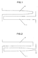
- Figs. 1 and 2 Arrangements of first and second embodiments of the present invention are shown in Figs. 1 and 2, respectively.
- each of upper and lower surfaces of the rotor blade 9 is contoured from the proximal end of the rotor blade 9 to the distal end thereof to present a flexure curve line expressed by Formula 1 or approximately expressed by Formula 1.
- each of upper and lower surfaces of the stator blade 11 is contoured from the distal end of the stator blade 11 to the proximal end thereof to present a flexure curve line expressed by Formula 1 or approximately expressed by Formula 1.
- Fig. 4 shows the flexure amount or deflection of the rotor blade 9, which is obtained by being plotted on the basis of Formula 1. Note that values in Fig. 4 are dimensionless numbers since the entire blade length is assumed to be 1, and the flexure amount at the distal end of the blade is assumed to be 1.
- the clearance between the rotor blade 9 and the stator blade 11 is gradually enlarged from the proximal end of the rotor blade 9 to the distal end of the rotor blade 9 along the flexure curve line based on Formula 1. With this arrangement, it is possible to set the clearance between the rotor blade 9 and the stator blade 11 as small as possible while avoiding the contact between the rotor blade 9 and the stator blade 11.
- the rotor blade 9 side is processed along this flexure curve line
- the stator blade 11 side is processed along this flexure curve line. Note that the former case that the rotor blade 9 side is processed is more advantageous over the latter case from the view point of the reliability since the former case is less flexured.
- FIG. 5 shows an arrangement of the third embodiment of the present invention
- Fig. 6 shows an arrangement of the fourth embodiment of the present invention.
- each of the upper and lower surfaces of the rotor blade 9 is contoured in a three-stepwise manner to present, from the proximal end of the rotor blade 9 to the distal end thereof, a flexure curve line expressed by Formula 1 or approximately expressed by Formula 1.
- Formula 1 a flexure curve line expressed by Formula 1 or approximately expressed by Formula 1.
- each of the upper and lower surfaces of the stator blade 11 is contoured in a three-stepwise manner to present, from the distal end of the stator blade 11 to the proximal end thereof, a flexure curve line expressed by Formula 1 or approximately expressed by Formula 1.
- each of the upper and lower surfaces of the rotor blade 9 or the stator blade 11 is arranged in a stepwise manner to have a plurality of steps as shown in Fig. 5 or 6.
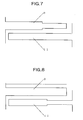
- Fig. 7 shows an arrangement of the fifth embodiment of the present invention
- Fig. 8 shows an arrangement of the sixth embodiment of the present invention.
- each of the upper and lower surfaces of the rotor blade 9 has a single step located at a position 60 % from the proximal end of the rotor blade 9 to the distal end thereof.
- each of the upper and lower surfaces of the stator blade 11 has a single step located at a position 60% from the proximal end of the stator blade 11 to the distal end thereof.
- the turbo molecular pump applies vector momentum to molecule of the gas existing between the rotor blade 9 and the stator blade 11, to thereby convey the molecule of the gas.
- Fig. 9 is polar coordinates showing a space disposed between the blades.
- the exhaust performance of the turbo molecular pump is inferred to have a correlation to the product of the volume of the object surrounded by hatched line in Fig. 9 with its equivalent mean circumferential velocity, which is expressed by Formula 4.
- the character r i denotes a radius of a rotor 1
- the character r 0 denotes a length from a center of the rotor 1 to a distal end of the rotor blade 9.
- the character H denotes a height in the axial direction.
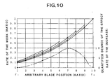
- Fig. 10 shows the work of the rotor blade 9 at an arbitrary position r which is expressed as dimensionless numbers by assuming the work at the distal end of the rotor blade 9 as 1.
- an arbitrary blade position (ratio) is shown as the x-coordinate
- a rate of the work (ratio) is shown as the y-coordinate.
- an optimum clearance 6 at a position at which this step is to be provided is set on the basis of Formula 1.
- the performance in the intermediate flow region at the portion of the clearance ⁇ is enhanced in an inverse-proportional manner.
- a ratio of r i : r 0 is assumed to be 1 : 2.5.
- the calculation is made on the exhaust performance of the turbo molecular pump using Formula 4 on the basis of the clearance obtained from the flexure curve line expressed by Formula 1.
- the four curve lines in Fig. 10, which are respectively extended up to the four points, represent the calculation results.
- the curve line is increased from the (8, 0.68) to (8, 0.75), and thus the exhaust performance is increased.
- the two-dotted chain line in Fig. 10 shows an amount of the increase in the exhaust performance (the amount of the increase is evaluated as an area), which is quantified.
- the degree of this effect is expressed as quantified values on a right-handed side of the graph in the y-axis direction.
- Fig. 11 shows an arrangement of the seventh embodiment of the present invention
- Fig. 12 shows an arrangement of the eighth embodiment of the present invention.
- the curve line processing is applied to the upper and lower surfaces of the rotor blade 9 from a portion of the rotor blade 9.
- the curve line processing is applied to the upper and lower surfaces of the stator blade 11 from a portion of the stator blade 11.
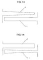
- Fig. 13 shows an arrangement of the ninth embodiment of the present invention
- Fig. 14 shows an arrangement of the tenth embodiment of the present invention.
- a tapered processing is applied to the upper and lower surfaces of the rotor blade 9.
- the tapered processing is applied to the upper and lower surfaces of the stator blade 11.
- Fig. 15 shows an arrangement of the eleventh embodiment of the present invention
- Fig. 16 shows an arrangement of the twelfth embodiment of the present invention.
- the tapered processing is applied to the upper and lower surfaces of the rotor blade 9 from a portion of the rotor blade 9.
- the tapered processing is applied to the upper and lower surfaces of the stator blade 11 from a portion of the stator blade 11.
- Fig. 17 shows an arrangement of the thirteenth embodiment of the present invention.
- the embodiment shown in Fig. 17 is a combination of the fifth embodiment and the sixth embodiment of the present invention. This is not the sole case, and the embodiments described above may be combined in desired manners to form the rotor blade 9 and the stator blade 11.
- Fig. 18 shows an arrangement of the fourteenth embodiment of the present invention.
- three steps are provided only on the lower surface of the rotor blades 9. This is not the sole case, and it goes without saying that a step or steps may be formed only on one of the upper and lower surfaces.
- the arrangement or configuration in each of the seventh to fourteenth embodiments of the present invention can enhance the performance further more in comparison to the related art, and increase the reliability.
- a spatial clearance between the proximal end of a rotor blade and the distal end of a stator blade adjacent thereto is made smaller than a spatial clearance between the distal end of the rotor blade and the proximal end of the stator blade, to thereby enhance the exhaust performance in the case where the flow quantity is large.
Landscapes
- Engineering & Computer Science (AREA)
- Mechanical Engineering (AREA)
- General Engineering & Computer Science (AREA)
- Physics & Mathematics (AREA)
- Geometry (AREA)
- Non-Positive Displacement Air Blowers (AREA)
Applications Claiming Priority (2)
| Application Number | Priority Date | Filing Date | Title |
|---|---|---|---|
| JP17039898 | 1998-06-17 | ||
| JP10170398A JP3092063B2 (ja) | 1998-06-17 | 1998-06-17 | ターボ分子ポンプ |
Publications (2)
| Publication Number | Publication Date |
|---|---|
| EP0965761A2 true EP0965761A2 (de) | 1999-12-22 |
| EP0965761A3 EP0965761A3 (de) | 2001-04-11 |
Family
ID=15904198
Family Applications (1)
| Application Number | Title | Priority Date | Filing Date |
|---|---|---|---|
| EP99304750A Withdrawn EP0965761A3 (de) | 1998-06-17 | 1999-06-17 | Turbomolekularpumpe |
Country Status (3)
| Country | Link |
|---|---|
| US (1) | US6474940B1 (de) |
| EP (1) | EP0965761A3 (de) |
| JP (1) | JP3092063B2 (de) |
Cited By (8)
| Publication number | Priority date | Publication date | Assignee | Title |
|---|---|---|---|---|
| EP1167773A2 (de) | 2000-06-23 | 2002-01-02 | Ebara Corporation | Turbomolekularpumpe |
| EP2757266A1 (de) * | 2013-01-22 | 2014-07-23 | Agilent Technologies, Inc. | Rotationsvakuumpumpe |
| EP3002459A1 (de) * | 2014-10-02 | 2016-04-06 | Pfeiffer Vacuum GmbH | Verfahren zur herstellung einer rotor- oder statorscheibe für eine vakuumpumpe sowie rotor- oder statorscheibe für eine vakuumpumpe |
| EP3091235A1 (de) * | 2015-05-04 | 2016-11-09 | Pfeiffer Vacuum Gmbh | Rotorscheibe |
| EP2019208A4 (de) * | 2006-05-19 | 2017-04-26 | Edwards Japan Limited | Vakuumpumpe |
| GB2552793A (en) * | 2016-08-08 | 2018-02-14 | Edwards Ltd | Vacuum pump |
| EP2341251B1 (de) | 2008-10-03 | 2018-12-26 | Shimadzu Corporation | Turbomolekulare pumpe |
| GB2592618A (en) * | 2020-03-03 | 2021-09-08 | Edwards Ltd | Turbine blades and methods of manufacture of turbine blades |
Families Citing this family (4)
| Publication number | Priority date | Publication date | Assignee | Title |
|---|---|---|---|---|
| JP2005042709A (ja) * | 2003-07-10 | 2005-02-17 | Ebara Corp | 真空ポンプ |
| JP4519185B2 (ja) * | 2008-07-22 | 2010-08-04 | 株式会社大阪真空機器製作所 | ターボ分子ポンプ |
| GB2498816A (en) * | 2012-01-27 | 2013-07-31 | Edwards Ltd | Vacuum pump |
| GB2589151A (en) * | 2019-11-25 | 2021-05-26 | Edwards Ltd | Molecular drag vacuum pump |
Family Cites Families (11)
| Publication number | Priority date | Publication date | Assignee | Title |
|---|---|---|---|---|
| DE433183C (de) * | 1924-05-16 | 1926-08-24 | Erste Bruenner Maschinen Fab | Schaufeln fuer achsiale Dampf- oder Gasturbinen |
| US2991929A (en) * | 1955-05-12 | 1961-07-11 | Stalker Corp | Supersonic compressors |
| BE757354A (fr) * | 1969-10-27 | 1971-03-16 | Sargent Welch Scientific Co | Pompe turbomoleculaire a stators et rotors perfectionnes |
| DE2229724B2 (de) * | 1972-06-19 | 1980-06-04 | Leybold-Heraeus Gmbh, 5000 Koeln | Turbomolekularpumpe |
| DE2923632A1 (de) | 1979-06-11 | 1980-12-18 | Leybold Heraeus Gmbh & Co Kg | Verfahren zur herstellung eines schaufelkranzes fuer den rotor einer tubomolekularpumpe und mit schaufelkraenzen dieser art ausgeruesteter rotor |
| JPH0261387A (ja) * | 1988-08-24 | 1990-03-01 | Seiko Seiki Co Ltd | ターボ分子ポンプ |
| DE4216237A1 (de) * | 1992-05-16 | 1993-11-18 | Leybold Ag | Gasreibungsvakuumpumpe |
| GB9318801D0 (en) * | 1993-09-10 | 1993-10-27 | Boc Group Plc | Improved vacuum pumps |
| JPH1089284A (ja) | 1996-09-12 | 1998-04-07 | Seiko Seiki Co Ltd | ターボ分子ポンプ |
| JPH10246195A (ja) | 1997-03-05 | 1998-09-14 | Ebara Corp | ターボ分子ポンプ |
| DE29715035U1 (de) | 1997-08-22 | 1997-10-30 | Leybold Vakuum GmbH, 50968 Köln | Reibungsvakuumpumpe |
-
1998
- 1998-06-17 JP JP10170398A patent/JP3092063B2/ja not_active Expired - Fee Related
-
1999
- 1999-06-16 US US09/334,308 patent/US6474940B1/en not_active Expired - Fee Related
- 1999-06-17 EP EP99304750A patent/EP0965761A3/de not_active Withdrawn
Cited By (16)
| Publication number | Priority date | Publication date | Assignee | Title |
|---|---|---|---|---|
| EP1167773A3 (de) * | 2000-06-23 | 2002-02-27 | Ebara Corporation | Turbomolekulapumpe |
| US6468030B2 (en) | 2000-06-23 | 2002-10-22 | Ebara Corporation | Turbo-molecular pump |
| EP2053250A3 (de) * | 2000-06-23 | 2009-07-15 | Ebara Corporation | Turbomolekularpumpe |
| EP2284400A1 (de) * | 2000-06-23 | 2011-02-16 | Ebara Corporation | Turbomolekularpumpe |
| EP1167773A2 (de) | 2000-06-23 | 2002-01-02 | Ebara Corporation | Turbomolekularpumpe |
| EP2019208A4 (de) * | 2006-05-19 | 2017-04-26 | Edwards Japan Limited | Vakuumpumpe |
| EP2341251B1 (de) | 2008-10-03 | 2018-12-26 | Shimadzu Corporation | Turbomolekulare pumpe |
| EP2757266A1 (de) * | 2013-01-22 | 2014-07-23 | Agilent Technologies, Inc. | Rotationsvakuumpumpe |
| CN103939367A (zh) * | 2013-01-22 | 2014-07-23 | 安捷伦科技有限公司 | 旋转真空泵 |
| US9670931B2 (en) | 2013-01-22 | 2017-06-06 | Agilent Technologies Inc. | Rotary vacuum pump |
| CN103939367B (zh) * | 2013-01-22 | 2017-11-17 | 安捷伦科技有限公司 | 旋转真空泵 |
| EP3002459A1 (de) * | 2014-10-02 | 2016-04-06 | Pfeiffer Vacuum GmbH | Verfahren zur herstellung einer rotor- oder statorscheibe für eine vakuumpumpe sowie rotor- oder statorscheibe für eine vakuumpumpe |
| EP3091235A1 (de) * | 2015-05-04 | 2016-11-09 | Pfeiffer Vacuum Gmbh | Rotorscheibe |
| GB2552793A (en) * | 2016-08-08 | 2018-02-14 | Edwards Ltd | Vacuum pump |
| US10844864B2 (en) | 2016-08-08 | 2020-11-24 | Edwards Limited | Vacuum pump |
| GB2592618A (en) * | 2020-03-03 | 2021-09-08 | Edwards Ltd | Turbine blades and methods of manufacture of turbine blades |
Also Published As
| Publication number | Publication date |
|---|---|
| EP0965761A3 (de) | 2001-04-11 |
| JP2000009086A (ja) | 2000-01-11 |
| JP3092063B2 (ja) | 2000-09-25 |
| US6474940B1 (en) | 2002-11-05 |
Similar Documents
| Publication | Publication Date | Title |
|---|---|---|
| EP0965761A2 (de) | Turbomolekularpumpe | |
| US8070428B2 (en) | Airfoil shape for a turbine nozzle | |
| KR100730840B1 (ko) | 원심 압축기 및 임펠러의 제조 방법 | |
| US7517188B2 (en) | Airfoil shape for a compressor | |
| US7517196B2 (en) | Airfoil shape for a compressor | |
| US8882456B2 (en) | Airfoil shape for compressor | |
| JP2008106775A (ja) | タービンノズル用の翼形部形状 | |
| JP2008106750A (ja) | 圧縮機用の翼形状 | |
| JP2001055996A (ja) | ロータブレード | |
| JP2008106762A (ja) | 圧縮機用の翼形状 | |
| JP2636356B2 (ja) | 分子ポンプ | |
| JPH04279701A (ja) | ターボエンジン用翼列及びかかる翼列を有するターボエンジン | |
| US20170306971A1 (en) | Impeller, centrifugal fluid machine, and fluid device | |
| EP1327749A1 (de) | Turbine mit veränderlichem schluckvermögen | |
| US7118330B2 (en) | Turbine nozzle airfoil | |
| KR20000035609A (ko) | 터보 분자 펌프 및 진공장치 | |
| JP3957761B2 (ja) | 摩擦真空ポンプ | |
| JP2000283086A5 (de) | ||
| EP1041287A3 (de) | Vakuumpumpe | |
| US8038409B2 (en) | Turbomachine with rotors of high specific energy transfer | |
| US11732722B2 (en) | Vacuum pump | |
| KR20030032046A (ko) | 회전자 블레이드 열 및 고정자 블레이드 열을 갖는 터보분자 진공 펌프 | |
| KR20060021120A (ko) | 송풍기용 스크롤 하우징 | |
| JP3532653B2 (ja) | ターボ分子ポンプ | |
| JP2003120591A (ja) | ターボ機械 |
Legal Events
| Date | Code | Title | Description |
|---|---|---|---|
| PUAI | Public reference made under article 153(3) epc to a published international application that has entered the european phase |
Free format text: ORIGINAL CODE: 0009012 |
|
| AK | Designated contracting states |
Kind code of ref document: A2 Designated state(s): DE FR GB |
|
| AX | Request for extension of the european patent |
Free format text: AL;LT;LV;MK;RO;SI |
|
| PUAL | Search report despatched |
Free format text: ORIGINAL CODE: 0009013 |
|
| AK | Designated contracting states |
Kind code of ref document: A3 Designated state(s): AT BE CH CY DE DK ES FI FR GB GR IE IT LI LU MC NL PT SE |
|
| AX | Request for extension of the european patent |
Free format text: AL;LT;LV;MK;RO;SI |
|
| 17P | Request for examination filed |
Effective date: 20010913 |
|
| AKX | Designation fees paid |
Free format text: DE FR GB |
|
| RAP1 | Party data changed (applicant data changed or rights of an application transferred) |
Owner name: SEIKO INSTRUMENTS INC. |
|
| STAA | Information on the status of an ep patent application or granted ep patent |
Free format text: STATUS: THE APPLICATION IS DEEMED TO BE WITHDRAWN |
|
| 18D | Application deemed to be withdrawn |
Effective date: 20040103 |