EP0965768A1 - Spannmutter - Google Patents
Spannmutter Download PDFInfo
- Publication number
- EP0965768A1 EP0965768A1 EP99810505A EP99810505A EP0965768A1 EP 0965768 A1 EP0965768 A1 EP 0965768A1 EP 99810505 A EP99810505 A EP 99810505A EP 99810505 A EP99810505 A EP 99810505A EP 0965768 A1 EP0965768 A1 EP 0965768A1
- Authority
- EP
- European Patent Office
- Prior art keywords
- clamping elements
- nut
- clamping
- nut according
- thread
- Prior art date
- Legal status (The legal status is an assumption and is not a legal conclusion. Google has not performed a legal analysis and makes no representation as to the accuracy of the status listed.)
- Granted
Links
- 238000007789 sealing Methods 0.000 claims description 11
- 230000002093 peripheral effect Effects 0.000 claims description 3
- 239000007787 solid Substances 0.000 claims description 3
- 230000018109 developmental process Effects 0.000 description 3
- 230000000903 blocking effect Effects 0.000 description 2
- 238000004519 manufacturing process Methods 0.000 description 2
- 230000011218 segmentation Effects 0.000 description 2
- CWYNVVGOOAEACU-UHFFFAOYSA-N Fe2+ Chemical compound [Fe+2] CWYNVVGOOAEACU-UHFFFAOYSA-N 0.000 description 1
- 210000000078 claw Anatomy 0.000 description 1
- 230000008878 coupling Effects 0.000 description 1
- 238000010168 coupling process Methods 0.000 description 1
- 238000005859 coupling reaction Methods 0.000 description 1
- 230000001419 dependent effect Effects 0.000 description 1
- 239000003292 glue Substances 0.000 description 1
- 239000002184 metal Substances 0.000 description 1
- 230000036316 preload Effects 0.000 description 1
Images

Classifications
-
- F—MECHANICAL ENGINEERING; LIGHTING; HEATING; WEAPONS; BLASTING
- F16—ENGINEERING ELEMENTS AND UNITS; GENERAL MEASURES FOR PRODUCING AND MAINTAINING EFFECTIVE FUNCTIONING OF MACHINES OR INSTALLATIONS; THERMAL INSULATION IN GENERAL
- F16B—DEVICES FOR FASTENING OR SECURING CONSTRUCTIONAL ELEMENTS OR MACHINE PARTS TOGETHER, e.g. NAILS, BOLTS, CIRCLIPS, CLAMPS, CLIPS OR WEDGES; JOINTS OR JOINTING
- F16B39/00—Locking of screws, bolts or nuts
- F16B39/02—Locking of screws, bolts or nuts in which the locking takes place after screwing down
- F16B39/028—Locking of screws, bolts or nuts in which the locking takes place after screwing down by means of an auxiliary bolt or threaded element whose action provokes the deformation of the main bolt or nut and thereby its blocking
-
- F—MECHANICAL ENGINEERING; LIGHTING; HEATING; WEAPONS; BLASTING
- F16—ENGINEERING ELEMENTS AND UNITS; GENERAL MEASURES FOR PRODUCING AND MAINTAINING EFFECTIVE FUNCTIONING OF MACHINES OR INSTALLATIONS; THERMAL INSULATION IN GENERAL
- F16C—SHAFTS; FLEXIBLE SHAFTS; ELEMENTS OR CRANKSHAFT MECHANISMS; ROTARY BODIES OTHER THAN GEARING ELEMENTS; BEARINGS
- F16C19/00—Bearings with rolling contact, for exclusively rotary movement
- F16C19/54—Systems consisting of a plurality of bearings with rolling friction
Definitions
- the invention relates to a precision clamping nut, with a massive nut block, which has an internal thread, a machined and aligned at right angles to the axis of the thread Has end face and a peripheral surface, with clamping elements, each a radially extending and segment-shaped Form part of a part of the nut block and for axial securing by means of an axially parallel one Clamping screw are resiliently tiltable.
- Precision clamping nuts of this type are, for example, from the SU-A-1 375 873, FR-A-668 722 and EP-A-0 609 286 become. Such precision locknuts are against one Loosened secured and consist essentially of a solid Nut block.
- Nuts with clamping and locking devices are in a wide variety Designs known. The main distinction is made those with radial locking and those with axial Blocking. Through different manufacturing processes on one high accuracy of the thread in relation to the axial runout End face value. It is also required that the breakaway torques should be a multiple of the tightening torque. These requirements can be met with the standard designs radial locking systems can be achieved. Have these nuts usually two or more radial mounting plugs that are partly made of non-ferrous metal and at the same time with the Mother to be edited. These locking plugs are made after by tightening the nuts with the desired torque Blocked screws against the thread and reach one high degree of safety related to the breakaway torque. In many However, for technical reasons, radial locking is required not possible. To achieve an axial securing, the securing elements must be operated axially parallel. For this there are essentially two systems, but both with significant Disadvantages are connected.
- the securing is like the radial securing system by means of plugs acting radially on the thread.
- a 90 ° deflection is necessary in order to arrange the tightening screws axially parallel.
- the 90 ° deflection now usually happens through two systems, either have the axial tightening screws and the plug have a conical surface, which should transmit the power or there are versions, who have an eccentric clamp. Both versions are but unable to apply the necessary forces, to achieve the required breakaway torques. With unfavorable The breakaway element can tolerate the same as the tightening element be. As a result, in practice, aids, such as glue are required. In this case then usually all the effort for the security system useless.
- the second system uses the principle of axial bracing worked. This principle also applies to other technical components, for example in couplings, known and per se effective.
- the desired rigid nut block with a certain elasticity be provided. This happens in many forms. Nuts with recesses in radial form in the inner diameter or in Outside diameter or inside and outside diameter customary in the market. To achieve further elasticity, too in addition to radial recesses, segmentations performed. These segmentations are said to be clamping ability enlarge. Precision locknuts based on this second system have in common that they each cover the entire radial circumference the mother always in some form against the basic block be tense.
- the invention has for its object a precision clamping nut to create the genus mentioned, which the above avoids disadvantages mentioned.
- the precision clamping nut according to the invention should therefore a delay of the plan area and that Loosen by insufficient securing to a greater extent than hitherto prevented and it should also be produced inexpensively can be.
- the task is solved with a precision clamping nut that the clamping elements form at most 50% of the named part, in such a way that when axially securing on the clamping side at most 50% of the thread circumference in the originally manufactured Shape to be changed.
- the precision clamping nut according to the invention consists essentially of a base nut block. Also on the clamping side are not with axial locking more than 50% of the original block and thread in the original manufactured shape changed. would the clamping parts remove, the mother would be contrary to the prior art still functional over the entire length. In the active Clamping zone are thus from the original solid base block more than 50% unchanged.
- clamping elements there is an even number provided by clamping elements and seen in the circumferential direction these clamping elements are alternately in opposite axial Directions tilted.
- the clamping elements are then designed that a clamping element repels on the base block and the other gets dressed. The forces then lift each other on. There is a clawing of the clamping elements mutually in the thread, so that almost no internal forces transferred to the original nut block. It deals then a real blocking system and not the Jamming of two female parts, as with the common ones Executions.
- the clamping elements are tilted in a particularly suitable manner Way in that the clamping elements alternate with a Pressure or lag screw are provided.
- the part mentioned is in Arranged inside the mother.
- These clamping elements are preferred through two machined into the nut body radial inner grooves formed.
- the division of the tiltable Cutouts are preferably made through radial bores. This makes production particularly simple and inexpensive guaranteed.
- the clamping nut has one radial outer groove in which a sealing ring, preferably a labyrinth seal is used.
- a sealing ring preferably a labyrinth seal is used.
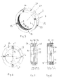
- the precision clamping nut shown in Figure 1 approximately in natural size 1 has a nut block 3 which has a bore 5 has an internal thread 7.
- a circumferential radial inner groove 9 divides the nut block 3 into a basic block 3a and a part 3b ( Figure 3).
- Part 3b is through radial grooves 11 and 10a divided into sections 12, 13 and 16. These sections are each with comparatively narrow webs 18 the base block 3a connected resiliently.
- the thread 7 is in an area 7a of the base block 3a and an area 7b of sections 12, 13 and 16. The subdivision occurs when the groove 9 is incorporated.
- the sections 12 each have a continuous center Threaded bore 29 into which a pressure screw 14 is inserted.
- These pressure screws 14 are with a suitable Allen key can be operated axially from the front 22 and lie according to FIG. 4 with an end face 14 'on a surface 30 of the groove 9.
- the pressure screws 14 becomes the respective section 12 repelled from the base block 3a and slightly around the web 18 tilted outwards.
- the threaded parts 7b of the sections 12 are thus on the external thread not shown here, for example jammed by a threaded spindle, such that the Locknut 1 can no longer be rotated.
- the sections 13 are also in the center with a Provide stepped bore 32 into which a lag screw 15 is inserted is which with its shaft in a threaded bore 31 of the Basic body 13 engages.
- a lag screw 15 When tightening the lag screws 15 the corresponding section 13 around the web 18 becomes the basic body 3a tilted out.
- the tilting motion is also axial, however opposite to that of the elements 12.
- jamming of the threaded area 7b with the external thread for example a threaded spindle instead.
- Sections 12 and 13 thus form clamping elements that can be operated from the front 22 are. As FIGS. 1 and 2 show, the same clamping elements are located 12 or 13 diametrically opposite.
- the arrangement of the clamping elements is preferably symmetrical and preferably is one Even number of clamping elements 12 and 13 is provided.
- the sections 12 and 13 claw each other in the thread, making it so good how no forces are transferred to the base block 3a.
- a total of four clamping elements 12 and 13 are provided.
- a version is also conceivable in which more, for example ten clamping elements are provided.
- a circumferential radial groove 19 can be machined into the peripheral surface 17 be in which a sealing ring 19, preferably a lamellar sealing ring is inserted.
- the clamping nut 1 forms then a precision sealing nut with the lamellar sealing ring 19 in the outer diameter of the surrounding, not shown here Can center the housing.
- the sealing ring 19 'or the groove 19 can also be omitted.
- the above considerations also apply to the precision clamping nut 2 shown in FIGS. 5 to 8.
- This also has a nut block 4, which is cylindrical Has outer surface 21.
- the outer surface 21 can, however also polygonal, for example hexagonal.
- To put on the A plurality of grooves 28 are machined into the outer surface 21 of the clamping nut 2.
- the high-precision ground plane surface 23 is located 7 in relation to the front side 22, from which two pressure screws 14 and two tension screws 15 can be operated are.
- the tiltable sections 14b are located here inside the nut body 4 and is through two raidial grooves 34 and 35 formed, as Figures 7 and 8 clearly show.
- sections 36 Two opposite According to FIG. 8, sections 36 have a threaded bore 26, into which a lag screw 15 is screwed. On a pressure screw 14 is located in the other two sections 36 ' on, which is screwed into a threaded bore 27 of part 4c. With the screws 15 and 14, the sections 36 and 36 ' lift or pressure loaded and thus in the opposite direction tilted. The clawing mentioned above is also here of the loaded sections guaranteed. On the sections 4a and 4c of the nut block 4 become almost no internal Transfer forces.
Landscapes
- Engineering & Computer Science (AREA)
- General Engineering & Computer Science (AREA)
- Mechanical Engineering (AREA)
- Clamps And Clips (AREA)
- Buildings Adapted To Withstand Abnormal External Influences (AREA)
- Investigating Or Analyzing Materials By The Use Of Ultrasonic Waves (AREA)
- Diaphragms For Electromechanical Transducers (AREA)
- Financial Or Insurance-Related Operations Such As Payment And Settlement (AREA)
- Transmission Devices (AREA)
Abstract
Description
Claims (10)
- Präzisions-Spannmutter, mit einem massiven Mutternblock (2, 3), der ein Innengewinde (7, 8), eine planbearbeitete und im rechten Winkel zur Achse des Gewindes (7, 8) ausgerichtete Stirnfläche (23) sowie eine Umfangsfläche (17, 21) aufweist, mit Klemmelementen (12, 13; 36, 36'), die jeweils einen sich radial erstreckenden und segementförmigen Ausschnitt aus einem Teil des Mutternblockes (3, 4) bilden und zur axialen Sicherung mittels einer achsparallel bedienbaren Klemmschraube (14, 15) federnd kippbar sind, dadurch gekennzeichnet, dass die Klemmelemente (12, 13; 36, 36') höchstens 50 % des genannten Teils (3b; 4b, 4c) bildet, derart, dass beim axialen Sichern auf der Spannseite höchstens 50 % des Gewindeumfangs in der ursprünglich gefertigten Form verändert werden.
- Mutter nach Anspruch 1, dadurch gekennzeichnet, dass eine gerade Anzahl von Klemmelementen (12, 13; 36, 36') vorgesehen ist und dass in Umfangsrichtung gesehen diese Klemmelemente abwechselnd in entgegengesetzte axiale Richtungen verkippbar sind.
- Mutter nach Anspruch 2, dadurch gekennzeichnet, dass die Klemmelemente (12, 13; 36, 36') abwechselnd mit einer Druck- oder Zugschraube (14, 15) versehen sind.
- Mutter nach einem der Ansprüche 1 bis 3, dadurch gekennzeichnet, dass jeweils zwischen zwei Klemmelementen (12, 13) ein segmentförmiger und nicht spannbarer Abschnitt (16) des Mutternkörpers (3) angeordnet ist.
- Mutter nach Anspruch 4, dadurch gekennzeichnet, dass die nicht spannbaren Abschnitte (16) in Umfangsrichtung gesehen jeweils kürzer sind als die spannbaren Klemmelemente (12, 13).
- Mutter nach Anspruch 4 oder 5, dadurch gekennzeichnet, dass vier Klemmelemente (12, 13) und vier nicht spannbare Abschnitte (16) vorgesehen sind.
- Mutter nach einem der Ansprüche 1 bis 6, dadurch gekennzeichnet, dass die Klemmelemente (36, 36') im Innern des Mutternkörpers (4) angeordnet sind und diese Klemmelemente (36, 36') eine Dicke aufweisen, die wesentlich kleiner, vorzugsweise höchstens 50 % der Dicke eines äusseren Bereichs (4c) aufweist.
- Mutter nach Anspruch 7, dadurch gekennzeichnet, dass die Klemmelemente (36, 36') durch zwei innenseitig in den Mutternkörper (4) eingearbeitete Innennuten (34, 35) gebildet sind.
- Mutter nach Anspruch 7 oder 8, dadurch gekennzeichnet, dass die Klemmelemente (36, 36') durch radiale Bohrungen (25) unterteilt sind.
- Mutter nach einem der Ansprüche 1 bis 9, dadurch gekennzeichnet, dass sie eine radiale Aussennut (19') aufweist, in welche ein Dichtring (19), vorzugsweise ein Labyrinthdichtring eingesetzt ist.
Applications Claiming Priority (2)
| Application Number | Priority Date | Filing Date | Title |
|---|---|---|---|
| CH130098 | 1998-06-16 | ||
| CH130098 | 1998-06-16 |
Publications (2)
| Publication Number | Publication Date |
|---|---|
| EP0965768A1 true EP0965768A1 (de) | 1999-12-22 |
| EP0965768B1 EP0965768B1 (de) | 2002-09-25 |
Family
ID=4207221
Family Applications (1)
| Application Number | Title | Priority Date | Filing Date |
|---|---|---|---|
| EP99810505A Expired - Lifetime EP0965768B1 (de) | 1998-06-16 | 1999-06-09 | Spannmutter |
Country Status (4)
| Country | Link |
|---|---|
| EP (1) | EP0965768B1 (de) |
| AT (1) | ATE225004T1 (de) |
| DE (1) | DE59902815D1 (de) |
| ES (1) | ES2183498T3 (de) |
Cited By (5)
| Publication number | Priority date | Publication date | Assignee | Title |
|---|---|---|---|---|
| DE10252780A1 (de) * | 2002-11-07 | 2004-05-27 | Spieth-Maschinenelemente Gmbh & Co Kg | Gewindering |
| WO2005073570A1 (de) * | 2004-01-22 | 2005-08-11 | Spieth-Maschinenelemente Gmbh & Co. Kg | Gewindering |
| CN102562760A (zh) * | 2010-12-17 | 2012-07-11 | 盈锡精密工业股份有限公司 | 复合锁制的精密螺帽 |
| EP2463530A3 (de) * | 2010-12-09 | 2012-08-22 | Yinsh Precision Ind. Co., Ltd. | Präzisionssicherungsmutter mit mehreren Verriegelungsmechanismusmodi |
| DE102017219848A1 (de) | 2017-11-08 | 2019-05-09 | Robert Bosch Gmbh | Gewindespindel |
Citations (4)
| Publication number | Priority date | Publication date | Assignee | Title |
|---|---|---|---|---|
| DE3020521A1 (de) * | 1980-05-30 | 1981-12-03 | Emuge-Werk Richard Glimpel Fabrik für Präzisionswerkzeuge vormals Moschkau & Glimpel, 8560 Lauf | Spannmutter |
| DE3917758A1 (de) * | 1988-06-02 | 1989-12-07 | Ingersoll Rand Co | Verriegelbare mutter |
| US5540529A (en) * | 1991-10-02 | 1996-07-30 | Ina Walzlager Schaeffler Kg | Locking member |
| FR2743121A1 (fr) * | 1995-12-29 | 1997-07-04 | Sfero | Organe filete d'assemblage |
-
1999
- 1999-06-09 AT AT99810505T patent/ATE225004T1/de not_active IP Right Cessation
- 1999-06-09 ES ES99810505T patent/ES2183498T3/es not_active Expired - Lifetime
- 1999-06-09 DE DE59902815T patent/DE59902815D1/de not_active Expired - Lifetime
- 1999-06-09 EP EP99810505A patent/EP0965768B1/de not_active Expired - Lifetime
Patent Citations (4)
| Publication number | Priority date | Publication date | Assignee | Title |
|---|---|---|---|---|
| DE3020521A1 (de) * | 1980-05-30 | 1981-12-03 | Emuge-Werk Richard Glimpel Fabrik für Präzisionswerkzeuge vormals Moschkau & Glimpel, 8560 Lauf | Spannmutter |
| DE3917758A1 (de) * | 1988-06-02 | 1989-12-07 | Ingersoll Rand Co | Verriegelbare mutter |
| US5540529A (en) * | 1991-10-02 | 1996-07-30 | Ina Walzlager Schaeffler Kg | Locking member |
| FR2743121A1 (fr) * | 1995-12-29 | 1997-07-04 | Sfero | Organe filete d'assemblage |
Cited By (10)
| Publication number | Priority date | Publication date | Assignee | Title |
|---|---|---|---|---|
| DE10252780A1 (de) * | 2002-11-07 | 2004-05-27 | Spieth-Maschinenelemente Gmbh & Co Kg | Gewindering |
| DE10252780B4 (de) * | 2002-11-07 | 2004-09-30 | Spieth-Maschinenelemente Gmbh & Co Kg | Gewindering |
| JP2006519337A (ja) * | 2002-11-07 | 2006-08-24 | スピース−マシーネンエレメンテ ゲゼルシャフト ミット ベシュレンクテル ハフツング ウント コンパニー コマンディトゲゼルシャフト | ねじリング |
| WO2005073570A1 (de) * | 2004-01-22 | 2005-08-11 | Spieth-Maschinenelemente Gmbh & Co. Kg | Gewindering |
| CN100408871C (zh) * | 2004-01-22 | 2008-08-06 | 斯比特机械部件有限及两合公司 | 螺纹环 |
| US7600958B2 (en) | 2004-01-22 | 2009-10-13 | Speith-Maschinenelemente GmbH & Co. KG | Threaded ring |
| EP2463530A3 (de) * | 2010-12-09 | 2012-08-22 | Yinsh Precision Ind. Co., Ltd. | Präzisionssicherungsmutter mit mehreren Verriegelungsmechanismusmodi |
| CN102562760A (zh) * | 2010-12-17 | 2012-07-11 | 盈锡精密工业股份有限公司 | 复合锁制的精密螺帽 |
| CN102562760B (zh) * | 2010-12-17 | 2014-11-12 | 盈锡精密工业股份有限公司 | 复合锁制的精密螺帽 |
| DE102017219848A1 (de) | 2017-11-08 | 2019-05-09 | Robert Bosch Gmbh | Gewindespindel |
Also Published As
| Publication number | Publication date |
|---|---|
| ES2183498T3 (es) | 2003-03-16 |
| EP0965768B1 (de) | 2002-09-25 |
| ATE225004T1 (de) | 2002-10-15 |
| DE59902815D1 (de) | 2002-10-31 |
Similar Documents
| Publication | Publication Date | Title |
|---|---|---|
| DE69700671T2 (de) | Sicherungsmutter | |
| EP0370212B1 (de) | Mutter mit Druckring | |
| DE102007012487B4 (de) | Werkzeughalter | |
| EP0385280B1 (de) | Innendrehmeissel | |
| DE60319305T2 (de) | Kupplungsvorrichtung für Schneidwerkzeughalter | |
| DE102010014322B4 (de) | Werkzeugkopf für ein rotierendes Werkzeug | |
| DE4208548A1 (de) | Steckschluesselmaul | |
| EP2511539A1 (de) | Schraubverbindung | |
| EP0500746B1 (de) | Konusspannsatz | |
| DE3546671C2 (de) | ||
| EP1706654B1 (de) | Gewindering | |
| EP0965768B1 (de) | Spannmutter | |
| EP1312810B1 (de) | Kolben/Zylinder-Einheit mit einer Drehsicherung zwichen Kolben und Kolbenstange | |
| DE69226782T2 (de) | Verriegelungsglied | |
| DE69426825T2 (de) | Arretiervorrichtung zur verwendung auf wellen oder in röhren | |
| DE8806205U1 (de) | Formschlüssig arbeitende kraftbegrenzende Kupplung | |
| DE2609186A1 (de) | Sicherheitsmutter | |
| DE3204919C1 (de) | Kugelgewindetrieb | |
| DE3020521A1 (de) | Spannmutter | |
| DE10162910B4 (de) | Klemmspaltmutter | |
| CH716094B1 (de) | Winkelversetzte Schraubeneingriffnahme. | |
| EP3289232B1 (de) | Spannmutter | |
| DE202013006947U1 (de) | Mutter mit integrierter Sicherung | |
| EP0598289B1 (de) | Bolzenförmiges Passelement zum Fixieren, Zentrieren und/oder Positionieren von Passbohrungen aufweisenden Teilen | |
| EP1316737B1 (de) | Klemmring |
Legal Events
| Date | Code | Title | Description |
|---|---|---|---|
| PUAI | Public reference made under article 153(3) epc to a published international application that has entered the european phase |
Free format text: ORIGINAL CODE: 0009012 |
|
| AK | Designated contracting states |
Kind code of ref document: A1 Designated state(s): AT BE CH DE ES FR GB IT LI SE |
|
| AX | Request for extension of the european patent |
Free format text: AL;LT;LV;MK;RO;SI |
|
| 17P | Request for examination filed |
Effective date: 20000526 |
|
| AKX | Designation fees paid |
Free format text: AT BE CH DE ES FR GB IT LI SE |
|
| 17Q | First examination report despatched |
Effective date: 20010124 |
|
| GRAG | Despatch of communication of intention to grant |
Free format text: ORIGINAL CODE: EPIDOS AGRA |
|
| GRAG | Despatch of communication of intention to grant |
Free format text: ORIGINAL CODE: EPIDOS AGRA |
|
| GRAH | Despatch of communication of intention to grant a patent |
Free format text: ORIGINAL CODE: EPIDOS IGRA |
|
| GRAH | Despatch of communication of intention to grant a patent |
Free format text: ORIGINAL CODE: EPIDOS IGRA |
|
| GRAA | (expected) grant |
Free format text: ORIGINAL CODE: 0009210 |
|
| AK | Designated contracting states |
Kind code of ref document: B1 Designated state(s): AT BE CH DE ES FR GB IT LI SE |
|
| REF | Corresponds to: |
Ref document number: 225004 Country of ref document: AT Date of ref document: 20021015 Kind code of ref document: T |
|
| REG | Reference to a national code |
Ref country code: GB Ref legal event code: FG4D Free format text: NOT ENGLISH |
|
| REG | Reference to a national code |
Ref country code: CH Ref legal event code: EP |
|
| REG | Reference to a national code |
Ref country code: CH Ref legal event code: NV Representative=s name: ISLER & PEDRAZZINI AG |
|
| REF | Corresponds to: |
Ref document number: 59902815 Country of ref document: DE Date of ref document: 20021031 |
|
| PG25 | Lapsed in a contracting state [announced via postgrant information from national office to epo] |
Ref country code: SE Free format text: LAPSE BECAUSE OF FAILURE TO SUBMIT A TRANSLATION OF THE DESCRIPTION OR TO PAY THE FEE WITHIN THE PRESCRIBED TIME-LIMIT Effective date: 20021225 |
|
| GBT | Gb: translation of ep patent filed (gb section 77(6)(a)/1977) |
Effective date: 20030122 |
|
| ET | Fr: translation filed | ||
| REG | Reference to a national code |
Ref country code: ES Ref legal event code: FG2A Ref document number: 2183498 Country of ref document: ES Kind code of ref document: T3 |
|
| PG25 | Lapsed in a contracting state [announced via postgrant information from national office to epo] |
Ref country code: BE Free format text: LAPSE BECAUSE OF NON-PAYMENT OF DUE FEES Effective date: 20030630 |
|
| PLBE | No opposition filed within time limit |
Free format text: ORIGINAL CODE: 0009261 |
|
| STAA | Information on the status of an ep patent application or granted ep patent |
Free format text: STATUS: NO OPPOSITION FILED WITHIN TIME LIMIT |
|
| 26N | No opposition filed |
Effective date: 20030626 |
|
| BERE | Be: lapsed |
Owner name: INDUSTRIAL BEARINGS + COMPONENTS A.G. *IBC Effective date: 20030630 |
|
| PGFP | Annual fee paid to national office [announced via postgrant information from national office to epo] |
Ref country code: FR Payment date: 20050512 Year of fee payment: 7 |
|
| PGFP | Annual fee paid to national office [announced via postgrant information from national office to epo] |
Ref country code: GB Payment date: 20050516 Year of fee payment: 7 |
|
| PGFP | Annual fee paid to national office [announced via postgrant information from national office to epo] |
Ref country code: AT Payment date: 20060608 Year of fee payment: 8 |
|
| PG25 | Lapsed in a contracting state [announced via postgrant information from national office to epo] |
Ref country code: GB Free format text: LAPSE BECAUSE OF NON-PAYMENT OF DUE FEES Effective date: 20060609 |
|
| PGFP | Annual fee paid to national office [announced via postgrant information from national office to epo] |
Ref country code: ES Payment date: 20060706 Year of fee payment: 8 |
|
| GBPC | Gb: european patent ceased through non-payment of renewal fee |
Effective date: 20060609 |
|
| REG | Reference to a national code |
Ref country code: FR Ref legal event code: ST Effective date: 20070228 |
|
| REG | Reference to a national code |
Ref country code: CH Ref legal event code: PCAR Free format text: ISLER & PEDRAZZINI AG;POSTFACH 1772;8027 ZUERICH (CH) |
|
| PG25 | Lapsed in a contracting state [announced via postgrant information from national office to epo] |
Ref country code: AT Free format text: LAPSE BECAUSE OF NON-PAYMENT OF DUE FEES Effective date: 20070609 |
|
| PG25 | Lapsed in a contracting state [announced via postgrant information from national office to epo] |
Ref country code: FR Free format text: LAPSE BECAUSE OF NON-PAYMENT OF DUE FEES Effective date: 20060630 |
|
| REG | Reference to a national code |
Ref country code: ES Ref legal event code: FD2A Effective date: 20070611 |
|
| PG25 | Lapsed in a contracting state [announced via postgrant information from national office to epo] |
Ref country code: ES Free format text: LAPSE BECAUSE OF NON-PAYMENT OF DUE FEES Effective date: 20070611 |
|
| PGFP | Annual fee paid to national office [announced via postgrant information from national office to epo] |
Ref country code: CH Payment date: 20180611 Year of fee payment: 20 Ref country code: DE Payment date: 20180625 Year of fee payment: 20 |
|
| PGFP | Annual fee paid to national office [announced via postgrant information from national office to epo] |
Ref country code: IT Payment date: 20180622 Year of fee payment: 20 |
|
| REG | Reference to a national code |
Ref country code: DE Ref legal event code: R071 Ref document number: 59902815 Country of ref document: DE |
|
| REG | Reference to a national code |
Ref country code: CH Ref legal event code: PL |