EP0965769A1 - Gesinterter Synchronring - Google Patents
Gesinterter Synchronring Download PDFInfo
- Publication number
- EP0965769A1 EP0965769A1 EP99410078A EP99410078A EP0965769A1 EP 0965769 A1 EP0965769 A1 EP 0965769A1 EP 99410078 A EP99410078 A EP 99410078A EP 99410078 A EP99410078 A EP 99410078A EP 0965769 A1 EP0965769 A1 EP 0965769A1
- Authority
- EP
- European Patent Office
- Prior art keywords
- teeth
- ring
- synchronization
- synchronization ring
- sintered
- Prior art date
- Legal status (The legal status is an assumption and is not a legal conclusion. Google has not performed a legal analysis and makes no representation as to the accuracy of the status listed.)
- Withdrawn
Links
Images
Classifications
-
- F—MECHANICAL ENGINEERING; LIGHTING; HEATING; WEAPONS; BLASTING
- F16—ENGINEERING ELEMENTS AND UNITS; GENERAL MEASURES FOR PRODUCING AND MAINTAINING EFFECTIVE FUNCTIONING OF MACHINES OR INSTALLATIONS; THERMAL INSULATION IN GENERAL
- F16D—COUPLINGS FOR TRANSMITTING ROTATION; CLUTCHES; BRAKES
- F16D23/00—Details of mechanically-actuated clutches not specific for one distinct type
- F16D23/02—Arrangements for synchronisation, also for power-operated clutches
- F16D23/04—Arrangements for synchronisation, also for power-operated clutches with an additional friction clutch
-
- F—MECHANICAL ENGINEERING; LIGHTING; HEATING; WEAPONS; BLASTING
- F16—ENGINEERING ELEMENTS AND UNITS; GENERAL MEASURES FOR PRODUCING AND MAINTAINING EFFECTIVE FUNCTIONING OF MACHINES OR INSTALLATIONS; THERMAL INSULATION IN GENERAL
- F16D—COUPLINGS FOR TRANSMITTING ROTATION; CLUTCHES; BRAKES
- F16D23/00—Details of mechanically-actuated clutches not specific for one distinct type
- F16D23/02—Arrangements for synchronisation, also for power-operated clutches
- F16D23/025—Synchro rings
-
- F—MECHANICAL ENGINEERING; LIGHTING; HEATING; WEAPONS; BLASTING
- F16—ENGINEERING ELEMENTS AND UNITS; GENERAL MEASURES FOR PRODUCING AND MAINTAINING EFFECTIVE FUNCTIONING OF MACHINES OR INSTALLATIONS; THERMAL INSULATION IN GENERAL
- F16D—COUPLINGS FOR TRANSMITTING ROTATION; CLUTCHES; BRAKES
- F16D23/00—Details of mechanically-actuated clutches not specific for one distinct type
- F16D23/02—Arrangements for synchronisation, also for power-operated clutches
- F16D23/04—Arrangements for synchronisation, also for power-operated clutches with an additional friction clutch
- F16D23/06—Arrangements for synchronisation, also for power-operated clutches with an additional friction clutch and a blocking mechanism preventing the engagement of the main clutch prior to synchronisation
- F16D2023/0625—Details of members being coupled, e.g. gears
-
- F—MECHANICAL ENGINEERING; LIGHTING; HEATING; WEAPONS; BLASTING
- F16—ENGINEERING ELEMENTS AND UNITS; GENERAL MEASURES FOR PRODUCING AND MAINTAINING EFFECTIVE FUNCTIONING OF MACHINES OR INSTALLATIONS; THERMAL INSULATION IN GENERAL
- F16D—COUPLINGS FOR TRANSMITTING ROTATION; CLUTCHES; BRAKES
- F16D23/00—Details of mechanically-actuated clutches not specific for one distinct type
- F16D23/02—Arrangements for synchronisation, also for power-operated clutches
- F16D23/04—Arrangements for synchronisation, also for power-operated clutches with an additional friction clutch
- F16D23/06—Arrangements for synchronisation, also for power-operated clutches with an additional friction clutch and a blocking mechanism preventing the engagement of the main clutch prior to synchronisation
- F16D2023/0656—Details of the tooth structure; Arrangements of teeth
-
- F—MECHANICAL ENGINEERING; LIGHTING; HEATING; WEAPONS; BLASTING
- F16—ENGINEERING ELEMENTS AND UNITS; GENERAL MEASURES FOR PRODUCING AND MAINTAINING EFFECTIVE FUNCTIONING OF MACHINES OR INSTALLATIONS; THERMAL INSULATION IN GENERAL
- F16D—COUPLINGS FOR TRANSMITTING ROTATION; CLUTCHES; BRAKES
- F16D23/00—Details of mechanically-actuated clutches not specific for one distinct type
- F16D23/02—Arrangements for synchronisation, also for power-operated clutches
- F16D23/04—Arrangements for synchronisation, also for power-operated clutches with an additional friction clutch
- F16D23/06—Arrangements for synchronisation, also for power-operated clutches with an additional friction clutch and a blocking mechanism preventing the engagement of the main clutch prior to synchronisation
- F16D2023/0656—Details of the tooth structure; Arrangements of teeth
- F16D2023/0668—Details relating to tooth end or tip geometry
Definitions
- the present invention relates to a synchronization ring of the type used in gearboxes.
- a synchronization ring is intended to gradually coincide the speed of rotation of a gear with the speed of rotation of a shaft, the gear or the shaft being uncoupled beforehand and continuing to rotate by inertia.
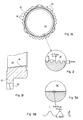
- FIGS. 1A and 1B represent a front view and an enlarged partial section view of a synchronization ring classic.
- the ring includes teeth or dogs 10 regularly distributed around its perimeter. As can be seen at FIG. 1B, the dogs 10 extend only over part of the height of the ring and are flush with one end of it. Furthermore, the ring has a thinned peripheral zone 12 which connects to the dogs 10.
- the synchronization ring has a central bore conical 14, the largest diameter being on the side of the dogs 10, as can be seen in FIG. 1B.
- This tapered bore is intended to cooperate with a conical bearing of a shaft (not shown) by axial translation to ensure synchronization fast rotation speeds of the ring and the shaft by friction then equalization of the speeds of the conical parts.
- FIG. 2 represents a conventional solution used to improve the synchronization of the conical parts of the ring and tree.
- This figure 2 represents an enlargement of the wall of the conical bore 14, as shown in the figure 1A.
- the bore 14 is provided with axial teeth 16 regularly distributed over the surface of the bore.
- the teeth 16 are provided with a flat of about 0.7 mm and have a height of about 1 mm.
- the pitch of the teeth is of the order of 1.5 mm.
- the flats are of course curved so as to form the tapered bore surface 14.
- An advantage of the synchronization ring that comes to be described, in particular the axial configuration of the teeth 16, is that it offers no undercut surface, and therefore it can be obtained by sintering.
- An object of the present invention is to provide a synchronization ring which can be made in one sintering operation while offering characteristics of particularly good friction.
- the present invention provides a synchronization ring with a tapered internal bore with sharp axial teeth.
- the tops of the teeth have a lower width flat 0.2 mm.
- the pitch of the teeth is less than 0.7 mm.
- the height of the teeth is less than 0.4 mm.
- the ring is sintered.
- the teeth of the central bore are provided with flats of approximately 0.7 mm. Despite the presence of these teeth, we do not get the desired friction characteristics on a tapered seat tree, which requires the use of effort high axial to obtain equalization of the ring speeds synchronization and tree.
- the bad friction characteristics are due to the presence an important lubricant film which is systematically created between the flats of the teeth 16 and the conical bearing of the shaft, this despite the existence of oil evacuation routes between the teeth.
- teeth with sharp peaks the teeth being always arranged in the axial direction of the ring in order to make the synchronization ring by sintering.
- the sharpest peaks that we can obtain have flats or rounded which depend of the manufacturing technique used.
- the vertices will have a flatness less than 0.2 mm, usually of the order of 0.1 mm.
- FIG. 3A represents, on the same scale as the Figure 2, an enlarged view of the bore wall of a ring synchronization according to the present invention.
- the teeth are smaller and more close together.
- FIG. 3B represents an enlarged view of the teeth of Figure 3A.
- these teeth have a flattened 0.1 mm, a pitch of 0.6 mm, a height of 0.3 mm and an angle at 60 ° summit.
- the 0.1 mm dimension of the flats is substantially the smallest dimension that can be obtained by sintering. These dimensions are of course variable, but we preferably choose a flat less than 0.2 mm, a pitch less than 0.7 mm and a height less than 0.4 mm.
- the teeth sharp according to the present invention offer the advantage of hunting the maximum of oil found at the tops of the teeth.
- the friction characteristics obtained are optimal for allow fast synchronization.
- a synchronization ring according to the invention will be preferably sintered, which makes it possible to obtain a ring finished in a single manufacturing step.
- the powder used for sintering can be the one used for classic rings.
Landscapes
- Engineering & Computer Science (AREA)
- General Engineering & Computer Science (AREA)
- Mechanical Engineering (AREA)
- Powder Metallurgy (AREA)
- Mechanical Operated Clutches (AREA)
Applications Claiming Priority (2)
| Application Number | Priority Date | Filing Date | Title |
|---|---|---|---|
| FR9807942A FR2780120B1 (fr) | 1998-06-19 | 1998-06-19 | Bague de synchronisation frittee |
| FR9807942 | 1998-06-19 |
Publications (1)
| Publication Number | Publication Date |
|---|---|
| EP0965769A1 true EP0965769A1 (de) | 1999-12-22 |
Family
ID=9527759
Family Applications (1)
| Application Number | Title | Priority Date | Filing Date |
|---|---|---|---|
| EP99410078A Withdrawn EP0965769A1 (de) | 1998-06-19 | 1999-06-18 | Gesinterter Synchronring |
Country Status (2)
| Country | Link |
|---|---|
| EP (1) | EP0965769A1 (de) |
| FR (1) | FR2780120B1 (de) |
Cited By (3)
| Publication number | Priority date | Publication date | Assignee | Title |
|---|---|---|---|---|
| FR2860846A1 (fr) * | 2003-10-14 | 2005-04-15 | Fedreal Mogul Sintered Product | Bague de synchronisation frittee |
| WO2006079762A1 (fr) * | 2005-01-31 | 2006-08-03 | Federal Mogul Operations France S.A.S | Bague de synchronisation et son procede de fabrication |
| WO2014082633A1 (de) * | 2012-11-28 | 2014-06-05 | Schaeffler Technologies AG & Co. KG | Synchronisiereinrichtung eines kraftfahrzeug-zahnräderwechselgetriebes |
Citations (4)
| Publication number | Priority date | Publication date | Assignee | Title |
|---|---|---|---|---|
| US4157135A (en) * | 1977-11-21 | 1979-06-05 | General Motors Corporation | Clutch lock-up mechanism |
| US4209086A (en) * | 1978-03-14 | 1980-06-24 | Diehl Gmbh & Co. | Synchromesh gear |
| US4267912A (en) * | 1977-10-06 | 1981-05-19 | Borg-Warner-Stieber Gmbh | Synchronizing ring |
| DE3532672A1 (de) * | 1984-09-20 | 1986-03-27 | Zahnradfabrik Friedrichshafen Ag, 7990 Friedrichshafen | Ring mit schicht aus reibwerkstoff auf kegelflaeche |
-
1998
- 1998-06-19 FR FR9807942A patent/FR2780120B1/fr not_active Expired - Lifetime
-
1999
- 1999-06-18 EP EP99410078A patent/EP0965769A1/de not_active Withdrawn
Patent Citations (4)
| Publication number | Priority date | Publication date | Assignee | Title |
|---|---|---|---|---|
| US4267912A (en) * | 1977-10-06 | 1981-05-19 | Borg-Warner-Stieber Gmbh | Synchronizing ring |
| US4157135A (en) * | 1977-11-21 | 1979-06-05 | General Motors Corporation | Clutch lock-up mechanism |
| US4209086A (en) * | 1978-03-14 | 1980-06-24 | Diehl Gmbh & Co. | Synchromesh gear |
| DE3532672A1 (de) * | 1984-09-20 | 1986-03-27 | Zahnradfabrik Friedrichshafen Ag, 7990 Friedrichshafen | Ring mit schicht aus reibwerkstoff auf kegelflaeche |
Cited By (7)
| Publication number | Priority date | Publication date | Assignee | Title |
|---|---|---|---|---|
| FR2860846A1 (fr) * | 2003-10-14 | 2005-04-15 | Fedreal Mogul Sintered Product | Bague de synchronisation frittee |
| EP1524444A1 (de) * | 2003-10-14 | 2005-04-20 | Federal Mogul Operations France SAS | Synchronisierungsring |
| US7108119B2 (en) | 2003-10-14 | 2006-09-19 | Federal Mogul Operations France Sas | Sintered synchronizing ring |
| WO2006079762A1 (fr) * | 2005-01-31 | 2006-08-03 | Federal Mogul Operations France S.A.S | Bague de synchronisation et son procede de fabrication |
| FR2881365A1 (fr) * | 2005-01-31 | 2006-08-04 | Fed Mogul Operations France Sa | Bague de synchronisation et son procede de fabrication |
| WO2014082633A1 (de) * | 2012-11-28 | 2014-06-05 | Schaeffler Technologies AG & Co. KG | Synchronisiereinrichtung eines kraftfahrzeug-zahnräderwechselgetriebes |
| CN104813054A (zh) * | 2012-11-28 | 2015-07-29 | 舍弗勒技术股份两合公司 | 机动车辆齿轮变速器的同步装置 |
Also Published As
| Publication number | Publication date |
|---|---|
| FR2780120B1 (fr) | 2000-09-08 |
| FR2780120A1 (fr) | 1999-12-24 |
Similar Documents
| Publication | Publication Date | Title |
|---|---|---|
| FR2611232A1 (fr) | Piston pour moteurs a combustion interne et machines analogues | |
| FR2896827A1 (fr) | Assemblage a encombrement radial reduit entre un arbre de turbine et un tourillon d'arbre de compresseur de turbomachine | |
| CA2894587C (fr) | Organe de guidage sous forme d'une bague pour le montage avec frottement et avec capacite d'articulation et/ou de coulissement d'un element. | |
| FR3038950A1 (de) | ||
| FR3014534A1 (fr) | Ensemble pour la realisation d'un joint filete pour le forage et l'exploitation des puits d'hydrocarbures et joint filete resultant | |
| FR2809781A1 (fr) | Organe de fixation a empreinte d'extremite dans une partie terminale filetee | |
| FR2975455A1 (fr) | Unite de synchronisation d'une boite de vitesses | |
| EP3004692B1 (de) | Getriebe mit schmierung eines synchrongetriebes | |
| EP3807508B1 (de) | Rotierender planetenträger für ein mechanisches untersetzungsgetriebe einer turbomaschine | |
| FR2780120A1 (fr) | Bague de synchronisation frittee | |
| EP1431597B1 (de) | Herstellungsverfahren eines metallischen Kugelgelenks | |
| EP1524444A1 (de) | Synchronisierungsring | |
| FR2930010A1 (fr) | Boite de vitesses pour vehicule | |
| EP3289200B1 (de) | System zur veränderung des verdichtungsverhältnisses einer brennkraftmaschine mit einem flüssigschmiermittelleitelement | |
| FR3046643B1 (fr) | "synchroniseur de boite de vitesses" | |
| EP1731795A2 (de) | Rückwärtsgang-Schaltvorrichtung für ein Schaltgetriebe | |
| EP1844170B1 (de) | Synchronring und herstellungsverfahren dafür | |
| FR3035681A1 (fr) | Piece excentrique pour systeme de variation du taux de compression d'un moteur thermique | |
| FR2802591A1 (fr) | Vilebrequin mecano-soude et son procede de fabrication | |
| FR3093776A1 (fr) | Moyeu cannele, dispositif d’assemblage cannele, vehicule comprenant ce dispositif. | |
| EP0999374A1 (de) | Synchronisiervorrichtung für ein Schaltgetriebe und ein Knickelement dafür | |
| FR3101387A1 (fr) | Porte-satellite pour réducteur épicycloïdal, avec espace de stockage de lubrifiant | |
| FR2545547A1 (fr) | Machine hydraulique a engrenage | |
| BE417271A (de) | ||
| EP1216367A1 (de) | Planetengetriebe |
Legal Events
| Date | Code | Title | Description |
|---|---|---|---|
| PUAI | Public reference made under article 153(3) epc to a published international application that has entered the european phase |
Free format text: ORIGINAL CODE: 0009012 |
|
| AK | Designated contracting states |
Kind code of ref document: A1 Designated state(s): DE ES FR IT |
|
| AX | Request for extension of the european patent |
Free format text: AL;LT;LV;MK;RO;SI |
|
| 17P | Request for examination filed |
Effective date: 20000603 |
|
| AKX | Designation fees paid |
Free format text: DE ES FR IT |
|
| STAA | Information on the status of an ep patent application or granted ep patent |
Free format text: STATUS: THE APPLICATION IS DEEMED TO BE WITHDRAWN |
|
| 18D | Application deemed to be withdrawn |
Effective date: 20020103 |