EP0965799B1 - Anordnung zur Klimatisierung von Räumen oder dergleichen - Google Patents
Anordnung zur Klimatisierung von Räumen oder dergleichen Download PDFInfo
- Publication number
- EP0965799B1 EP0965799B1 EP99104055A EP99104055A EP0965799B1 EP 0965799 B1 EP0965799 B1 EP 0965799B1 EP 99104055 A EP99104055 A EP 99104055A EP 99104055 A EP99104055 A EP 99104055A EP 0965799 B1 EP0965799 B1 EP 0965799B1
- Authority
- EP
- European Patent Office
- Prior art keywords
- air
- air conditioning
- controller
- conditioning units
- temperature
- Prior art date
- Legal status (The legal status is an assumption and is not a legal conclusion. Google has not performed a legal analysis and makes no representation as to the accuracy of the status listed.)
- Revoked
Links
- 238000004378 air conditioning Methods 0.000 title claims abstract description 47
- 238000001816 cooling Methods 0.000 claims abstract description 6
- 238000012544 monitoring process Methods 0.000 claims description 6
- 238000010438 heat treatment Methods 0.000 claims 2
- 238000004519 manufacturing process Methods 0.000 abstract description 5
- 238000010792 warming Methods 0.000 abstract 2
- 230000001419 dependent effect Effects 0.000 description 3
- 230000001105 regulatory effect Effects 0.000 description 2
- 238000010276 construction Methods 0.000 description 1
- 239000002826 coolant Substances 0.000 description 1
- 230000004069 differentiation Effects 0.000 description 1
- 238000005057 refrigeration Methods 0.000 description 1
Images


Classifications
-
- F—MECHANICAL ENGINEERING; LIGHTING; HEATING; WEAPONS; BLASTING
- F24—HEATING; RANGES; VENTILATING
- F24F—AIR-CONDITIONING; AIR-HUMIDIFICATION; VENTILATION; USE OF AIR CURRENTS FOR SCREENING
- F24F11/00—Control or safety arrangements
- F24F11/30—Control or safety arrangements for purposes related to the operation of the system, e.g. for safety or monitoring
-
- F—MECHANICAL ENGINEERING; LIGHTING; HEATING; WEAPONS; BLASTING
- F24—HEATING; RANGES; VENTILATING
- F24F—AIR-CONDITIONING; AIR-HUMIDIFICATION; VENTILATION; USE OF AIR CURRENTS FOR SCREENING
- F24F11/00—Control or safety arrangements
- F24F11/62—Control or safety arrangements characterised by the type of control or by internal processing, e.g. using fuzzy logic, adaptive control or estimation of values
-
- F—MECHANICAL ENGINEERING; LIGHTING; HEATING; WEAPONS; BLASTING
- F24—HEATING; RANGES; VENTILATING
- F24F—AIR-CONDITIONING; AIR-HUMIDIFICATION; VENTILATION; USE OF AIR CURRENTS FOR SCREENING
- F24F11/00—Control or safety arrangements
- F24F11/70—Control systems characterised by their outputs; Constructional details thereof
- F24F11/80—Control systems characterised by their outputs; Constructional details thereof for controlling the temperature of the supplied air
- F24F11/83—Control systems characterised by their outputs; Constructional details thereof for controlling the temperature of the supplied air by controlling the supply of heat-exchange fluids to heat-exchangers
Definitions
- the invention relates to an arrangement for the air conditioning of Spaces or the like according to the preamble of the claim 1.
- Such an arrangement is known for example from US-A-5558274.
- a non-differentiable over the space surface air flow over a ceiling, preferably filter cover, blown into a room after the air flow was cooled or heated accordingly via an air conditioner In known arrangements for air conditioning of rooms or the like, a non-differentiable over the space surface air flow over a ceiling, preferably filter cover, blown into a room after the air flow was cooled or heated accordingly via an air conditioner.
- an air conditioner which are used in particular for the air conditioning of clean rooms, thus a single unit for air conditioning of the air is used, which also includes a blower, so that a circulation of the air flow is made by the air conditioner on a filter blanket through the room and the air conditioner.
- the disadvantage of such an arrangement is the comparatively high pressure loss as a result of high resistances, for example by a plurality of throttle valves, which are arranged in the filter cover and should generate a uniform air flow over the space area.
- Another disadvantage of this known arrangement is that the filter cover with one and the same air flow, ie with air at the same temperature is charged and thus a differentiation of the air temperatures in the direction of the room is not possible.
- Another disadvantage is that a high specific drive power of, for example, 200 to 400 watts per m 2 is required and these disadvantages lead to the result that high demands on the constancy of the room temperature can not be met.
- the invention is therefore based on the object, an arrangement of the type mentioned above to improve such that the room temperature regulated with high accuracy and speed can be, i. that high demands on the constancy of Room temperature can be met.
- the invention provides an arrangement for the air conditioning of Spaces or the like, in which a plurality of individual Air conditioning units distributed over the room area provided are each separately controlled, i. it is a modular construction of air conditioning units provided each individually dependent on their output actual temperature are controllable.
- the air conditioning units according to the invention are preferably in Connection with a climatic ceiling above the ceiling level distributed and preferably produce a substantially vertical Air flow from top to bottom, such that per unit of air the output air temperature detected detected and is adjustable as needed.
- the output side each air conditioning unit one to a predetermined Setpoint controlled air outlet temperature reached, the is the same across the entire room area, whereby the Air temperature over the entire room area away constant can be.
- the arrangement according to the invention is particularly suitable in connection with machines, manufacturing plants, processing lines etc., where different across the room area Temperatures are being developed, something across the room different temperature, i. different temperature gradients results.
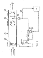
- FIG. Figure 1 shows schematically an illustration of the inventive arrangement in Connection with an application example.
- the inventive Arrangement has several air conditioning units 1, 2, 3, 4, 5 on, either integrated into a climatic ceiling or above a filter cover 6 forming this climatic ceiling is provided.
- each air conditioner in the produces a substantially vertically downward flow of air, as shown by arrows 8.
- Below the general with 9 designated Klimadecke is one or it
- These Machine 11 or the like is thus within a designated 12 space and is from above with a Airflow fed from individual airflow components composed according to the arrows 8 and on the machine 11 or the like is directed.
- the individual air conditioning units 1 to 5 are according to Art a modular system arranged above the filter cover 6,
- Figure 1 is only a view over, for example, the width of the room reproduces the units accordingly several times in Room length are provided, i. it may be essential more than five air conditioning units provided.
- the machine or production line 11 or the like is at the preferred application shown in Figure 1 on a grid-shaped bottom 13 placed, causing the top to bottom bottom air flow through the grid-shaped bottom 13 pass through and laterally along the space 12 along which is divided into individual airflow components, the individual air conditioning units 1 to 5 is returned.
- the different units such as engines, etc. may include occurs in the region of the grid-like bottom 13 an air flow on, which consists of individual components of different temperature can exist or will exist. Consequently lies in the inflow area the individual air conditioning units 1 to 5 an air flow before, the different temperature gradients includes. Purpose and purpose of the arrangement according to the invention it is different at entry side of each air conditioning unit Temperatures to treat the air so that the outlet side the individual air components are practically the same Have temperature values. By the plurality or majority of individual air conditioning units 1 to 5, this can be simple Way and safely achieved, as follows will be described.
- Each air conditioning unit is according to a first embodiment, which is described in connection with Figure 2, from an air cooler 15, a preferably downstream fan 16 and subsequent filter 17, which is part of the in Figure 1 may be designated 6 filter cover.
- a temperature sensor 18 is via a regulator 19 with a control valve 20 in connection.
- the control valve 20 is located in one Coolant circuit between a not shown Refrigeration and the air cooler 15.
- the controller 19 includes a Setpoint generator 22, which optionally has a designated 23 Monitoring unit is variable, wherein the monitoring unit 23 via a connection 24 the actual temperature value receives over the sensor 18.
- FIG. 1 is a diagrammatic representation of the air conditioning unit shown in FIG. 1
- the air cooler 15 controlled to the temperature of the air conditioning unit 1 exiting air to a predetermined setpoint.
- Figure 2 is an example of the structure of the individual air conditioning units 1 to 5 according to FIG. 1
- FIG. 3 shows an embodiment modified relative to FIG. 2 an air conditioning unit 1, with respect to Figure 2 like parts are provided with the same reference numerals.
- the air conditioning unit 1 additionally contains to the components described in connection with Figure 2 a Air heater 26, preferably an electric air heater, the in this embodiment, preferably between the air cooler 15 and the fan 16 is arranged.
- a Air heater 26 preferably an electric air heater
- FIG. 3 shows the temperature sensor or temperature sensor 23 connected to a controller 28, the output side with the Air heater 26 on the one hand and an actual value input 29 of the 19 designated regulator is connected.
- the controller 19 thus receives as an actual value (Controlled variable) not the value of the air temperature at the temperature sensor 23, but the control value of the controller 28.
- the air heater 26 the air cooler downstream and causes a quick readjustment the air which has passed through the air cooler 15.
- Air conditioning units is corresponding in an arrangement 1 shows a temperature control on the output side of the air conditioning units of preferably 20 ° C ⁇ 0.1 ° C in combination with cleanroom systems possible, while the control accuracy according to the invention in locally fluctuating cooling loads also for highly accurate applications with a constant temperature of ⁇ 0.01 ° C can be designed.
- each air conditioning unit 1 to 5 with an air conditioning unit in conjunction with FIG. 3 the controller 28 takes over the regulation of the air temperature.
- the regulator 19 for the air cooler 15 receives the manipulated variable of the controller 28 as an input variable and controls this to a predetermined setpoint, i. of the Air cooler holds just as much cooling power that the electric air heater 26 engaged in a fixed part of his performance remains.
- a higher-order Control or monitoring 23 may be provided, which the individual air conditioning units 1 to 5 scans sequentially or controls and, where appropriate, a change in the setpoints the controller 19, 28 causes and the rest with the individual Temperature sensors 18 is connected.
Landscapes
- Engineering & Computer Science (AREA)
- Chemical & Material Sciences (AREA)
- Combustion & Propulsion (AREA)
- Mechanical Engineering (AREA)
- General Engineering & Computer Science (AREA)
- Physics & Mathematics (AREA)
- Fuzzy Systems (AREA)
- Mathematical Physics (AREA)
- Signal Processing (AREA)
- Air Conditioning Control Device (AREA)
- Central Air Conditioning (AREA)
Description
- Figur 1
- eine schematische Darstellung der erfindungsgemäßen Anordnung in Verbindung mit einer bevorzugten Anwendung,
- Figur 2
- eine Detaildarstellung zur Erläuterung einer bevorzugten Ausführungsform einer Klimatisierungseinheit,
- Figur 3
- eine Figur 2 entsprechende Darstellung mit einer gegenüber Figur 2 abgewandelten Ausführungsform einer Klimatisierungseinheit.
Claims (8)
- Anordnung zur Klimatisierung von Räumen oder dergleichen, mit einer geregelten Einrichtung zur Kühlung und/oder Erhitzung der Lufttemperatur,
dadurch gekennzeichnet, daß mehrere Klimatisierungseinheiten (1 bis 5) zum Kühlen und/oder Erhitzen einer Luftströmung vorgesehen sind, von welchen jeden Klimatisierungseinheit (1 bis 5) mit einer eigenen Regelung (19; 19, 28) versehen ist, und
daß die Klimatisierungseinheiten (1 bis 5) im wesentlichen in der gleichen Ebene oberhalb einer Maschine, Fertigungsstraße (11) oder dergleichen angeordnet sind. - Anordnung nach Anspruch 1,
dadurch gekennzeichnet, daß jede Klimatisierungseinheit einen Luftkühler (15), ein Gebläse (16) und einen Filter (17) aufweist, und
daß der Luftkühler (15) über einen Regler (19) abhängig von dem Lufttemperatur-Istwert ausgangsseitig jeder Klimatisierungseinheit (1 bis 5) gesteuert wird. - Anordnung nach Anspruch 1,
dadurch gekennzeichnet, daß jede Klimatisierungseinheit (1 bis 5) einen Luftkühler (15), einen Lufterhitzer (26), ein Gebläse (16) und einen Filter (17) aufweist,
daß ein Temperaturfühler (18) ausgangsseitig in der Klimatisierungseinheit (1 bis 5) vorgesehen und über einen Regler (28) mit dem Lufterhitzer (26) einerseits sowie mit einem weiteren Regler (19) andererseits verbunden ist, welcher den Luftkühler (15) steuert. - Anordnung nach einem der vorangehenden Ansprüche,
dadurch gekennzeichnet, daß eine Überwachungs- und Kontrolleinheit (23) vorgesehen ist, die mit jedem Regler (19, 28) verbunden ist. - Anordnung nach Anspruch 4,
dadurch gekennzeichnet, daß die Überwachungs- und Kontrolleinheit (23) sequentiell mit den einzelnen Klimatisierungseinheiten (1 bis 5) verbunden wird. - Anordnung nach wenigstens einem der vorangehenden Ansprüche,
dadurch gekennzeichnet, daß die einzelnen Klimatisierungseinheiten (1 bis 5) in eine Klimadecke (6) integriert sind. - Anordnung nach einem der vorangehenden Ansprüche,
dadurch gekennzeichnet, daß jeder Regler (19, 28) einen Sollwertgeber aufweist oder mit einem Sollwertgeber verbunden ist, der mit der Überwachungs- und Kontrolleinheit (23) verbindbar ist. - Anordnung nach wenigstens einem der vorangehenden Ansprüche,
dadurch gekennzeichnet, daß die Luftströmung der Klimatisierungseinheiten (1 bis 5) nach Passieren einer Maschine, Bearbeitungsstraße (11) oder dergleichen durch einen gitterförmigen Boden geleitet und zu den Eintrittsseiten der Klimatisierungseinheiten (1 bis 5) zurückgeführt wird.
Applications Claiming Priority (2)
| Application Number | Priority Date | Filing Date | Title |
|---|---|---|---|
| DE19827447A DE19827447C1 (de) | 1998-06-19 | 1998-06-19 | Anordnung zur Klimatisierung von Räumen |
| DE19827447 | 1998-06-19 |
Publications (3)
| Publication Number | Publication Date |
|---|---|
| EP0965799A2 EP0965799A2 (de) | 1999-12-22 |
| EP0965799A3 EP0965799A3 (de) | 2003-01-15 |
| EP0965799B1 true EP0965799B1 (de) | 2005-11-23 |
Family
ID=7871461
Family Applications (1)
| Application Number | Title | Priority Date | Filing Date |
|---|---|---|---|
| EP99104055A Revoked EP0965799B1 (de) | 1998-06-19 | 1999-03-17 | Anordnung zur Klimatisierung von Räumen oder dergleichen |
Country Status (3)
| Country | Link |
|---|---|
| EP (1) | EP0965799B1 (de) |
| AT (1) | ATE310929T1 (de) |
| DE (2) | DE19827447C1 (de) |
Families Citing this family (1)
| Publication number | Priority date | Publication date | Assignee | Title |
|---|---|---|---|---|
| DE102004033337B3 (de) * | 2004-07-09 | 2006-03-02 | Smart Micro Engineering GmbH Gesellschaft für High-Tech-Industrieplanung | Klimatisierungsvorrichtung mit einer Drosselvorrichtung |
Family Cites Families (3)
| Publication number | Priority date | Publication date | Assignee | Title |
|---|---|---|---|---|
| JPS5872826A (ja) * | 1981-10-24 | 1983-04-30 | Nichiden Koumu Center:Kk | クリ−ンル−ム用の空調装置 |
| JPH0723788B2 (ja) * | 1990-02-22 | 1995-03-15 | 高砂熱学工業株式会社 | クリーンルーム構築システム |
| US5558274A (en) * | 1995-03-24 | 1996-09-24 | Johnson Service Company | Dual duct control system |
-
1998
- 1998-06-19 DE DE19827447A patent/DE19827447C1/de not_active Expired - Lifetime
-
1999
- 1999-03-17 DE DE59912813T patent/DE59912813D1/de not_active Expired - Fee Related
- 1999-03-17 AT AT99104055T patent/ATE310929T1/de not_active IP Right Cessation
- 1999-03-17 EP EP99104055A patent/EP0965799B1/de not_active Revoked
Also Published As
| Publication number | Publication date |
|---|---|
| EP0965799A3 (de) | 2003-01-15 |
| DE59912813D1 (de) | 2005-12-29 |
| ATE310929T1 (de) | 2005-12-15 |
| DE19827447C1 (de) | 1999-12-16 |
| EP0965799A2 (de) | 1999-12-22 |
Similar Documents
| Publication | Publication Date | Title |
|---|---|---|
| DE19654955C2 (de) | Klimatisierungsvorrichtung | |
| EP0851179B1 (de) | Klimatisierungsvorrichtung und Verfahren zur Klimatisierung eines Raumes | |
| EP2943727B1 (de) | Mehrkanal-klimaanlage | |
| DE19711031A1 (de) | Heizungs-, Lüftungs- und/oder Klimaanlage mit Leistungsregelung, insbesondere für Kraftfahrzeuge | |
| DE60127629T2 (de) | Luftbehandlungs- und Belüftungsvorrichtung | |
| EP0942237B1 (de) | Lüftungs-Heizvorrichtung | |
| EP1393938B1 (de) | Verfahren und Vorrichtung zur Temperierung von Luft in wenigstens zwei Bereichen eines Raumes | |
| EP0965799B1 (de) | Anordnung zur Klimatisierung von Räumen oder dergleichen | |
| DE60205523T2 (de) | Luftmischungsystem mit einer Flüssigkeitsablenkvorrichtung von analoger Art | |
| EP2890936B1 (de) | Verfahren zur bedarfsgerechten regelung einer vorrichtung für eine schichtlüftung und vorrichtung für eine schichtlüftung | |
| EP0053269A2 (de) | Vorrichtung zur Wärmebehandlung von bahnförmigem Gut | |
| DE102008007641B4 (de) | Lüftungsgerät | |
| DE3407458C2 (de) | ||
| DE102006061801B4 (de) | Verfahren zum Kühl- oder Heizbetrieb eines Systems zur Regelung einer Innentemperatur mindestens eines Raumes eines Gebäudes | |
| EP1568523B1 (de) | Bauanordnung für eine Vorrichtung zum Austausch von Wärme | |
| EP0085428B1 (de) | Verfahren und Vorrichtung für die Belüftung von Räumen | |
| EP0847887B1 (de) | Mehrkanalige Heiz- oder Klimaanlage | |
| EP0239842A1 (de) | Verfahren zum Regeln der Innenraumtemperatur, insbesondere eines Kraftfahrzeugs | |
| DE10221254B4 (de) | Verfahren und Vorrichtung zum Entfeuchten von Lebensmitteln | |
| DE2949950C2 (de) | Einrichtung zum Klimatisieren mehrerer Räume unabhängig schwankenden Wärmebedarfs | |
| DE2634713B2 (de) | Verfahren und Vorrichtung zum Beheizen und Belüften des Innenraums von Omnibussen | |
| DE1805475B2 (de) | Vorrichtung zum temperieren und belueften von raeumen | |
| DE10327120A1 (de) | Bauanordnung für eine Klimaanlage | |
| DE10314803B4 (de) | Verfahren zum Entfeuchten und Temperieren eines Luftstromes | |
| DE3639010C2 (de) |
Legal Events
| Date | Code | Title | Description |
|---|---|---|---|
| PUAI | Public reference made under article 153(3) epc to a published international application that has entered the european phase |
Free format text: ORIGINAL CODE: 0009012 |
|
| AK | Designated contracting states |
Kind code of ref document: A2 Designated state(s): AT BE CH CY DE DK ES FI FR GB GR IE IT LI LU MC NL PT SE |
|
| AX | Request for extension of the european patent |
Free format text: AL;LT;LV;MK;RO;SI |
|
| PUAL | Search report despatched |
Free format text: ORIGINAL CODE: 0009013 |
|
| AK | Designated contracting states |
Kind code of ref document: A3 Designated state(s): AT BE CH CY DE DK ES FI FR GB GR IE IT LI LU MC NL PT SE |
|
| AX | Request for extension of the european patent |
Free format text: AL;LT;LV;MK;RO;SI |
|
| RIC1 | Information provided on ipc code assigned before grant |
Free format text: 7F 24F 11/00 A, 7G 05D 23/19 B |
|
| 17P | Request for examination filed |
Effective date: 20030702 |
|
| AKX | Designation fees paid |
Designated state(s): AT BE CH DE FR IT LI NL |
|
| GRAP | Despatch of communication of intention to grant a patent |
Free format text: ORIGINAL CODE: EPIDOSNIGR1 |
|
| GRAS | Grant fee paid |
Free format text: ORIGINAL CODE: EPIDOSNIGR3 |
|
| GRAA | (expected) grant |
Free format text: ORIGINAL CODE: 0009210 |
|
| AK | Designated contracting states |
Kind code of ref document: B1 Designated state(s): AT BE CH DE FR IT LI NL |
|
| PG25 | Lapsed in a contracting state [announced via postgrant information from national office to epo] |
Ref country code: NL Free format text: LAPSE BECAUSE OF FAILURE TO SUBMIT A TRANSLATION OF THE DESCRIPTION OR TO PAY THE FEE WITHIN THE PRESCRIBED TIME-LIMIT Effective date: 20051123 Ref country code: IT Free format text: LAPSE BECAUSE OF FAILURE TO SUBMIT A TRANSLATION OF THE DESCRIPTION OR TO PAY THE FEE WITHIN THE PRESCRIBED TIME-LIMIT;WARNING: LAPSES OF ITALIAN PATENTS WITH EFFECTIVE DATE BEFORE 2007 MAY HAVE OCCURRED AT ANY TIME BEFORE 2007. THE CORRECT EFFECTIVE DATE MAY BE DIFFERENT FROM THE ONE RECORDED. Effective date: 20051123 |
|
| REG | Reference to a national code |
Ref country code: CH Ref legal event code: EP |
|
| REF | Corresponds to: |
Ref document number: 59912813 Country of ref document: DE Date of ref document: 20051229 Kind code of ref document: P |
|
| PG25 | Lapsed in a contracting state [announced via postgrant information from national office to epo] |
Ref country code: LI Free format text: LAPSE BECAUSE OF NON-PAYMENT OF DUE FEES Effective date: 20060331 Ref country code: CH Free format text: LAPSE BECAUSE OF NON-PAYMENT OF DUE FEES Effective date: 20060331 Ref country code: BE Free format text: LAPSE BECAUSE OF NON-PAYMENT OF DUE FEES Effective date: 20060331 |
|
| NLV1 | Nl: lapsed or annulled due to failure to fulfill the requirements of art. 29p and 29m of the patents act | ||
| PLBI | Opposition filed |
Free format text: ORIGINAL CODE: 0009260 |
|
| PLAX | Notice of opposition and request to file observation + time limit sent |
Free format text: ORIGINAL CODE: EPIDOSNOBS2 |
|
| 26 | Opposition filed |
Opponent name: SME SMART MICRO ENGINEERING GMBH Effective date: 20060818 |
|
| PG25 | Lapsed in a contracting state [announced via postgrant information from national office to epo] |
Ref country code: DE Free format text: LAPSE BECAUSE OF NON-PAYMENT OF DUE FEES Effective date: 20061003 |
|
| PG25 | Lapsed in a contracting state [announced via postgrant information from national office to epo] |
Ref country code: FR Free format text: LAPSE BECAUSE OF FAILURE TO SUBMIT A TRANSLATION OF THE DESCRIPTION OR TO PAY THE FEE WITHIN THE PRESCRIBED TIME-LIMIT Effective date: 20061020 |
|
| REG | Reference to a national code |
Ref country code: CH Ref legal event code: PL |
|
| RDAF | Communication despatched that patent is revoked |
Free format text: ORIGINAL CODE: EPIDOSNREV1 |
|
| EN | Fr: translation not filed | ||
| RDAG | Patent revoked |
Free format text: ORIGINAL CODE: 0009271 |
|
| STAA | Information on the status of an ep patent application or granted ep patent |
Free format text: STATUS: PATENT REVOKED |
|
| 27W | Patent revoked |
Effective date: 20061222 |
|
| BERE | Be: lapsed |
Owner name: PCS PROCESS CONTROL SYSTEMS GMBH G.- FUR STEUERUN Effective date: 20060331 |
|
| PG25 | Lapsed in a contracting state [announced via postgrant information from national office to epo] |
Ref country code: FR Free format text: LAPSE BECAUSE OF FAILURE TO SUBMIT A TRANSLATION OF THE DESCRIPTION OR TO PAY THE FEE WITHIN THE PRESCRIBED TIME-LIMIT Effective date: 20051123 |