EP0965875A1 - Flüssigkristallvorrichtung sowie ein Projektionsanzeigegerät, welches eine solche Vorrichtung verwendet - Google Patents
Flüssigkristallvorrichtung sowie ein Projektionsanzeigegerät, welches eine solche Vorrichtung verwendet Download PDFInfo
- Publication number
- EP0965875A1 EP0965875A1 EP99304610A EP99304610A EP0965875A1 EP 0965875 A1 EP0965875 A1 EP 0965875A1 EP 99304610 A EP99304610 A EP 99304610A EP 99304610 A EP99304610 A EP 99304610A EP 0965875 A1 EP0965875 A1 EP 0965875A1
- Authority
- EP
- European Patent Office
- Prior art keywords
- light
- liquid crystal
- micro
- crystal device
- lens
- Prior art date
- Legal status (The legal status is an assumption and is not a legal conclusion. Google has not performed a legal analysis and makes no representation as to the accuracy of the status listed.)
- Withdrawn
Links
- 239000004973 liquid crystal related substance Substances 0.000 title claims abstract description 214
- 238000005286 illumination Methods 0.000 claims abstract description 94
- 230000003287 optical effect Effects 0.000 claims abstract description 88
- 239000011159 matrix material Substances 0.000 claims abstract description 20
- 239000003086 colorant Substances 0.000 claims description 22
- 239000000758 substrate Substances 0.000 description 25
- 210000002858 crystal cell Anatomy 0.000 description 9
- 238000010586 diagram Methods 0.000 description 8
- 230000009467 reduction Effects 0.000 description 7
- 239000010408 film Substances 0.000 description 4
- 238000003491 array Methods 0.000 description 3
- 230000003247 decreasing effect Effects 0.000 description 2
- 239000010409 thin film Substances 0.000 description 2
- 239000000853 adhesive Substances 0.000 description 1
- 230000001070 adhesive effect Effects 0.000 description 1
- 230000005540 biological transmission Effects 0.000 description 1
- 230000008859 change Effects 0.000 description 1
- 230000000593 degrading effect Effects 0.000 description 1
- 230000001419 dependent effect Effects 0.000 description 1
- 230000001747 exhibiting effect Effects 0.000 description 1
- 230000006872 improvement Effects 0.000 description 1
- QSHDDOUJBYECFT-UHFFFAOYSA-N mercury Chemical compound [Hg] QSHDDOUJBYECFT-UHFFFAOYSA-N 0.000 description 1
- 229910052753 mercury Inorganic materials 0.000 description 1
- 229910001507 metal halide Inorganic materials 0.000 description 1
- 150000005309 metal halides Chemical class 0.000 description 1
- 230000004048 modification Effects 0.000 description 1
- 238000012986 modification Methods 0.000 description 1
- 230000010287 polarization Effects 0.000 description 1
Images







Classifications
-
- G—PHYSICS
- G02—OPTICS
- G02F—OPTICAL DEVICES OR ARRANGEMENTS FOR THE CONTROL OF LIGHT BY MODIFICATION OF THE OPTICAL PROPERTIES OF THE MEDIA OF THE ELEMENTS INVOLVED THEREIN; NON-LINEAR OPTICS; FREQUENCY-CHANGING OF LIGHT; OPTICAL LOGIC ELEMENTS; OPTICAL ANALOGUE/DIGITAL CONVERTERS
- G02F1/00—Devices or arrangements for the control of the intensity, colour, phase, polarisation or direction of light arriving from an independent light source, e.g. switching, gating or modulating; Non-linear optics
- G02F1/01—Devices or arrangements for the control of the intensity, colour, phase, polarisation or direction of light arriving from an independent light source, e.g. switching, gating or modulating; Non-linear optics for the control of the intensity, phase, polarisation or colour
- G02F1/015—Devices or arrangements for the control of the intensity, colour, phase, polarisation or direction of light arriving from an independent light source, e.g. switching, gating or modulating; Non-linear optics for the control of the intensity, phase, polarisation or colour based on semiconductor elements having potential barriers, e.g. having a PN or PIN junction
-
- G—PHYSICS
- G02—OPTICS
- G02F—OPTICAL DEVICES OR ARRANGEMENTS FOR THE CONTROL OF LIGHT BY MODIFICATION OF THE OPTICAL PROPERTIES OF THE MEDIA OF THE ELEMENTS INVOLVED THEREIN; NON-LINEAR OPTICS; FREQUENCY-CHANGING OF LIGHT; OPTICAL LOGIC ELEMENTS; OPTICAL ANALOGUE/DIGITAL CONVERTERS
- G02F1/00—Devices or arrangements for the control of the intensity, colour, phase, polarisation or direction of light arriving from an independent light source, e.g. switching, gating or modulating; Non-linear optics
- G02F1/01—Devices or arrangements for the control of the intensity, colour, phase, polarisation or direction of light arriving from an independent light source, e.g. switching, gating or modulating; Non-linear optics for the control of the intensity, phase, polarisation or colour
- G02F1/13—Devices or arrangements for the control of the intensity, colour, phase, polarisation or direction of light arriving from an independent light source, e.g. switching, gating or modulating; Non-linear optics for the control of the intensity, phase, polarisation or colour based on liquid crystals, e.g. single liquid crystal display cells
- G02F1/133—Constructional arrangements; Operation of liquid crystal cells; Circuit arrangements
- G02F1/1333—Constructional arrangements; Manufacturing methods
- G02F1/1335—Structural association of cells with optical devices, e.g. polarisers or reflectors
- G02F1/133526—Lenses, e.g. microlenses or Fresnel lenses
Definitions
- This invention relates to a liquid crystal device that modulates light in accordance with supplied image information, and to a projection display apparatus that uses the liquid crystal device.
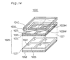
- FIG. 14 is an exploded view showing the general configuration of a conventional liquid crystal device 1000.
- the liquid crystal device 1000 is equipped with a liquid crystal cell 1020, a micro-lens array 1030 and two polarizers 1040 and 1050.
- the liquid crystal cell 1020 has a transparent substrate 1021,an opposed (transparent) substrate 1025 and a liquid crystal layer 1027 set between the transparent substrate 1021 and the opposed substrate 1025.
- a thin-film transistor 1022 and pixel electrode 1023 are provided on the transparent substrate 1021 for each pixel.
- a common electrode 1024 is provided on the opposed substrate 1025.
- a light shield layer 1026 is provided between the opposed substrate 1025 and the common electrode 1024.
- the light shield layer 1026 has a corresponding opening 1026W for each pixel electrode 1023.
- the micro-lens array 1030 is provided on the opposite side of the opposed substrate 1025 to the liquid crystal layer 1027.
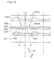
- the micro-lens array 1030 is constituted of a plurality of concentrically shaped micro-lenses 1030M. As shown by Figure 15, the micro-lenses 1030M are arranged so that the optical axis of each of the micro-lenses 1030M is substantially in alignment with the center axis of the cprresponding opening 1026W.
- the first polarizer 1040 is provided on the opposite side of the micro-lens array 1030 to the opposed substrate 1025, and the second polarizer 1050 is provided on the opposite side of the liquid crystal cell 1020 to the liquid crystal layer 1027.
- liquid crystal device 1000 light enters the liquid crystal layer 1027 via the opposed substrate 1025 and exits via the transparent substrate 1021 (the exit surface being the display surface).
- the passage of incident light through the liquid crystal device 1000 is illustrated by Figure 15.
- the incident light is split into a plurality of beams and is converged by its passage through each of the micro-lenses 1030M of the micro-lens array 1030, and then enters the opening 1026W of the corresponding pixel, from which it passes through the common electrode 1024 and pixel electrode 1023 and exits from the display surface.
- the light is caused to form an image on the display surface by using the application of a voltage (determined by the image information) between the common electrode 1024 and each pixel electrode 1023 to control (modulate) the light transmissivity of each pixel.
- the image displayed on the liquid crystal device is projected by an optical projection system (such as a projection lens) to be displayed on a screen.
- an optical projection system such as a projection lens
- a characteristic of a liquid crystal device is that it changes the contrast of the image displayed on the display surface in the direction in which the image is viewed.
- the direction in which the image is viewed is termed the viewing angle or viewing angle direction, and is expressed as the angle from the normal of the display surface and the plane angle.
- Each type of liquid crystal device also has a viewing angle direction (hereinafter referred to as "clear viewing direction") at which contrast is at a maximum (hereinafter referred to as "optimum contrast”).
- the arrow in Figure 15 indicates the clear viewing direction VD of the liquid crystal device 1000.
- the contrast of the viewed image is best when the light from the display surface of the liquid crystal device exits in a direction that is substantially parallel to the clear viewing direction VD, and when the light exits in a direction that is not parallel to the clear viewing direction VD the contrast is degraded by an amount that is dependent on the direction of the light and increases with the increase in the angle by which the light departs from being parallel with the clear viewing direction VD.
- liquid crystal devices generally employ divergent or substantially parallel light, and light emitted by the display surface includes light with the various directional components. Although it is termed substantially parallel light, the fact is that it includes quite a high proportion of non-parallel components. Therefore, since the contrast of a liquid crystal device is determined by light thus comprised of these various directional components, the contrast of the liquid crystal device is degraded compared to the optimum contrast in the clear viewing direction.
- An object of the present invention is to provide a liquid crystal device having improved contrast of displayed images compared to that of a conventional liquid crystal device.
- a first liquid crystal device that modulates light in accordance with supplied image information, comprising: a plurality of pixels arranged in a matrix, each pixel having an opening to allow passage of light; and a micro-lens array that has a plurality of micro-lenses arranged in a matrix that divides illumination light into a plurality of partial light beams and converges the light to a light incidence plane of the pixels. Characteristics of micro-lenses are adjusted to increase a proportion of light exiting from the opening of each pixel substantially parallel to a clear viewing direction of the liquid crystal device compared to a proportion of light parallel to other directions.
- nuclear viewing direction refers to the viewing angle direction at which contrast is at a maximum (optimum contrast).
- adjusting micro-lens characteristies refers to modification of the shape, refractive index or position of micro-lenses.
- the proportion of light emitted from the pixel openings that is comprised of light that is substantially parallel to the clear viewing direction of the liquid crystal device can be increased, improving the contrast compared to that of a conventional liquid crystal device.
- the micro-lenses are formed as concentric lenses and are each positioned so that an optical center thereof is offset from a center axis of each pixel to increase a proportion of light exiting from the opening of each pixel substantially parallel to the clear viewing direction of the liquid crystal device compared to the proportion of light parallel to the other directions.
- optical center corresponds to the optical axis of concentric lenses, a position along which incident light proceeds without refraction.
- a position of the optical center of each micro-lens is set so that a line connecting the optical center of each micro-lens with the center of the opening of each pixel is substantially parallel to the clear viewing direction.
- each micro-lens is formed so that a geographical center of the micro-lens is offset from an optical center of the micro-lens to increase the proportion of light exiting from the opening of each pixel substantially parallel to the clear viewing direction of the liquid crystal device compared to the proportion of light parallel to the other directions.
- the optical center of each micro-lens is offset from the geographical center of the mirco-lens to increase the proportion of light exiting from the opening of each pixel substantially parallel to the clear viewing direction of the liquid crystal device compared to the proportion of light parallel to the other directions.
- the above configuration makes it possible to align the center axis of the light entering the micro-lenses that has the highest intensity (quantity of light) so that it is directed substantially parallel to the clear viewing direction.
- the beams of light exiting the micro-lenses all exit parallel to the clear viewing direction, with each passing substantially through the center of the corresponding pixel, that is, substantially through the center of each opening.
- the optical center of the micro-lens may be also located on a center axis of the corresponding pixel of the micro-lens.
- a second liquid crystal device comprising: a plurality of pixels arranged in a matrix, each pixel having an opening to allow passage of light; and a micro-lens array that has a plurality of micro-lenses arranged in a matrix that divides illumination light into a plurality of partial light beams and converges the light to a light incidence plane of the pixels.
- each micro-lens is formed as a concentric lens, and when a clear viewing vector representing a clear viewing direction of the liquid crystal device is broken down into a y vector component and an x vector component, an optical center of each micro-lens is offset from the center axis of the opening of the pixel in a negative direction along a selected one of the y vector component and x vector component.
- the second liquid crystal device of this invention makes it possible to improve contrast compared to that of a conventional liquid crystal device.
- the second liquid crystal device even when there are differences in intensity distribution between the liquid crystal device illumination light beams having different directional components based on the illumination position, it is still possible to reduce the contrast distribution in the plane of the liquid crystal device.
- the plurality of pixels are classified into a plurality of pixel groups, the liquid crystal device being characterized in that the optical center of the micro-lenses is offset from the center axis of the pixel opening by an amount that is different in each pixel group.
- a first projection display apparatus for projecting an image comprising: liquid crystal device that modulates light in accordance with supplied image information; an illumination system that projects illumination light at the liquid crystal device; and an optical projection system for projecting modulated light exiting from the liquid crystal device.
- the liquid crystal device comprises: a plurality of pixels arranged in a matrix, each pixel having an opening to allow passage of light; and a micro-lens array that has a plurality of micro-lenses arranged in a matrix that divides illumination light into a plurality of partial light beams and converges the light to a light incidence plane of the pixels. Characteristics of micro-lenses are adjusted to increase a proportion of light exiting from the opening of each pixel substantially parallel to a clear viewing direction of the liquid crystal device compared to a proportion of light parallel to other directions.
- the contrast of displayed images can be improved compared to that of a conventional projection display apparatus.
- the micro-lenses are formed as concentric lenses and are each positiioned so that an optical center thereof is offset from a center axis of each pixel to increase a proportion of light exiting from the opening of each pixel substantially parallel to the clear viewing direction of the liquid crystal device compared to the proposition of light parallel to the other directions.
- the above illumination system refers to a broadly defined illumination system that includes so-called narrowly defined optical illumination systems having a light path that extends from the emission of light from the illumination system to the entry of the illumination light into the liquid crystal device, and the various optical systems provided along the light path.
- the above first projection display apparatus may be comprise: a color separator that separates the illumination light into a plurality of colors; a plurality of the liquid crystal devices to receive each of the plurality of colors into which the light is separated by the color separator; and a color combiner for combining light of the colors exiting the plurality of liquid crystal devices. Combined light exiting the color combiner is projected by the projection display apparatus via the optical projection system.
- a second projection display apparatus comprising: liquid crystal device that modulates light in accordance with supplied image information; an illumination system that projects illumination light at the liquid crystal device; and an optical projection system for projecting modulated light exiting from the liquid crystal device.
- the liquid crystal device comprises: a plurality of pixels arranged in a matrix, each pixel having an opening to allow passage of light; and a micro-lens array that has a plurality of micro-lenses arranged in a matrix that divides illumination light into a plurality of partial light beams and converges the light to a light incidence plane of the pixels.
- each micro-lens is formed as a concentric lens, and when a clear viewing vector representing a clear viewing direction of the liquid crystal device is broken down into a y vector component and an x vector component, an optical center of each micro-lens is offset from the center axis of the opening of the pixel in a negative direction along a selected one of the y vector component and x vector component.
- the contrast of displayed images can be improved compared to that of a conventional projection display apparatus.
- the above second projection display apparatus may be comprise: a color separator that separates the illumination light into a plurality of colors; a plurality of the liquid crystal devices to receive each of the plurality of colors into which the light is separated by the color separator; and a color combiner for combining light of the colors exiting the plurality of liquid crystal devices. Combined light exiting the color combiner is projected by the projection display apparatus via the optical projection system.
- each micro-lens is disposed with the optical center of the micro-lens offset from the center axis of the opening of the pixel along one of the y vector component and x vector component of the clear viewing direction in a negative direction that is parallel to a direction perpendicular to a plane of incidence of light of each color that exits from the plurality of liquid crystal devices into the color combiner.
- plane of incidence of light refers to a plane defined by the incident principal ray and the incident normal.
- Figure 1 is a general view showing the configuration of the principal parts of a projection display apparatus 10 according to a first embodiment.
- the projection display apparatus 10 is equipped with an illumination system 20, a field lens 70, a first liquid crystal device 80 of the invention, and a projection lens system 90. These structural components are arranged along a system optical axis 10LC with the optical axis of each component in alignment with the system optical axis 10LC.
- the illumination system 20 includes a light source 30 that emits a substantially parallel beam of light, a first lens array 40, a second lens array 50 and a superposing lens 60.
- the illumination system 20 is an optical integrator for providing substantially uniform illumination of an illumination region of the first liquid crystal device 80 (an image display region, also called "effective display region").
- the light source 30 has a light source lamp 32 for emitting light rays radially and a concave mirror 34 for emitting the light from the light source lamp 32 as a parallel beam.
- the light source lamp 32 may be a metal halide lamp or a mercury lamp or the like.
- a parabolic reflector is usually used as the concave mirror 34.
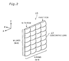
- Figure 2 is a perspective view of the first lens array 40.
- the first lens array 40 is formed as a matrix of M lines and N rows of small, substantially rectangular lenses 42.
- the small lenses 42 divide the light beam emitted by the light source 30 ( Figure 1) into a plurality (that is, M x N) of small, partial beams and focus each of these partial beams in the vicinity of the second lens array 50.
- the small lenses 42 are shaped so that when viewed from direction z each is substantially analogous in shape to the illumination region of the liquid crystal device 80. If the illumination region 80ACT ( Figure 1) of the liquid crystal device 80 has a 4:3 aspect ratio (the ratio of width to height), for example, each of the small lenses 42 is given an aspect ratio of 4:3. In the example of this embodiment, the aspect ratio of the small lenses 42 is set at 4:3.
- the second lens array 50 ( Figure 1) is also formed as a matrix of M lines and N rows of small lenses 52 that correspond to the small lenses 42 of the first lens array 40.
- the second lens array 50 functions to effectively illuminate, via the superposing lens 60, the illumination region 80ACT of the liquid crystal device 80, using the light emitted by the first lens array 40.
- the plurality of partial light beams transmitted by the first and second lens arrays 40 and 50 are superposed on the liquid crystal device 80 by the superposing lens 60.
- the function of the field lens 70 is to convert the partial light beams used for illuminating the illumination region 80ACT so that the center axes thereof are parallel.
- the second lens array 50 and superposing lens 60 are separate.
- the second lens array 50 may be configured to also have the function of the superposing lens 60.
- the small lenses may be formed as eccentric lenses.
- the substantially parallel beam of light emitted by the light source 30 is divided into a plurality of partial beams by the first and second lens arrays 40 and 50.
- the partial beams exiting the small lenses 42 of the first lens array 40 are each converged by the small lenses 42 to focus and form a light source image of the light source 30 (secondary light source image) in the vicinity of the corresponding small lenses 52 of the second lens array 50.
- the partial light beams emitted from the secondary light source images formed in the vicinity of the second lens array 50 diverge and are superposed by the superposing lens 60 over the illumination region of the liquid crystal device 80 (a region including the illumination region 80ACT).
- the light for illuminating the illumination region 80ACT is converted by the field lens 70 into light that overall is substantially parallel to the system optical axis 10LC. As a result, the illumination region 80ACT of the liquid crystal device 80 is illuminated substantially uniformly.
- the liquid crystal device 80 functiond as a light modulator that modulates the incident illumination light from the illumination system 20 in accordance with supplied image information (image signals) to thereby form an image.
- the projection lens system 90 functions as an optical projection system that displays the modulated light from the liquid crystal device 80 as an image that is projected onto a screen SC.
- FIG 3 is an enlarged cross-sectional view of a part of the first liquid crystal device 80 of this invention.
- the liquid crystal device 80 includes a liquid crystal cell 820, a micro-lens array 830 and a pair of polarizers 840 and 870, and is the same as the conventional liquid crystal device 1000 shown in Figure 14, except for the positional relationship of the micro-lens array 830 and liquid crystal cell 820.
- the liquid crystal cell 820 has a transparent substrate 821, an opposed substrate (transparent substrate) 825 and a liquid crystal layer 827 between the transparent substrate 821 and the opposed substrate 825.
- a thin-film transistor 822 and pixel electrode 824 are provided on the transparent substrate 821 for each pixel.
- a common electrode 824 is provided on the opposed substrate 825.
- a light shield layer 826 is provided between the opposed substrate 825 and the common electrode 824.
- the light shield layer 826 has a corresponding opening 826W for each pixel electrode 823. Each pixel is constiteted of one pixel electrode 823 and the common electrode 824, with the liquid crystal layer 827 disposed therebetween.
- the light shield layer 826 may be provided on the plane of incidence (the upper surface) of the opposed substrate 825, that is, on the plane of incidence of the liquid crystal cell 820, or on the transparent substrate 821.
- the micro-lens array 830 is affixed to the upper side of the opposed substrate 825 via a bonding layer 832.
- the micro-lens array 830 has a plurality of micro-lenses 830M.
- the micro-lens array 830 is constituted of concentric lenses.
- Figures 4(A) and 4(B) illustrate the positional relationship between the micro-lenses 830M and the openings 826W.
- the micro-lenses 830M making up the micro-lens array 830 are each positioned at an offset from the center axis of the opening 826W of the corresponding pixel so that a line connecting the center LC on the optical axis of each micro-lens 830M with the center AC on the optical axis of the the corresponding opening 826W is substantially parallel to vector components VDxy and VDyz in plane xy and plane yz of clear viewing vector VD representing the clear viewing direction (hereinafter also referred to simply as "clear viewing direction” or "clear viewing vector”).
- the first polarizer 840 is provided on the opposite side of the micro-lens array 830 to the opposed substrate 825, and the second polarizer 870 (figure 3) is provided on the opposite side of the transparent substrate 821 to the liquid crystal layer 827.
- the first and second polarizers 840 and 870 may be affixed to the micro-lens array 830 and liquid crystal cell 820 by adhesive, for example, or they may be associated using an assembly jig. Also, while in the drawing the polarizers 840 and 870 are shown in contact with the micro-lens array 830 and liquid crystal cell 820, they may also be provided separated therefrom.
- the passage of incident light through the liquid crystal device 80 will now be explained.
- Light entering the micro-lens array 830 is divided into small light beams by the plurality of micro-lenses 830M and each small light beam is converged by the micro-lens concerned.
- Each small beam 850 that is parallel to the clear viewing direction VD is focused in the vicinity of the corresponding pixel electrode 823.
- the center 850C of the small beam 850 substantially passes straight through the center AC of the opening 826W.
- the small beam 850 focused by the micro-lens 830M is virtually all transmitted by the opening 826W, entering the liquid crystal layer 827, and is emitted after modulation.
- light that is not parallel to the clear viewing direction VD such as, for example, small beam 852 having an angle of incidence symmetrical with that of the small beam 850, is also converged in the vicinity of the corresponding pixel electrode 823.
- the center 852C of the small beam 852 impinges at a position that is away from the center AC of the opening 826W, such as for example on shield portion 826P of the light shield layer 826, as shown in the drawing.
- Most of the small beam 852 is focused by the micro-lens 830M to impinge on the shield portion 826P, which means that almost none of the small beam 852 enters the liquid crystal layer 827.
- the amount of incident light from a direction not parallel to the clear viewing direction VD can be reduced with almost no decrease in the amount of light parallel to the clear viewing direction VD.
- the proportion of light parallel to the clear viewing direction VD can be increased.
- the liquid crystal device 80 can display images with an improved contrast compared to that of a conventional liquid crystal device.
- the projection display apparatus 10 ( Figure 1) uses the liquid crystal device 80 of this invention, the contrast of images displayed by being projected on a screen SC also is improved.
- the passage of the illumination light of the illumination system 20 through the field lens 70 makes it possible to view the light as being almost all substantially parallel to the clear viewing direction VD.
- the component of the illumination light produced by the illumination system 20 that is not parallel to the system optical axis 10LC may be larger than that of illumination light obtained without the use of an optical integrator. This is a major factor in the decrease in contrast described in the above.
- the projection display apparatus 10 uses the first liquid crystal device 80 of the invention, it is possible to control the decrease in the contrast of the image projected on the screen SC.
- the micro-lenses 830M making up the micro-lens array 830 are described as being positioned at an offset from the center axis of the corresponding pixel opening 826W whereby a line connecting the center LC on the optical axis of each micro-lens 830M with the center AC on the optical axis of the the corresponding opening 826W is substantially parallel with the clear viewing direction VD.
- the configuration may be one whereby the line connecting the center LC on the optical axis of each micro-lens 830M with the center AC on the optical axis of the the corresponding opening 826W is inclined relative to the center axis of each pixel in a direction parallel to the clear viewing direction.
- each micro-lens could be positioned out of alignment with the center axis of each pixel so as to increase the proportion of light exiting each pixel that is parallel to the clear viewing direction compared to the proportion of light that is not parallel to the clear viewing direction.
- the above embodiment has been described with reference to the example of a liquid crystal device 80 that displays monochrome images, it can be configured as a liquid crystal device for displaying color images.
- the opening 826W of the light shield layer 826 ( Figure 3) would generally be provided in turn with red, green and blue filters for each pixel, but other than that, the structural components would be the same as those of the liquid crystal device 80.
- Figure 5 is a general view showing the configuration of the principal parts of a projection display apparatus 10B according to the second embodiment. Except for the positioning of the illumination system 20 the projection display apparatus 10B is identical to the projection display apparatus 10 of the first embodiment. Therefore, further explanation of the structural components is omitted.
- optical axis 20LC of the illumination system 20 is set at an angle to the system optical axis 10LC whereby the optical axis 20LC is parallel to the clear viewing direction VD of the liquid crystal device 80.
- this enables the illumination light from the illumination system 20 to be emitted parallel to the clear viewing direction VD, thereby increasing the amount of light impinging on the liquid crystal device 80 that is parallel to the clear viewing direction VD.
- the contrast can be improved with little decrease in brightness.
- optical axis 20LC is set at an angle parallel to the clear viewing direction VD
- a configuration may be used whereby the optical axis 20LC is parallel to the system optical axis 10LC while being also displayed therefrom in the -y direction, and in which a reflecting mirror is provided between the illumination system 20 and the field lens 70.
- illumination light from the illumination system 20 could be directed in a direction parallel to the clear viewing direction VD by being reflected by the mirror.
- the light path from the emission of illumination light from the illumination system, in the narrow sense of the term, to the impingement of the light on the liquid crystal device, and illumination systems in the broad sense of the term that include various optical systems provided along this light path may be positioned so that the center axis of light incident on the liquid crystal device is substantially parallel to the clear viewing direction.
- the liquid crystal device used can be configured as one that displays color images.
- Figure 6 is a general cross-sectional enlarged view of part of a liquid crystal device 80B applied to a projection display apparatus 10C according to a third embodiment of the invention. Except for the use of the second liquid crystal device 80B in place of the first liquid crystal device 80, this projection display apparatus 10C is the same as the projection display apparatus 10 of the first embodiment shown in Figure 1. Similarly, other than the fact that micro-lens array 830B is used instead of the micro-lens array 830, the second liquid crystal device 80B is the same as the first liquid crystal device 80 shown in Figure 3. Thus, further explanation of the related structural components is omitted.
- Each of the plurality of micro-lenses 830BM comprising the micro-lens array 830B is an eccentrie lens in which the geographical center GC of the lens does not coincide with the optical center OC.
- Each of the micro-lenses 830BM is positioned at an offset to the center axis of the corresponding opening 826W whereby a line between the geographical center GC of each of the micro-lenses 830BM and the center AC of the pixel opening 826W is substantially parallel to the clear viewing direction VD.
- the optical center OC of the micro-lens 830BM is located on the center axis of the opening 826W (a line passing through the opening 826W center AC perpendicular to the opening 826W).
- Light entering the micro-lenses 830BM perpendicular to the plane of incidence that is, light that is substantially parallel to the system optical axis 10LC (not shown) of the projection display apparatus 10C, is divided into small beams 860 by each of the micro-lenses 830BM that exit toward the corresponding pixel 823.
- the center 860C of the small beam 860 is deflected to pass substantially through the center AC of the opening 826W.
- the micro-lens 830BM converges the small beam 860 in the vicinity of the corresponding pixel electrode 823. As a result, almost all of the small beam 860 passes through the opening 826W to the liquid crystal layer 827, is modulated and exits.
- the illumination light from the illumination system 20 that enters the liquid crystal device 80B is light that is substantially parallel to the system optical axis 10LC. Therefore, the major part of the illumination light impinging on light source 30 liquid crystal device 80B enters the liquid crystal layer 827 having been deflected parallel to the clear viewing direction VD. Light emitted by the illumination system 20 that is not parallel to the system optical axis 10LC is also deflected by the micro-lens 830BM. Of this, light that impinges on light shield layer 826P is thereby blocked and so does not impinge on the liquid crystal layer 827.
- the liquid crystal device 80B when illumination light that in overall terms is substantially parallel impinges on the liquid crystal device 80B substantially perpendicularly to the plane of incidence, substantially all the incident light can be deflected and emitted parallel to the clear viewing direction VD by the liquid crystal device 80B.
- the proportion of light parallel to the clear viewing direction VD can be increased without much decrease in the amount of light exiting the liquid crystal device 80B compared to the amount of incident light. That is, the liquid crystal device 80B can improve the contrast of displayed images compared to that obtained with a conventional liquid crystal device.
- the projection display apparatus 10C uses the second liquid crystal device 80B, the contrast of displayed images projected onto the screen SC can also be improved.
- the optical center OC of the micro-lens 830BM is positioned on the center axis of the corresponding pixel opening 826W.
- a configuration may be used in which a line connecting the geographical center GC and the center AC of the corresponding pixel opening 826W is angled in the same direction as the clear viewing direction VD.
- micro-lense may be used in which the optical center does not coincide with the geographical center whereby the proportion of light emitted from each pixel that is parallel to the clear viewing direction is increased compared to the proportion of light having a different directional component.
- the illumination system 20 when configured as an optical integrator, there are cases in which illumination light of the highest intensity impinges on the liquid crystal device 80 at an angle of incidence that is based on where the light was transmitted.
- the micro-lenses there may be used lenses in which the geographical center GC and optical center OC do not coincide, which are configured to deflect incident light components of the highest intensity so that such light is emitted in a direction that is substantially parallel to the clear viewing direction VD.
- tool the liquid crystal device used can be configured as one that displays color images.
- a projection display apparatus can be configured to display color images, using three of the first liquid crystal devices 80 or three of the second liquid crystal devices 80B described above.
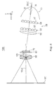
- Figure 7 is a general view showing the configuration of the principal parts of a projection display apparatus 10D that is a fourth embodiment.
- the projection display apparatus 10D has an illumination system 100, a color separator 200, an optical guide system 220, a reflecting mirror 218, three field lenses 240, 242 and 244, three liquid crystal devices 250, 252 and 254, a cross-dichroic prism 260 and a projection lens system 270.
- the liquid crystal devices 250, 252 and 254 are each the same as the second liquid crystal device 80B ( Figure 6). In the following, the liquid crystal devices are also referred to as light valves.
- the illumination system 100 includes a light source 110, a first lens array 120, a second lens array 130, a superposing lens 150 and a reflecting mirror 160. Except for the reflecting mirror 160, the illumination system 100 is the same as the illumination system 20. For convenience the reference numerals of the parts have been changed.
- the reflecting mirror 160 is provided to deflect the direction of the light. In terms of function, the illumination system is the same as the illumination system 20, so further description thereof is omitted.
- the color separator 200 has a pair of dichroic mirrors 210 and 212.
- the color separator 200 functions to separate a beam of illumination light from the illumination system 100 into three colors: red, green and blue.
- the first dichroic mirror 210 transmits red components in the light beam emitted by the illumination system 100 and reflects blue and green components. Red light transmitted by the dichroic mirror 210 is reflected by the reflecting mirror 218, directing the light through the field lens 240 and onto the light valve 250 for red light.
- the field lens 240 converts the partial light beams emitted by the second lens array 130 into a beam of light parallel to the center axis (principal beam) thereof. This is also the case with the field lenses 242 and 244 disposed in front of the other light valves.
- the green light is reflected by the second dichroic mirror 212 and is thereby directed to the light valve 252 for green light via the field lens 242.
- the blue light passes through the second dichroic mirror 212 and impinges on the optical guide system 220.
- the optical guide system 220 includes an entrance lens 230, a relay lens 232 and reflecting mirrors 222 and 224. Blue light transmitted by the second dichroic mirror 212 passes through the optical guide system (relay lens system) 220 and exit lens (field lens) 244 to the light valve 254 for blue light.
- the blue light path is longer than the light paths of the other colors, so the blue light path is provided with a relay lens system to prevent a decrease in the light utilization efficiency caused by light beam divergence and the like. That is, the relay lens system is to ensure that partial light beams that enter the entrance lens 230 are transmitted unchanged to the exit lens 244.
- the three light valves 250, 252 and 254 function as light modulator for forming images by modulating the light of each of the three colors according to supplied image information (image signals).
- the cross dichroic prism 260 functions as a color combiner for combining the red, blue and green light to form a color image.
- the cross dichroic prism 260 is formed by a multi-layer dielectric film stack 262 that reflects red light and a multi-layer dielectric film stack 264 that reflects blue light arranged in the form of a cross.
- the film stacks 262 and 264 are intersected by a center axis 266 that runs along the y axis.
- the three colors are combined by these multi-layer dielectric film stacks into light carrying the color image to be projected.
- the light combined by the cross dichroic prism 260 is emitted toward projection lens 270.
- the light thus combined by the cross dichroic prism 260 is projected on the screen SC by the projection lens 270 constituting the projection system to display
- the projection display apparatus 10D uses the same liquid crystal devices as the second liquid crystal device 80B described with reference to the third embodiment. This makes it possible to improve the contrast without much of a decrease in the brightness of the color image projected on the screen SC.
- the first liquid crystal device 80 ( Figure 3) may be used for the three light valves 250, 252 and 254. Doing so would enable the contrast of color images projected on the screen SC to be improved.
- the optical elements provided along each light path up to the plane of incidence of the three liquid crystal devices it is preferable for the optical elements provided along each light path up to the plane of incidence of the three liquid crystal devices to be arranged so that in each case the center of each beam of incident illumination light is parallel to the clear viewing direction. This will make it, possible to increase the contrast without much reduction in the brightness of the color images projected on the screen SC.
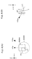
- Figures 8(A) and 8(B) are views illustrating the position relationship between micro-lens 830M and opening 826W in a liquid crystal device 80C according to a fifth embodiment.
- Figure 8 (A) is a view from the display surface side of the liquid crystal device 80C, that is, the side from which the light is emitted (along the z axis)
- Figure 8 (B) is a view from the side of the liquid crystal device 80C (along the x axis).
- the micro-lens 830M is positioned at an offset relative to the center axis of the corresponding opening 826W so that a line connecting center LC on the optical axis of the micro-lens 830M with center AC on the center axis of the opening 826W is substantially parallel to the clear viewing vector VD representing the clear viewing direction. That is, the micro-lens 830M is located at a position where the optical axis is out of alignment with the center axis of the opening 826W so as to be substantially parallel with the clear viewing direction vector VD in the xy plane, the vector components VDxy and VDyz in the yz plane.
- the micro-lens 830M is located at an offset relative to the center axis of the corresponding opening 826W whereby a line connecting center LC on the optical axis of the micro-lens 830M with center AC on the center axis of the opening 826W is moved in the negative y direction of the clear viewing direction vector component VDy. It is also located at an offset relative to the center axis of the opening 826W whereby the line becomes substantially parallel to VDyz, the clear viewing direction vector VD in the plane yz.
- Light valves 250E, 252E and 254E of a projection display apparatus 10E that is basically the same as the projection display apparatus 10D of the fourth embodiment will now be described.
- the light valves 250E, 252E and 254E are each constituted of a liquid crystal device 80C.
- Figure 9 is a diagram illustrating the incidence of illumination light on the light valve 252E used to handle green light.
- a beam of light from light source 110 is divided into a plurality of partial beams by first lens array 120.
- the light valve 252E is illuminated by these partial beams, via the superposing lens 150.
- the partial beams are converted by the field lens 242 into light beams parallel to the center axis of the partial beams.
- the partial beams emitted by the field lens 242 each have a different inclination relative to the optical axis 100LC that corresponds to the point on the first lens array 120 from which the beam exits.
- the intensity of the light from the light source 110 is generally stronger closer to the optical axis 100LC and weaker as the distance from the center increases.
- the intensity distribution of light relative to the direction of light incidence (hereinafter referred to as “angular distribution of the light”) may differ depending on the position of the light valve 252E.
- Figure 10 illustrates an example of the angular distribution of incident light on the light valve 252.
- the arrows indicate the direction of the light and the size of the arrows indicate the light intensity.
- the angular distribution of incident light in the vicinity of the center of the light valve 252 is substantially uniform, but as the distance from the center increases, the intensity of light oriented toward the center of the light valve tends to rise.
- Figures 11(A-1) through 11(B-2) are diagrams illustrating the contrast and the brightness of image displayed by the light valves 250, 252 and 254 of the projection display apparatus 10D, having the angular distribution of the incident light shown in figure 10.
- the light valves 250, 252 and 254 all use the same liquid crystal device 80.
- the contrast in the case of the light valve 252 used to handle green (G) differs depending on the position of the light valve pixel. That is, if the contrast in the center of the light valve is taken as Medium, it is High at the lower left and Low at the upper right. The upper left and lower right are also Medium. Also, when the red (R) light and blue (B) light valves 250 and 254 are illuminated and the green (G) light valve 252 is illuminated, left-right contrast levels become virtually reversed along the center axis of the light in the vertical direction (y axis).
- the brightness of light exiting the green light valve 252 can vary within the plane of the light valve, as shown by Figure 11 (B-1). That is, if the brightness in the vicinity of the center of the light valve is taken as Medium, the lower left is Bright and the upper right is Dark. Also, the upper left and lower right are Medium.
- the brightness of light exiting the red and blue light valves 250 and 254 shows the same characteristics as in the case of contrast. That is, in terms of left-and-right sides of the screens along the y axis, the brightness distribution of the red and blue light valves 250 and 254 is the opposite to that of the green light valve 252.
- the brightness in the lower left part of the green light valve 252 is Bright
- the brightness of the light at the lower left is Medium. This can result in non-uniformity of brightness and colors in images projected on the screen SC.
- Non-uniformity of brightness and colors can also arise during black screen display.
- the brightness distribution characteristics of the light valves 250, 252 and 254 during black screen display are opposite to those during white screen display. That is, a brightness level that is Bright during white screen display will be Dark during black screen display. Thus, the nature of the brightness and color non-uniformity arising during black screen display differs from that arising during white screen display.
- Figures 12(A-1) through 12(B-2) are diagrams illustrating the contrast and the brightness of image displayed by the light valves 250E, 252E and 254E of the projection display apparatus 10E, having the angular distribution of the incident light shown in figure 10.
- the light valves 250E, 252E and 254E all use the same liquid crystal device 80C.
- the micro-lenses 830M are offset only vertically, that is, only in a direction parallel to the center axis 266 of the cross dichroic prism 260 ( Figures 8(A) and 8(B)).
- the contrast distribution in the three light valves 250E, 252E and 254E can be reduced compared to the contrast distribution of the projection display apparatus 10D shown in Figures 11 (A-1) and 11(A-2). Moreover, virtually the same can be achieved with respect to contrast distribution laterally across the screens of the three light valves 250E, 252E and 254E, thereby making it possible to reduce contrast non-uniformity in the direction.
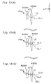
- Figures 13(A) through 13(C) are diagrams illustrating the positional relationship between the micro-lens 830M and opening 826W of a liquid crystal device 80D.
- the liquid crystal device 80D is shown from the side (along the x axis).
- the liquid crystal device 80D is divided into three pixel groups along direction y, each having a different positional relationship between micro-lens 830M and opening 826W.
- the micro-lens 830M is located at a position that relative to the center axis of the corresponding opening 826W is offset in a negative direction along the y axis so that a line DL1 connecting center LC on the optical axis of the micro-lens 830M with the center AC on the center axis of the opening 826W is substantially parallel to the vector component VDyz of the clear viewing direction vector VD in plane yz.
- the micro-lens 830M is located at a position that is offset from the center axis of the opening 826W so that a line DL2 connecting the center LC on the optical axis of the micro-lens 830M with the center AC on the center axis of the corresponding opening 826W is inclined more toward the z axis than the vector component VDyz.
- the micro-lens 830M is located at a position that is offset from the center axis of the corresponding opening 826W so that a line DL3 connecting the center LC on the optical axis of the micro-lens 830M with the center AC on the center axis of the opening 826W is inclined more toward the z axis than the line DL2 in the case of the middle pixel group.
- contrast and brightness of the three light valves 250E, 252E and 254E relative to the clear viewing direction (clear viewing vector) VD tend to be higher toward the lower side of the light valves and lower toward the upper side, contrast, brightness, and color non-uniformity distribution can be made more even as described in the above.
- micro-lens 830M being offset relative to the center axis of the opening 826W in the negative direction of y vector component VDy representing the clear viewing direction vector VD ( Figures 8 and 13).
- the micro-lens 830M can also be offset from the center axis of the opening 826W in the negative direction of the x vector component VDx. Doing this would still allow the contrast, brightness, and color non-uniformity distribution to be decreased.
- micro-lens 830M is to be offset relative to the center axis of the opening 826W in the negative direction of y vector component VDy representing the clear viewing direction vector VD or in the negative direction of the x vector component VDx, from the standpoint of contrast, it is preferable for the micro-lens 830M to be offset in the direction of whichever has a larger negative direction. While the above explanation was made with reference to the micro-lens 830M being offset along the cross dichroic prism center axis 266 in the direction of the x axis, in terms of uniformity of contrast, brightness and color, it is preferable for the micro-lens 830M to be offset in the negative direction of the clear viewing vector component VDx.
- the liquid crystal device 80D was described with reference to its division into three pixel groups in the direction of the y axis. However, it is to be understood that the invention is not limited thereto. Instead, the division into pixel groups as well as the positional relationships between micro-lens 830M and opening 826W can be adjusted according to the degree of change in the contrast or brightness of the light valves.
- the fifth embodiment was described using as an example a projection display apparatus that uses three liquid crystal devices 80C or 80D to display color images.
- the projection display apparatus can be configured using one liquid crystal device 80C or 80D, as in the first three embodiments. Such a configuration will still enable non-uniformity in the contrast, brightness or colors of the displayed images to be decreased.
- the apparatus may be equipped with a polarizing apparatus that is used to linearly polarize the light that is used.
- a polarizing apparatus that is used to linearly polarize the light that is used.
- Using linearly polarized light that can be transmitted by a polarization plate provided at the entrance to the liquid crystal device would make it possible to prevent light loss, thereby improving the light utilization efficiency of the projection display apparatus.
Landscapes
- Physics & Mathematics (AREA)
- Nonlinear Science (AREA)
- General Physics & Mathematics (AREA)
- Optics & Photonics (AREA)
- Mathematical Physics (AREA)
- Chemical & Material Sciences (AREA)
- Crystallography & Structural Chemistry (AREA)
- Liquid Crystal (AREA)
- Projection Apparatus (AREA)
- Devices For Indicating Variable Information By Combining Individual Elements (AREA)
- Illuminated Signs And Luminous Advertising (AREA)
Applications Claiming Priority (4)
| Application Number | Priority Date | Filing Date | Title |
|---|---|---|---|
| JP18689898 | 1998-06-16 | ||
| JP18689898 | 1998-06-16 | ||
| JP11025860A JP2000075259A (ja) | 1998-06-16 | 1999-02-03 | 液晶装置及びこれを用いた投写型表示装置 |
| JP2586099 | 1999-02-03 |
Publications (1)
| Publication Number | Publication Date |
|---|---|
| EP0965875A1 true EP0965875A1 (de) | 1999-12-22 |
Family
ID=26363548
Family Applications (1)
| Application Number | Title | Priority Date | Filing Date |
|---|---|---|---|
| EP99304610A Withdrawn EP0965875A1 (de) | 1998-06-16 | 1999-06-14 | Flüssigkristallvorrichtung sowie ein Projektionsanzeigegerät, welches eine solche Vorrichtung verwendet |
Country Status (6)
| Country | Link |
|---|---|
| US (1) | US6195143B1 (de) |
| EP (1) | EP0965875A1 (de) |
| JP (1) | JP2000075259A (de) |
| KR (1) | KR100562683B1 (de) |
| CN (1) | CN1165803C (de) |
| TW (1) | TW476928B (de) |
Cited By (2)
| Publication number | Priority date | Publication date | Assignee | Title |
|---|---|---|---|---|
| EP1146384A3 (de) * | 2000-04-10 | 2003-06-18 | Sony Corporation | Verfahren zur Bestimmung der Mikrolinsenposition für einen Flachbildschirm |
| EP3009882A3 (de) * | 2014-10-15 | 2016-05-11 | Seiko Epson Corporation | Elektrooptische anzeigevorrichtung |
Families Citing this family (12)
| Publication number | Priority date | Publication date | Assignee | Title |
|---|---|---|---|---|
| US6825889B1 (en) | 1998-11-30 | 2004-11-30 | Seiko Epson Corporation | Liquid crystal device with an offset toward a clear viewing direction and projection type display device using the liquid crystal device |
| US7002659B1 (en) * | 1999-11-30 | 2006-02-21 | Semiconductor Energy Laboratory Co., Ltd. | Liquid crystal panel and liquid crystal projector |
| KR100668391B1 (ko) * | 2000-02-26 | 2007-01-12 | 에스케이 텔레콤주식회사 | 댁내 상태보고 전화기 |
| US6421105B1 (en) * | 2001-04-24 | 2002-07-16 | Wintek Corporation | Optic device of high illumination reflecting type liquid crystal display |
| JP2002350823A (ja) * | 2001-05-28 | 2002-12-04 | Sony Corp | 液晶表示素子および投射型液晶表示装置 |
| JP2004012949A (ja) * | 2002-06-10 | 2004-01-15 | Canon Inc | 電気泳動表示装置 |
| US7012755B1 (en) * | 2003-02-14 | 2006-03-14 | Lightmaster Systems, Inc. | Use of a lens array to increase the contrast ratio produced by a LCoS microdisplay |
| CN100419493C (zh) * | 2005-01-19 | 2008-09-17 | 鸿富锦精密工业(深圳)有限公司 | 光开关及其制作方法 |
| US7486854B2 (en) * | 2006-01-24 | 2009-02-03 | Uni-Pixel Displays, Inc. | Optical microstructures for light extraction and control |
| JP6149339B2 (ja) * | 2010-06-16 | 2017-06-21 | 株式会社ニコン | 表示装置 |
| JP7151616B2 (ja) | 2019-05-09 | 2022-10-12 | セイコーエプソン株式会社 | 表示装置、および電子機器 |
| JP7006653B2 (ja) | 2019-05-09 | 2022-01-24 | セイコーエプソン株式会社 | 表示装置、および電子機器 |
Citations (4)
| Publication number | Priority date | Publication date | Assignee | Title |
|---|---|---|---|---|
| JPH02257119A (ja) * | 1989-03-30 | 1990-10-17 | Seiko Epson Corp | 液晶表示素子 |
| JPH04134321A (ja) * | 1990-09-26 | 1992-05-08 | Sanyo Electric Co Ltd | 液晶表示装置 |
| US5493427A (en) * | 1993-05-25 | 1996-02-20 | Sharp Kabushiki Kaisha | Three-dimensional display unit with a variable lens |
| EP0802685A2 (de) * | 1996-04-17 | 1997-10-22 | Hitachi, Ltd. | Einplatten-LCD Anzeigegerät |
Family Cites Families (11)
| Publication number | Priority date | Publication date | Assignee | Title |
|---|---|---|---|---|
| EP0534426B1 (de) * | 1991-09-26 | 1997-01-02 | Canon Kabushiki Kaisha | Flüssigkristallanzeige und damit versehener Projektor |
| JP2884458B2 (ja) * | 1992-05-11 | 1999-04-19 | キヤノン株式会社 | 液晶表示パネルの製造方法 |
| JP2942129B2 (ja) * | 1993-12-24 | 1999-08-30 | シャープ株式会社 | 投影型カラー液晶表示装置 |
| JP3344635B2 (ja) * | 1993-12-27 | 2002-11-11 | シャープ株式会社 | カラー液晶表示装置 |
| JP3086137B2 (ja) * | 1994-09-13 | 2000-09-11 | シャープ株式会社 | マイクロレンズ基板の製造方法および製造装置 |
| JP2951858B2 (ja) * | 1994-10-17 | 1999-09-20 | シャープ株式会社 | 投影型カラー液晶表示装置 |
| DE69627561T2 (de) * | 1995-02-10 | 2004-03-18 | Sharp K.K. | Projektionsbildanzeigevorrichtung |
| JP3318859B2 (ja) * | 1996-11-28 | 2002-08-26 | ソニー株式会社 | 液晶表示装置 |
| US5990992A (en) * | 1997-03-18 | 1999-11-23 | Nippon Sheet Glass Co., Ltd. | Image display device with plural planar microlens arrays |
| JPH11133372A (ja) * | 1997-10-28 | 1999-05-21 | Sony Corp | 液晶変調素子および投射型液晶表示装置 |
| JPH11231314A (ja) * | 1998-02-16 | 1999-08-27 | Micro Opt:Kk | 液晶表示素子 |
-
1999
- 1999-02-03 JP JP11025860A patent/JP2000075259A/ja not_active Withdrawn
- 1999-06-14 EP EP99304610A patent/EP0965875A1/de not_active Withdrawn
- 1999-06-14 US US09/332,441 patent/US6195143B1/en not_active Expired - Lifetime
- 1999-06-15 TW TW088109983A patent/TW476928B/zh not_active IP Right Cessation
- 1999-06-16 CN CNB991086252A patent/CN1165803C/zh not_active Expired - Fee Related
- 1999-06-16 KR KR1019990022624A patent/KR100562683B1/ko not_active Expired - Fee Related
Patent Citations (4)
| Publication number | Priority date | Publication date | Assignee | Title |
|---|---|---|---|---|
| JPH02257119A (ja) * | 1989-03-30 | 1990-10-17 | Seiko Epson Corp | 液晶表示素子 |
| JPH04134321A (ja) * | 1990-09-26 | 1992-05-08 | Sanyo Electric Co Ltd | 液晶表示装置 |
| US5493427A (en) * | 1993-05-25 | 1996-02-20 | Sharp Kabushiki Kaisha | Three-dimensional display unit with a variable lens |
| EP0802685A2 (de) * | 1996-04-17 | 1997-10-22 | Hitachi, Ltd. | Einplatten-LCD Anzeigegerät |
Non-Patent Citations (1)
| Title |
|---|
| PATENT ABSTRACTS OF JAPAN vol. 015, no. 011 (P - 1150) 10 January 1991 (1991-01-10) * |
Cited By (3)
| Publication number | Priority date | Publication date | Assignee | Title |
|---|---|---|---|---|
| EP1146384A3 (de) * | 2000-04-10 | 2003-06-18 | Sony Corporation | Verfahren zur Bestimmung der Mikrolinsenposition für einen Flachbildschirm |
| EP3009882A3 (de) * | 2014-10-15 | 2016-05-11 | Seiko Epson Corporation | Elektrooptische anzeigevorrichtung |
| US10139669B2 (en) | 2014-10-15 | 2018-11-27 | Seiko Epson Corporation | Electro-optical device and electronic instrument |
Also Published As
| Publication number | Publication date |
|---|---|
| US6195143B1 (en) | 2001-02-27 |
| KR20000006228A (ko) | 2000-01-25 |
| CN1239233A (zh) | 1999-12-22 |
| KR100562683B1 (ko) | 2006-03-23 |
| TW476928B (en) | 2002-02-21 |
| JP2000075259A (ja) | 2000-03-14 |
| CN1165803C (zh) | 2004-09-08 |
Similar Documents
| Publication | Publication Date | Title |
|---|---|---|
| EP0717865B1 (de) | Flüssigkristall-projektionsanzeigesysteme | |
| US6513953B1 (en) | Illumination system and projector | |
| US5757341A (en) | Color liquid crystal projection display systems | |
| JP3876929B2 (ja) | カラー表示装置 | |
| US6195143B1 (en) | Liquid crystal panel structure with micro-lens array and projector using the micro-lens array | |
| US6680762B2 (en) | Projection liquid crystal display apparatus wherein overall focal point of the lens is shifted to increase effective aperture ratio | |
| CN102103311B (zh) | 图像显示装置 | |
| KR100231979B1 (ko) | 표시장치, 액정표시패널 및 이를 사용한 투사형 표시장치 | |
| US6481852B2 (en) | Projector apparatus comprising a light composing optical system vertically stacked with respect to a light separation optical system | |
| KR19980042803A (ko) | 액정패널 및 이것을 사용한 투사형 표시장치 | |
| US11378878B2 (en) | Projector | |
| US6831707B2 (en) | Liquid crystal display element and projection type liquid crystal display device | |
| US6902276B2 (en) | Color projector apparatus and method | |
| KR100626343B1 (ko) | 투사형 표시장치 | |
| WO2006001183A1 (ja) | 液晶表示装置及び液晶表示層を用いた投射型表示装置 | |
| KR20050025904A (ko) | 화상투사장치 | |
| US6398365B1 (en) | Image projection display apparatus | |
| US7172293B2 (en) | Projector | |
| US5649752A (en) | Projector system using two liquid crystal projectors | |
| JP4333355B2 (ja) | 空間光変調装置及びプロジェクタ | |
| JP3633361B2 (ja) | 投写型液晶表示装置 | |
| JP3767709B2 (ja) | カラー画像表示装置の色調整方法 | |
| JP2002148617A (ja) | 液晶表示装置 | |
| US6896372B2 (en) | Off-axis image projecting system | |
| JP2000047137A (ja) | 反射型表示素子および投写型表示装置 |
Legal Events
| Date | Code | Title | Description |
|---|---|---|---|
| PUAI | Public reference made under article 153(3) epc to a published international application that has entered the european phase |
Free format text: ORIGINAL CODE: 0009012 |
|
| AK | Designated contracting states |
Kind code of ref document: A1 Designated state(s): DE FR GB |
|
| AX | Request for extension of the european patent |
Free format text: AL;LT;LV;MK;RO;SI |
|
| 17P | Request for examination filed |
Effective date: 20000417 |
|
| AKX | Designation fees paid |
Free format text: DE FR GB |
|
| 17Q | First examination report despatched |
Effective date: 20030514 |
|
| STAA | Information on the status of an ep patent application or granted ep patent |
Free format text: STATUS: THE APPLICATION IS DEEMED TO BE WITHDRAWN |
|
| 18D | Application deemed to be withdrawn |
Effective date: 20071114 |