EP0965981A2 - Dispositif d'exploration d'un support d'enregistrement optique - Google Patents
Dispositif d'exploration d'un support d'enregistrement optique Download PDFInfo
- Publication number
- EP0965981A2 EP0965981A2 EP99201868A EP99201868A EP0965981A2 EP 0965981 A2 EP0965981 A2 EP 0965981A2 EP 99201868 A EP99201868 A EP 99201868A EP 99201868 A EP99201868 A EP 99201868A EP 0965981 A2 EP0965981 A2 EP 0965981A2
- Authority
- EP
- European Patent Office
- Prior art keywords
- radiation beam
- radiation
- detection system
- detectors
- detector
- Prior art date
- Legal status (The legal status is an assumption and is not a legal conclusion. Google has not performed a legal analysis and makes no representation as to the accuracy of the status listed.)
- Withdrawn
Links
- 230000003287 optical effect Effects 0.000 title claims abstract description 19
- 230000005855 radiation Effects 0.000 claims abstract description 67
- 230000004075 alteration Effects 0.000 claims abstract description 29
- 238000011896 sensitive detection Methods 0.000 claims abstract description 6
- 238000001514 detection method Methods 0.000 claims description 33
- 206010010071 Coma Diseases 0.000 claims description 10
- 238000000034 method Methods 0.000 claims description 10
- 239000000969 carrier Substances 0.000 claims description 4
- 239000010410 layer Substances 0.000 description 38
- 238000005259 measurement Methods 0.000 description 9
- 201000009310 astigmatism Diseases 0.000 description 2
- 230000005540 biological transmission Effects 0.000 description 2
- 239000000758 substrate Substances 0.000 description 2
- 206010073261 Ovarian theca cell tumour Diseases 0.000 description 1
- 230000008878 coupling Effects 0.000 description 1
- 238000010168 coupling process Methods 0.000 description 1
- 238000005859 coupling reaction Methods 0.000 description 1
- 230000001934 delay Effects 0.000 description 1
- 230000009977 dual effect Effects 0.000 description 1
- 230000000694 effects Effects 0.000 description 1
- 230000007613 environmental effect Effects 0.000 description 1
- 238000007654 immersion Methods 0.000 description 1
- 230000005415 magnetization Effects 0.000 description 1
- 238000000691 measurement method Methods 0.000 description 1
- 230000000737 periodic effect Effects 0.000 description 1
- 239000011241 protective layer Substances 0.000 description 1
- 210000001747 pupil Anatomy 0.000 description 1
- 239000004065 semiconductor Substances 0.000 description 1
- 239000007787 solid Substances 0.000 description 1
- 238000001228 spectrum Methods 0.000 description 1
- 208000001644 thecoma Diseases 0.000 description 1
Images


Classifications
-
- G—PHYSICS
- G11—INFORMATION STORAGE
- G11B—INFORMATION STORAGE BASED ON RELATIVE MOVEMENT BETWEEN RECORD CARRIER AND TRANSDUCER
- G11B7/00—Recording or reproducing by optical means, e.g. recording using a thermal beam of optical radiation by modifying optical properties or the physical structure, reproducing using an optical beam at lower power by sensing optical properties; Record carriers therefor
- G11B7/24—Record carriers characterised by shape, structure or physical properties, or by the selection of the material
- G11B7/2407—Tracks or pits; Shape, structure or physical properties thereof
- G11B7/24085—Pits
-
- G—PHYSICS
- G11—INFORMATION STORAGE
- G11B—INFORMATION STORAGE BASED ON RELATIVE MOVEMENT BETWEEN RECORD CARRIER AND TRANSDUCER
- G11B7/00—Recording or reproducing by optical means, e.g. recording using a thermal beam of optical radiation by modifying optical properties or the physical structure, reproducing using an optical beam at lower power by sensing optical properties; Record carriers therefor
- G11B7/08—Disposition or mounting of heads or light sources relatively to record carriers
- G11B7/09—Disposition or mounting of heads or light sources relatively to record carriers with provision for moving the light beam or focus plane for the purpose of maintaining alignment of the light beam relative to the record carrier during transducing operation, e.g. to compensate for surface irregularities of the latter or for track following
- G11B7/0908—Disposition or mounting of heads or light sources relatively to record carriers with provision for moving the light beam or focus plane for the purpose of maintaining alignment of the light beam relative to the record carrier during transducing operation, e.g. to compensate for surface irregularities of the latter or for track following for focusing only
- G11B7/0917—Focus-error methods other than those covered by G11B7/0909 - G11B7/0916
Definitions
- the invention relates to a device for scanning a surface comprising optically detectable marks along a scan line, which device comprises a radiation source for emitting a radiation beam, an objective system for guiding the radiation beam to the surface, a radiation-sensitive detection system for receiving radiation from the surface and an electronic circuit for processing output signals of the detection system.
- optical aberrations has recently become relevant in the field of optical recording, in particular the measurement of spherical aberration.
- the information density on optical record carriers may be increased by increasing the numerical aperture (NA) of the radiation beam used for reading and writing information on the record carrier.
- NA numerical aperture
- the record carriers are often scanned through a transparent layer protecting the information layer of the record carrier.
- a small variation of the thickness of the transparent layer causes a substantial change in the spherical aberration incurred by a high-numerical aperture radiation beam traversing the transparent layer. This spherical aberration may be reduced by using a dual lens objective system.
- Such a system has a first lens and a second lens, the second lens being a plano-convex lens arranged between the first and lens and the record carrier, and a small spacing between the plano surface and the record carrier.
- the plano-convex lens is referred to as a solid immersion lens.
- the article "High density optical disk system using a new two-element lens and a thin substrate disk" by F. Maeda et al, published in the proceedings of ISOM96 p. 342-344 discloses an optical recording system having such a dual-lens objective system.
- the spherical aberration due to variations in the thickness of the transparent layer are compensated by changing the axial position of the plano-convex lens of the objective system.
- the system determines the spherical aberration in the beam reflected from the record carrier and uses this value to position the plano-convex lens.
- the spherical aberration is determined from the shape of the focus error signal as a function of the focus error.
- the axial position of the plano-convex lens is optimized to obtain the desired shape.
- the method has as a disadvantage that the shape of the focus error signal as a function of the focus position must be analysed, which requires wobbling the objective system through the point of best focus. During wobbling the reading and writing performance of the optical disk system is reduced.
- a device as described in the preamble which device is characterized according to the invention in that the detection system comprises a plurality of detectors, each detector having an output for providing a detector signal, and in that the device comprises an electronic circuit for forming a time difference between corresponding parts of the detector signals relating to passage of the radiation beam over one of the marks and for generating from the time difference a signal representing a wavefront aberration of the radiation beam.
- the invention is based on the insight that different rays within the radiation beam will behave differently when the wavefront of the radiation beam deviates from the shape required for forming a proper focal spot on the surface. Such a deviation occurs when the beam is affected by optical aberrations.
- the position at which a ray is incident on the surface or information layer depends on the position of the ray in the pupil of the beam.
- a ray which impinges on the information layer ahead of the central part of the focal spot will experience the presence of a mark in the layer earlier than the rays forming the central part of the focal spot. It turns out that a suitable division of the detection system in detectors allows measurement of the time difference between the rays coming from the surface.
- the different detectors will determine different passage times for leading and trailing edges of the marks.
- a measurement of the time difference between the detector output signals of the occurrence of a particular feature of the surface, such as a leading or trailing edge of a mark, allows a determination of the primary optical aberrations.
- the second object of the invention is met by a device as described in the preamble, which device is characterized according to the invention in that the detection system comprises eight detectors arranged in four quadrants, each quadrant being split at a radius in an inner part and an outer part, each detector having an output for providing a detector signal, and in that the device comprises an electronic circuit for forming a time difference between corresponding parts of the detector signals relating to passage of the radiation beam over one of the marks and for generating from the time difference a focus error signal.
- the wavefront of the beam must deviate from spherical in a plane containing both the axis of the beam and the scan line in order to measure non-zero time differences.
- Defocus, spherical aberration and tangential coma are examples of wavefront deviations that can be measured when scanning along the scan line.
- Other wavefront deviations, such as transverse coma can be determined by the same method if the focal spot is wobbled in a direction transverse to the scan line and the detection system has a dividing line substantially parallel to the scan line. A measurement of the defocus in two directions allows the determination of the value of astigmatism.
- the invention further relates to a method for determining the focus error and the optical aberrations from a time or phase measurement.
- the invention also relates to a record carrier having specific patterns of marks located at specified parts of the tracks.
- Figure 1A shows an unaberrated wavefront 1 of a radiation beam and a wavefront 2 aberrated by coma.
- Rays of the unaberrated wavefront indicated in the Figure by drawn lines, intercept a surface 3 in point 4 when the radiation beam is properly focussed on the surface.
- Rays 5, 6, 7 and 8 of the comatic wavefront indicated by dashed lines, intercept the surface at different points 9, 10, 10, 9, respectively, depending on the slope of the part of the wavefront pertaining to a ray.
- FIG. 1B shows a situation similar to the one of Figure 1A, wherein the radiation beam suffers from spherical aberration instead of coma.
- FIG. 2 shows a device for scanning a surface in the form of an optical record carrier 21, in which device the measurement method of aberration according to the invention has been implemented.
- the record carrier comprises a transparent layer 22, on one side of which an information layer 23 is arranged.
- the side of the information layer facing away from the transparent layer is protected from environmental influences by a protection layer 24.
- the side of the transparent layer facing the device is called the entrance face 25.
- the transparent layer 22 acts as a substrate for the record carrier by providing mechanical support for the information layer.
- the transparent layer may have the sole function of protecting the information layer and have a thickness in the range from 100 nm to 100 ⁇ m, or the transparent layer may be absent altogether.
- the mechanical support function for the record carrier is taken over by protective layer 24 or by a further information layer and transparent layer connected to the information layer 23.
- Information may be stored in the information layer 23 of the record carrier in the form of optically detectable marks arranged in substantially parallel, concentric or spiral tracks, not indicated in the Figure.
- the marks may be in any optically readable form, e.g. in the form of pits, or areas with a reflection coefficient or a direction of magnetization different from their surroundings, or a combination of these forms.
- the scanning device comprises a radiation source 26, for example a semi-conductor laser, emitting a diverging radiation beam 27.
- the lens system comprises a collimator lens 29, and an objective system comprising a first lens 30 and a second lens 31.
- Collimator lens 29 changes the diverging radiation beam 27 to a collimated beam 32.
- First lens 30, having an optical axis 33 transforms collimated radiation beam 32 into a converging beam 34 incident on lens 31.
- Collimator lens 29 and first lens 30 may be combined into a single lens.
- Second lens 31 changes incident beam 34 into a converging beam 35, which comes to a focus spot 36 on information layer 23.
- Second lens 31 in the embodiment of the Figure is a plano-convex lens. Its planar surface faces transparent layer 22 and forms a gap between the lens and the layer. The planar surface may have an aspherical profile to compensate for optical aberrations.
- objective lens 30 is indicated in the Figure as a single lens element, it may comprise more elements, and may also comprise a hologram operating in transmission or reflection, or a grating for coupling radiation out of a waveguide carrying the radiation beam. Radiation of converging beam 35 reflected by information layer 23 forms a reflected beam 37, which returns on the optical path of forward converging beam 34.
- First lens 30 and collimator lens 29 transform reflected beam 37 to a converging reflected beam 38, and beam splitter 28 separates the forward and reflected beams by transmitting at least part of reflected beam 38 towards a detection system 39.
- the detection system captures the radiation and converts it into one or more electrical detector signals 40.
- the detector signals are processed in an electronic circuit 41 in order to derive various signals from them.
- One of these signals is an information signal 42, the value of which represents the information read from the information layer 23.
- Another signal is a focus error signal, the value of which represents the axial difference in height between focus spot 36 and information layer 23.
- the focus error signal is used as input for a servo controller 43, which controls the positions of first lens 30 and/or second lens 31, thereby controlling the axial and transverse position of focus 36 spot such that it coincides substantially with the plane of information layer 23 and the centre of tracks on record carrier 21 to be followed by focus spot 36.
- Beam splitter 28 may also be a grating, which passes in transmission radiation beam 27 from radiation source 26, and deflects part of reflected beam 38 towards detection system 39.
- radiation source 26 and detection system 39 may be arranged close together on one side of the grating.
- Detection system 39 is arranged in the far field of information layer 23, i.e. the detection system is located in a plane where the various diffraction orders of the beam from the information layer are sufficiently separated, in other words, in a plane which is disposed sufficiently far from the image of the information layer formed by objective system 30, 31 and collimator lens 29.
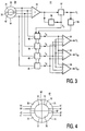
- Figure 2 shows a plan view of the detection system.
- the detection system comprises two concentric detectors split along a dividing line 50, giving two inner detectors 51, 52, and two outer detectors 53 and 54.
- the direction of the dividing line is perpendicular to the effective track direction.
- the effective track direction is the direction of the track currently being scanned on the record carrier as seen on the detection system through the optics between the detection system and the information layer comprising the track.
- the diameter of the inner detectors depends on the radius of the spot formed by radiation beam 38 on the detector surface. The diameter is preferably in a range from 50% to 80% of the spot diameter, and more preferably about 70%.
- Figure 3 also shows part of electronic circuit 41 for deriving aberration signals from the detector signals.
- the detector signals are connected to an adder 55, giving an output signal representing the total radiation intensity incident on detection system 39, and thereby the information stored in the marks of the record carrier.
- a clock extractor 56 in the form of a phase-locked loop, derives a clock signal S c from the output signal of adder 55.
- the clock signal is used in a circuit 57, which recovers the high-frequency or binary information signal S i from the output signal of adder 55.
- Clock signal S c is fed into timing units 58, 59, 60 and 61.
- Timing unit 58 determines the time difference t a between a leading edge of a mark in the signal from detector 53 and the corresponding edge of the clock signal.
- timing units 59, 60 and 61 determine the time differences t b , t c and t d between a leading edge of the same mark in the signal from detectors 52, 53 and 54, respectively, and the same edge of the clock signal S c .
- a circuit 62 combines the output signals of timing units 58 to 61 and forms a signal S ab equal t a - t b - t c + t d , representing the spherical aberration in the radiation beam.
- a circuit 63 also combines the output signals of timing units 58 to 61 and forms a signal S co equal t a - t b + t c - t d , representing the coma in the radiation beam.
- a circuit 64 forms a signal S f from the output signals of timing circuits 58 to 61, which signal is equal to t a + t b - t c - t d , representing the focus error, i.e. the axial distance between focus spot 36 and information layer 23.
- the output signals of circuit 41 may have a small offset, which can be compensated for in practice by tuning focus, spherical aberration and coma for minimum jitter in information signal S i .
- Circuit 10 may select particular patterns on the record carrier having advantageous properties.
- An example of a special pattern is one that is in phase with identical patterns in neighbouring tracks. The reading of such patterns is not affected by low-frequency cross-talk from the neighbouring tracks.
- the patterns are present in headers of sectors dividing the information layer in small storage units.
- circuit 10 selects patterns having marks with periods of approximately ⁇ /NA and 3 ⁇ /NA from the spectrum of patterns obtained when reading information from the record carrier and use these patterns for the determination of the signals S ab , S co and S f .
- the electronic circuit comprises a circuit 65, that establishes an enabling signal for timing units 58, 59, 60 and 61 from information signal S i.
- the record carrier for this player comprises, at specified locations, two patterns of marks at two different spatial frequencies.
- Circuit 65 sends an enabling signal to the timer units when the radiation beam is at the specified locations.
- Circuits 62, 63 and 64 are modified each to form two differences of the outputs of the timing units, one for each of the two patterns.
- the focus error and aberration signals may also be formed by determining the time difference between each of the four outputs of detectors 51, 52, 53 and 54 and subsequently making the required combination of the time differences.
- the focus error signal may also be obtained through measurement of phase differences between the detector signals and the clock signal or between the detector signals themselves.
- Figure 4 shows another embodiment 67 of the detection system.
- the detection system has two perpendicular dividing lines 68 and 69 and a circular dividing line 70.
- Dividing line 69 is parallel to the effective track direction. Alternatively, dividing line 69 may be rotated over 45°.
- the diameter of the circular line is similar to the one of detection system 39.
- the outer part of the detection system comprises four detectors 71 to 74, having detector signals a1 to d1.
- the inner part of the detection system comprises also four detectors 75 to 78, having detector signals a2 to d2.
- the time differences between the detector signals can be determined in the same way as for the detector signals in the embodiment shown in Figure 3.
- the slope of the delay in units of ⁇ /NA, corresponding to signal S sa , as a function of the value of the spherical aberration in units of ⁇ rms OPD in the radiation beam is approximately equal to 4/NA.
- the focus error signal S f derived according to the above equation is relatively insensitive to differences between record carriers of different type. A comparison of the time differences at two distinct spatial frequencies is not needed.
- the wavefront of the beam must deviate from spherical in a plane containing both the axis of the beam and the scan line in order to measure non-zero time differences.
- Defocus, spherical aberration and tangential coma are examples of wavefront deviations that can be measured when scanning along the scan line.
- Other wavefront deviations, such as transverse coma can be determined by the same method if the focal spot is wobbled in a direction transverse to the scan line and the detection system has a dividing line substantially parallel to the scan line.
- a radial wobble of the radiation beam may be effected by injecting a wobble signal in the part of servo circuit 43 controlling the radial servo.
- the detector signals should be connected to the timing units in a way corresponding to the different direction of motion. A measurement of the defocus in two directions allows the determination of the value of astigmatism
- FIG 5A shows a top view of a record carrier according to the invention, which is particularly suitable for use by a device comprising an electronic circuit as shown in Figure 3.
- the tracks along which the device scans the information are circular or spiral. Only one track 26 is shown in the Figure.
- Figure 5B shows an enlargement of part of track 26.
- each track comprises a pattern of marks having a spatial frequency in the range from 0.35 to 0.5 times the cut-off frequency of the objective system.
- each track comprises a pattern of marks having a spatial frequency in the range from 0.14 to 0.2 times the cut-off frequency.
- the patterns preferably have a period of 3 ⁇ /NA and 1 ⁇ /NA.
- the patterns in neighbouring tracks are preferably in phase.
- the patterns may form part of headers in which address information is stored.
- the patterns may form so-called VFO fields, i.e. fields used for generating a periodic signal to lock an oscillator to.
- the device should preferably derive a focus error signal from the low-frequency components of the detector signals, which has a substantially larger capture range.
- the low-frequency-derived focus error signal is used, and close to the information layer, servo circuit 11 gradually switches over to the high-frequency derived focus error signal.
- European patent application no. 812 457 describes several ways to derive a focus error signal from the low-frequency components of the detector signals and implementations of the gradual switch-over.
- the radial tracking error signal S r may be derived in known ways. Preferred methods are the push-pull method, known from inter alia US patent no. 4,057,833, and the differential time detection method, disclosed in US patent no. 4,785,441.
Landscapes
- Optical Recording Or Reproduction (AREA)
- Mechanical Optical Scanning Systems (AREA)
Priority Applications (1)
| Application Number | Priority Date | Filing Date | Title |
|---|---|---|---|
| EP99201868A EP0965981A3 (fr) | 1998-06-16 | 1999-06-11 | Dispositif d'exploration d'un support d'enregistrement optique |
Applications Claiming Priority (3)
| Application Number | Priority Date | Filing Date | Title |
|---|---|---|---|
| EP98202015 | 1998-06-16 | ||
| EP98202015 | 1998-06-16 | ||
| EP99201868A EP0965981A3 (fr) | 1998-06-16 | 1999-06-11 | Dispositif d'exploration d'un support d'enregistrement optique |
Publications (2)
| Publication Number | Publication Date |
|---|---|
| EP0965981A2 true EP0965981A2 (fr) | 1999-12-22 |
| EP0965981A3 EP0965981A3 (fr) | 2009-11-25 |
Family
ID=26150445
Family Applications (1)
| Application Number | Title | Priority Date | Filing Date |
|---|---|---|---|
| EP99201868A Withdrawn EP0965981A3 (fr) | 1998-06-16 | 1999-06-11 | Dispositif d'exploration d'un support d'enregistrement optique |
Country Status (1)
| Country | Link |
|---|---|
| EP (1) | EP0965981A3 (fr) |
Cited By (1)
| Publication number | Priority date | Publication date | Assignee | Title |
|---|---|---|---|---|
| EP1205923A3 (fr) * | 2000-11-09 | 2006-11-02 | Nec Corporation | Disque optique, procédé de correction d'aberration et appareil de disque optique |
Family Cites Families (7)
| Publication number | Priority date | Publication date | Assignee | Title |
|---|---|---|---|---|
| US4010317A (en) * | 1972-03-29 | 1977-03-01 | U.S. Philips Corporation | Apparatus for reading a record carrier in which information, for example video and/or audio information, is recorded in at least one track |
| NL7600843A (nl) * | 1976-01-28 | 1977-08-01 | Philips Nv | Inrichting voor het uitlezen van een registratie- drager waarop informatie, bijvoorbeeld en/of ge- luidsinformatie, is aangebracht. |
| NL7805069A (nl) * | 1978-05-11 | 1979-11-13 | Philips Nv | Inrichting voor puntsgewijze aftasting van een infor- matievlak. |
| JP2735220B2 (ja) * | 1987-12-02 | 1998-04-02 | 株式会社日立製作所 | 非点収差を有する光束を用いた焦点ずれ検出方法及び光ディスク装置 |
| KR940001999B1 (ko) * | 1989-06-06 | 1994-03-12 | 샤프 가부시끼가이샤 | 광 픽업장치 |
| JP3447135B2 (ja) * | 1995-02-02 | 2003-09-16 | パイオニア株式会社 | 情報再生装置 |
| EP1034537A2 (fr) * | 1998-06-15 | 2000-09-13 | Koninklijke Philips Electronics N.V. | Dispositif de balayage d'un support d'enregistrement optique |
-
1999
- 1999-06-11 EP EP99201868A patent/EP0965981A3/fr not_active Withdrawn
Cited By (1)
| Publication number | Priority date | Publication date | Assignee | Title |
|---|---|---|---|---|
| EP1205923A3 (fr) * | 2000-11-09 | 2006-11-02 | Nec Corporation | Disque optique, procédé de correction d'aberration et appareil de disque optique |
Also Published As
| Publication number | Publication date |
|---|---|
| EP0965981A3 (fr) | 2009-11-25 |
Similar Documents
| Publication | Publication Date | Title |
|---|---|---|
| KR100392857B1 (ko) | 기록 매체를 광학적으로 주사하기 위한 장치 | |
| US4730295A (en) | Apparatus for reading and/or recording a trackwise arranged optical information structure | |
| EP0943112B1 (fr) | Systeme de detection d'aberration spherique et dispositif optique utilisant celui-ci | |
| USRE38943E1 (en) | Compound objective lens for optical disks having different thicknesses | |
| KR880001707B1 (ko) | 광전자 집속에러 검출장치 | |
| KR100452904B1 (ko) | 광픽업장치,광픽업용대물렌즈,광픽업용집광광학계및광디스크장치 | |
| KR100704731B1 (ko) | 광학 주사장치 | |
| KR100292478B1 (ko) | 대물렌즈 | |
| JP3879897B2 (ja) | 光ピックアップ装置 | |
| US7298676B2 (en) | Optical pickup apparatus having optical detection area for compensating for tracking error offset | |
| JPH06176381A (ja) | 光学式情報記録再生装置 | |
| US6781104B1 (en) | Device for scanning an optical record carrier | |
| EP1115111B1 (fr) | Tête optique | |
| EP0831470B1 (fr) | Dispositif d'enregistrement ou de reproduction pour l'enregistrement ou la reproduction d'un support d'enregistrement optique | |
| EP0965981A2 (fr) | Dispositif d'exploration d'un support d'enregistrement optique | |
| US6788644B1 (en) | Devuce and method for forming a focus error signal based on ohase difference between corresponding parts of detector signals | |
| JP3044667B2 (ja) | 光学式読取り装置 | |
| EP1005031A2 (fr) | Lecteur multifaisceaux à réglage convenable de la distance entre la lentille d'objectif et le support d'enregistrement optique d'information | |
| JP3455399B2 (ja) | 光ディスク用センサシステム | |
| EP1067532B1 (fr) | Tête de lecture optique et appareil de disque optique | |
| US20070247984A1 (en) | Optical Record Carrier and Optical Scanning Device | |
| JP3879896B2 (ja) | 光ピックアップ装置及び焦点誤差検出方法 | |
| US7622696B2 (en) | Optical head device, optical information recording/reproducing apparatus and operation method of optical information recording/reproducing apparatus | |
| KR0144510B1 (ko) | 다중 포커싱이 가능한 광 픽업장치 | |
| EP0910070A2 (fr) | Appareil d'enregistrement / de reproduction optique d'information |
Legal Events
| Date | Code | Title | Description |
|---|---|---|---|
| PUAI | Public reference made under article 153(3) epc to a published international application that has entered the european phase |
Free format text: ORIGINAL CODE: 0009012 |
|
| AK | Designated contracting states |
Kind code of ref document: A2 Designated state(s): AT BE CH CY DE DK ES FI FR GB GR IE IT LI LU MC NL PT SE |
|
| AX | Request for extension of the european patent |
Free format text: AL;LT;LV;MK;RO;SI |
|
| XX | Miscellaneous (additional remarks) |
Free format text: AN APPEAL (ART. 109) FILED IN THE PRIORITY APPLICATION EP 98202015.8 AGAINST THE REJECTION OF THE APPLICANT'S REQUEST TO ACCORD 15.06.1998 AS THE DATE OF FILING IS PENDING. |
|
| PUAL | Search report despatched |
Free format text: ORIGINAL CODE: 0009013 |
|
| AK | Designated contracting states |
Kind code of ref document: A3 Designated state(s): AT BE CH CY DE DK ES FI FR GB GR IE IT LI LU MC NL PT SE |
|
| AX | Request for extension of the european patent |
Extension state: AL LT LV MK RO SI |
|
| AKX | Designation fees paid | ||
| REG | Reference to a national code |
Ref country code: DE Ref legal event code: 8566 |
|
| STAA | Information on the status of an ep patent application or granted ep patent |
Free format text: STATUS: THE APPLICATION IS DEEMED TO BE WITHDRAWN |
|
| 18D | Application deemed to be withdrawn |
Effective date: 20100526 |