EP0966051B1 - Système de batteries pour véhicules spatiaux - Google Patents
Système de batteries pour véhicules spatiaux Download PDFInfo
- Publication number
- EP0966051B1 EP0966051B1 EP19990304639 EP99304639A EP0966051B1 EP 0966051 B1 EP0966051 B1 EP 0966051B1 EP 19990304639 EP19990304639 EP 19990304639 EP 99304639 A EP99304639 A EP 99304639A EP 0966051 B1 EP0966051 B1 EP 0966051B1
- Authority
- EP
- European Patent Office
- Prior art keywords
- battery
- spacecraft
- mounting panel
- mounting
- cells
- Prior art date
- Legal status (The legal status is an assumption and is not a legal conclusion. Google has not performed a legal analysis and makes no representation as to the accuracy of the status listed.)
- Expired - Lifetime
Links
Images


Classifications
-
- B—PERFORMING OPERATIONS; TRANSPORTING
- B64—AIRCRAFT; AVIATION; COSMONAUTICS
- B64G—COSMONAUTICS; VEHICLES OR EQUIPMENT THEREFOR
- B64G1/00—Cosmonautic vehicles
- B64G1/22—Parts of, or equipment specially adapted for fitting in or to, cosmonautic vehicles
- B64G1/42—Arrangements or adaptations of power supply systems
- B64G1/425—Power storage
-
- B—PERFORMING OPERATIONS; TRANSPORTING
- B64—AIRCRAFT; AVIATION; COSMONAUTICS
- B64G—COSMONAUTICS; VEHICLES OR EQUIPMENT THEREFOR
- B64G1/00—Cosmonautic vehicles
- B64G1/22—Parts of, or equipment specially adapted for fitting in or to, cosmonautic vehicles
- B64G1/46—Arrangements or adaptations of devices for control of environment or living conditions
- B64G1/50—Arrangements or adaptations of devices for control of environment or living conditions for temperature control
- B64G1/503—Radiator panels
-
- B—PERFORMING OPERATIONS; TRANSPORTING
- B64—AIRCRAFT; AVIATION; COSMONAUTICS
- B64G—COSMONAUTICS; VEHICLES OR EQUIPMENT THEREFOR
- B64G1/00—Cosmonautic vehicles
- B64G1/22—Parts of, or equipment specially adapted for fitting in or to, cosmonautic vehicles
- B64G1/46—Arrangements or adaptations of devices for control of environment or living conditions
- B64G1/50—Arrangements or adaptations of devices for control of environment or living conditions for temperature control
- B64G1/506—Heat pipes
-
- H—ELECTRICITY
- H01—ELECTRIC ELEMENTS
- H01M—PROCESSES OR MEANS, e.g. BATTERIES, FOR THE DIRECT CONVERSION OF CHEMICAL ENERGY INTO ELECTRICAL ENERGY
- H01M10/00—Secondary cells; Manufacture thereof
- H01M10/60—Heating or cooling; Temperature control
- H01M10/61—Types of temperature control
- H01M10/613—Cooling or keeping cold
-
- H—ELECTRICITY
- H01—ELECTRIC ELEMENTS
- H01M—PROCESSES OR MEANS, e.g. BATTERIES, FOR THE DIRECT CONVERSION OF CHEMICAL ENERGY INTO ELECTRICAL ENERGY
- H01M10/00—Secondary cells; Manufacture thereof
- H01M10/60—Heating or cooling; Temperature control
- H01M10/61—Types of temperature control
- H01M10/617—Types of temperature control for achieving uniformity or desired distribution of temperature
-
- H—ELECTRICITY
- H01—ELECTRIC ELEMENTS
- H01M—PROCESSES OR MEANS, e.g. BATTERIES, FOR THE DIRECT CONVERSION OF CHEMICAL ENERGY INTO ELECTRICAL ENERGY
- H01M10/00—Secondary cells; Manufacture thereof
- H01M10/60—Heating or cooling; Temperature control
- H01M10/62—Heating or cooling; Temperature control specially adapted for specific applications
- H01M10/627—Stationary installations, e.g. power plant buffering or backup power supplies
-
- H—ELECTRICITY
- H01—ELECTRIC ELEMENTS
- H01M—PROCESSES OR MEANS, e.g. BATTERIES, FOR THE DIRECT CONVERSION OF CHEMICAL ENERGY INTO ELECTRICAL ENERGY
- H01M10/00—Secondary cells; Manufacture thereof
- H01M10/60—Heating or cooling; Temperature control
- H01M10/65—Means for temperature control structurally associated with the cells
- H01M10/655—Solid structures for heat exchange or heat conduction
- H01M10/6551—Surfaces specially adapted for heat dissipation or radiation, e.g. fins or coatings
-
- H—ELECTRICITY
- H01—ELECTRIC ELEMENTS
- H01M—PROCESSES OR MEANS, e.g. BATTERIES, FOR THE DIRECT CONVERSION OF CHEMICAL ENERGY INTO ELECTRICAL ENERGY
- H01M10/00—Secondary cells; Manufacture thereof
- H01M10/60—Heating or cooling; Temperature control
- H01M10/65—Means for temperature control structurally associated with the cells
- H01M10/655—Solid structures for heat exchange or heat conduction
- H01M10/6552—Closed pipes transferring heat by thermal conductivity or phase transition, e.g. heat pipes
-
- H—ELECTRICITY
- H01—ELECTRIC ELEMENTS
- H01M—PROCESSES OR MEANS, e.g. BATTERIES, FOR THE DIRECT CONVERSION OF CHEMICAL ENERGY INTO ELECTRICAL ENERGY
- H01M50/00—Constructional details or processes of manufacture of the non-active parts of electrochemical cells other than fuel cells, e.g. hybrid cells
- H01M50/20—Mountings; Secondary casings or frames; Racks, modules or packs; Suspension devices; Shock absorbers; Transport or carrying devices; Holders
- H01M50/204—Racks, modules or packs for multiple batteries or multiple cells
- H01M50/207—Racks, modules or packs for multiple batteries or multiple cells characterised by their shape
- H01M50/213—Racks, modules or packs for multiple batteries or multiple cells characterised by their shape adapted for cells having curved cross-section, e.g. round or elliptic
-
- H—ELECTRICITY
- H01—ELECTRIC ELEMENTS
- H01M—PROCESSES OR MEANS, e.g. BATTERIES, FOR THE DIRECT CONVERSION OF CHEMICAL ENERGY INTO ELECTRICAL ENERGY
- H01M50/00—Constructional details or processes of manufacture of the non-active parts of electrochemical cells other than fuel cells, e.g. hybrid cells
- H01M50/20—Mountings; Secondary casings or frames; Racks, modules or packs; Suspension devices; Shock absorbers; Transport or carrying devices; Holders
- H01M50/249—Mountings; Secondary casings or frames; Racks, modules or packs; Suspension devices; Shock absorbers; Transport or carrying devices; Holders specially adapted for aircraft or vehicles, e.g. cars or trains
-
- H—ELECTRICITY
- H01—ELECTRIC ELEMENTS
- H01M—PROCESSES OR MEANS, e.g. BATTERIES, FOR THE DIRECT CONVERSION OF CHEMICAL ENERGY INTO ELECTRICAL ENERGY
- H01M50/00—Constructional details or processes of manufacture of the non-active parts of electrochemical cells other than fuel cells, e.g. hybrid cells
- H01M50/20—Mountings; Secondary casings or frames; Racks, modules or packs; Suspension devices; Shock absorbers; Transport or carrying devices; Holders
- H01M50/289—Mountings; Secondary casings or frames; Racks, modules or packs; Suspension devices; Shock absorbers; Transport or carrying devices; Holders characterised by spacing elements or positioning means within frames, racks or packs
- H01M50/291—Mountings; Secondary casings or frames; Racks, modules or packs; Suspension devices; Shock absorbers; Transport or carrying devices; Holders characterised by spacing elements or positioning means within frames, racks or packs characterised by their shape
-
- H—ELECTRICITY
- H01—ELECTRIC ELEMENTS
- H01M—PROCESSES OR MEANS, e.g. BATTERIES, FOR THE DIRECT CONVERSION OF CHEMICAL ENERGY INTO ELECTRICAL ENERGY
- H01M10/00—Secondary cells; Manufacture thereof
- H01M10/34—Gastight accumulators
- H01M10/345—Gastight metal hydride accumulators
-
- Y—GENERAL TAGGING OF NEW TECHNOLOGICAL DEVELOPMENTS; GENERAL TAGGING OF CROSS-SECTIONAL TECHNOLOGIES SPANNING OVER SEVERAL SECTIONS OF THE IPC; TECHNICAL SUBJECTS COVERED BY FORMER USPC CROSS-REFERENCE ART COLLECTIONS [XRACs] AND DIGESTS
- Y02—TECHNOLOGIES OR APPLICATIONS FOR MITIGATION OR ADAPTATION AGAINST CLIMATE CHANGE
- Y02E—REDUCTION OF GREENHOUSE GAS [GHG] EMISSIONS, RELATED TO ENERGY GENERATION, TRANSMISSION OR DISTRIBUTION
- Y02E10/00—Energy generation through renewable energy sources
- Y02E10/50—Photovoltaic [PV] energy
- Y02E10/542—Dye sensitized solar cells
-
- Y—GENERAL TAGGING OF NEW TECHNOLOGICAL DEVELOPMENTS; GENERAL TAGGING OF CROSS-SECTIONAL TECHNOLOGIES SPANNING OVER SEVERAL SECTIONS OF THE IPC; TECHNICAL SUBJECTS COVERED BY FORMER USPC CROSS-REFERENCE ART COLLECTIONS [XRACs] AND DIGESTS
- Y02—TECHNOLOGIES OR APPLICATIONS FOR MITIGATION OR ADAPTATION AGAINST CLIMATE CHANGE
- Y02E—REDUCTION OF GREENHOUSE GAS [GHG] EMISSIONS, RELATED TO ENERGY GENERATION, TRANSMISSION OR DISTRIBUTION
- Y02E60/00—Enabling technologies; Technologies with a potential or indirect contribution to GHG emissions mitigation
- Y02E60/10—Energy storage using batteries
Definitions
- the present invention relates generally to spacecraft battery systems and, more particularly, to a technique resulting in a more compact arrangement of battery cells in a spacecraft.
- Modem geosynchronous satellite batteries comprise a series connection of cells (most commonly nickel hydrogen cells at the present time) and include a suitable construction for distributing heat within the battery and removing excess heat.
- the series connections and thermal subsystems are typically carried out by distributing the individual cells across a two dimensional planar surface.
- Fig. 1 illustrates a typical location of a battery assembly 20 adjoining a bus equipment assembly 22 for a spacecraft 24 (such as a geosynchronous spacecraft) where a pair of opposed faces are generally kept away from direct solar energy impingement.
- these faces are called the north and south faces 26, 28, respectively, and are the prime panel mounting areas and thermal radiators for the bus equipment, batteries and communications payload equipment.
- the communications payload equipment mounting area and or bus equipment mounting area must be reduced to compensate.
- Fig. 2 illustrates a conventional battery technique, a two dimensional arrangement in which a plurality of battery cells 34 for a battery 36 mounted on a panel 38 are spread in a single plane over the prime battery panel mounting area.
- There may be embedded heat pipes (not shown) in this battery radiator panel which are used to isothermalize all the battery cells to produce a more efficient battery.
- the battery assembly shares real estate with the bus equipment panel.
- higher power spacecraft of the future will require larger batteries which will result in more prime panel mounting area devoted to batteries and less to the equipment the customer really desires, such as the bus equipment.
- Fig. 3 illustrates a representative application of the single plane (two dimensional) technology to an advanced spacecraft with higher power requirements for eclipse, depicting a modified enlarged battery assembly 20A and a smaller bus equipment assembly 22A, for example.
- Fig. 4 illustrates a perspective view of a conventional battery mounting arrangement. Figs. 3 and 4 illustrate that as the number of battery cells 34 increases, the prime panel mounting area devoted to batteries increases proportionately so that the battery assembly 20 impinges into areas previously reserved for the bus equipment assembly 22 which then must be transferred to the communications payload equipment panel mounting area 40 as seen in Fig. 5.
- the problem is that higher power is being sought so as to increase the payload capability of the spacecraft 41 but the negative result is a decrease in the prime area available for payload mounting below what is provided today.
- Another way to maintain payload equipment mounting area is to move the single plane (two dimensional) of battery cells 34 internal to the spacecraft 42 as illustrated in Fig. 6.
- the problem with this implementation is that it occupies a substantial volume. It is very difficult to isothermalize (i.e., maintain isothermal conditions within) a battery spread over this large area and there are many possible leakage paths for heat to degrade the low temperature environment favored by the batteries. Also, since the batteries must have their own separate and unique temperature environment they must be heavily blanketed and blocked from viewing the very hot communications payload equipment. But effectively accomplishing this thermal isolation also blocks crossbody thermal radiation paths that are needed for cooling the propulsion fuel as well as all of the electronics for the spacecraft.
- US 5,634,612 shows a spacecraft having battery cells mounted on a mounting plane with the long axes of the cells parallel to the plane.
- a spacecraft battery system comprises:
- the present invention relates to a spacecraft battery system according to which battery cells are arranged in two planes with a common mounting plate between them allowing for a more compact arrangement.
- the battery assembly can be removed from a limited mounting area resource of the spacecraft such as the north/south faces and placed remotely.
- Fig. 7 which generally illustrates the arrangement of two cell planes, specifically, first and second battery assemblies 50, 52 with a common battery mounting panel 54 between them.
- This mounting panel 54 for both planes of cells 34 is the same and has embedded heat pipes 56 which simultaneously isothermalize both planes and are used to transport heat generated in the battery to a separate remote thermal radiator 58 as shown in a side view in Fig. 8.
- the resulting battery structure is not only more compact but it can be located away from its thermal radiator 58 to allow more choices for effective integration and more room for communications payload mounting.
- the battery assemblies 50, 52 require fewer expensive heat pipes 56 to attain the desired isothermal condition.
- Fig. 6 illustrates the magnitude of the mounting area required for a pair of large battery assemblies 44, 46 each comprised of 72 cells if they were spread in a single two dimensional plane.
- Fig. 9 illustrates a pair 59, 60 of the same size battery assemblies and cells 34 with a three dimensional or two plane battery mounting implementation having two separate packs and built as four modules extending into the plane of the paper. This resulting three dimensional two plane battery pack in each instance has the obvious advantage of being more compact so it will be easier to handle and integrate.
- Fig. 10 illustrates an alternate three dimensional implementation built as four packs or assemblies 62, 64, 66, 68 and eight modules (four being unseen and into the plane of the paper) which will also yield flexibility in integration and location of a large battery on the spacecraft 70.
- Fig. 11 illustrates a spacecraft 72 with a three dimensional two plane battery assembly 74, built in 4 packs, with heat pipes 56 (see Figs. 7 and 8) in mounting panel 54 connected to north and south battery thermal radiators 58.
- This implementation allows the bus electronics equipment 80 to have the same mounting area available as in the lower power applications. There may be some loss in battery capacity in this example because the battery thermal radiator area can be made smaller than the equivalent prime panel mounting area but this loss can be made up with the addition of a few more battery cells.
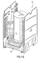
- Fig. 12 illustrates a three dimensional two plane battery assembly 82 for a spacecraft 84 designed for east and west battery implementation of the type disclosed in commonly assigned patent application Serial No. 07/985,452 filed by applicants herein on December 5, 1997 and entitled "Satellite With East and West Battery Radiators".
- This figure illustrates the compact nature of a large battery when packaged in three dimensions and requiring no resources from the prime north and south mounting and thermal radiator panels.
Landscapes
- Engineering & Computer Science (AREA)
- General Chemical & Material Sciences (AREA)
- Electrochemistry (AREA)
- Chemical Kinetics & Catalysis (AREA)
- Chemical & Material Sciences (AREA)
- Manufacturing & Machinery (AREA)
- Aviation & Aerospace Engineering (AREA)
- Remote Sensing (AREA)
- Health & Medical Sciences (AREA)
- Toxicology (AREA)
- General Health & Medical Sciences (AREA)
- Environmental Sciences (AREA)
- Environmental & Geological Engineering (AREA)
- Biodiversity & Conservation Biology (AREA)
- Life Sciences & Earth Sciences (AREA)
- Battery Mounting, Suspending (AREA)
- Secondary Cells (AREA)
- Photovoltaic Devices (AREA)
- Hybrid Cells (AREA)
Claims (6)
- Un système de batterie pour véhicules spatiaux comprenant:caractérisé en ce que chacune des pluralités d'éléments de batterie (34) est montée sur la surface de montage respective dudit panneau de montage plan et fait saillie en éloignement de cette surface.un panneau de montage plan (54) ayant des première et seconde surfaces de montage opposées;une pluralité d'éléments de batterie (34) en continuité électrique comprenant un premier ensemble de batterie (50) monté sur ladite première surface de montage dudit panneau de montage plan et répartis sur elle en un unique plan; etune pluralité d'éléments de batterie (34) en continuité électrique comprenant un second ensemble de batterie (52) monté sur ladite seconde surface de montage dudit panneau de montage plan et répartis sur elle en un unique plan, le plan dudit second ensemble de batterie étant espacé du plan dudit premier ensemble de batterie;
- Un système de batterie pour véhicules spatiaux selon la revendication 1, comprenant des moyens d'égalisation de la température (56) pour répartir uniformément dans toute la surface dudit panneau de montage plan (54) la chaleur émanant desdits éléments de batterie contenus dans chacun desdits premier et second ensembles de batterie.
- Un système de batterie pour véhicules spatiaux selon la revendication 2, dans lequel lesdits moyens d'égalisation de la température comprennent une pluralité de conduits d'évacuation de la chaleur (56) noyés dans ledit panneau de montage plan (54) et reliés thermiquement auxdits éléments de batterie.
- Un système de batterie pour véhicules spatiaux selon la revendication 1, comprenant:des moyens formant radiateur thermique (58) pour rayonner le chaleur dans l'espace lointain; etdes moyens conducteurs de la chaleur (56) reliant thermiquement ledit panneau de montage plan (54) auxdits moyens formant radiateur thermique (58) pour évacuer la chaleur dudit panneau de montage plan et la transférer auxdits moyens formant radiateur.
- Un système de batterie pour véhicules spatiaux comprenant:dans lequel les plaques de montage (54) des premier et second ensembles de batterie sont espacées l'une de l'autre en étant disposées dans des plans parallèles;un premier ensemble de batterie comportant des éléments de batterie (34) disposés dans deux plans, une plaque de montage commune (54) étant disposée entre eux;un second ensemble de batterie comportant des éléments de batterie (34) disposés dans deux plans, une plaque de montage commune (54) étant disposée entre eux;
caractérisé en ce que chacune des pluralités d'éléments de batterie (34) est montée sur la surface de montage respective dudit panneau de montage plan et fait saillie en éloignement de cette surface. - Un véhicule spatial comprenant un système de batterie pour véhicules spatiaux selon l'une quelconque des revendications précédentes.
Applications Claiming Priority (2)
| Application Number | Priority Date | Filing Date | Title |
|---|---|---|---|
| US97556 | 1998-06-15 | ||
| US09/097,556 US6207315B1 (en) | 1998-06-15 | 1998-06-15 | Three dimensional battery for space applications |
Publications (2)
| Publication Number | Publication Date |
|---|---|
| EP0966051A1 EP0966051A1 (fr) | 1999-12-22 |
| EP0966051B1 true EP0966051B1 (fr) | 2002-04-24 |
Family
ID=22264010
Family Applications (1)
| Application Number | Title | Priority Date | Filing Date |
|---|---|---|---|
| EP19990304639 Expired - Lifetime EP0966051B1 (fr) | 1998-06-15 | 1999-06-15 | Système de batteries pour véhicules spatiaux |
Country Status (4)
| Country | Link |
|---|---|
| US (1) | US6207315B1 (fr) |
| EP (1) | EP0966051B1 (fr) |
| JP (1) | JP2000036329A (fr) |
| DE (1) | DE69901325T2 (fr) |
Families Citing this family (5)
| Publication number | Priority date | Publication date | Assignee | Title |
|---|---|---|---|---|
| US7967256B2 (en) * | 2007-05-08 | 2011-06-28 | Lockheed Martin Corporation | Spacecraft battery thermal management system |
| US10457425B2 (en) * | 2012-10-18 | 2019-10-29 | The Boeing Company | Spacecraft with anti nadir battery radiator |
| EP3259189B1 (fr) * | 2015-06-02 | 2018-07-18 | Airbus Defence and Space SAS | Satellite artificiel |
| US9887401B2 (en) * | 2015-08-21 | 2018-02-06 | The Boeing Company | Battery assembly, battery containment apparatus, and related methods of manufacture |
| US10780998B1 (en) * | 2017-03-22 | 2020-09-22 | Space Systems/Loral, Llc | Spacecraft design with multiple thermal zones |
Family Cites Families (14)
| Publication number | Priority date | Publication date | Assignee | Title |
|---|---|---|---|---|
| US2014832A (en) * | 1934-01-16 | 1935-09-17 | Burgess Battery Co | Battery |
| US4828022A (en) | 1980-03-04 | 1989-05-09 | Ford Aerospace & Communications Corporation | Heat conducting sleeve |
| US4346151A (en) | 1980-12-29 | 1982-08-24 | The Gates Rubber Company | Multicell sealed rechargeable battery |
| US4420545A (en) | 1981-11-05 | 1983-12-13 | Ford Aerospace & Communications Corporation | Lightweight metal-gas battery |
| GB8715708D0 (en) | 1987-07-03 | 1987-08-12 | Chloride Silent Power Ltd | Batteries |
| DE3735931A1 (de) * | 1987-10-23 | 1989-05-03 | Asea Brown Boveri | Hochtemperaturspeicherbatterie |
| US4840855A (en) * | 1988-03-28 | 1989-06-20 | Michael Foti | Battery life extender |
| CA2038354A1 (fr) | 1990-03-30 | 1991-10-01 | William H. Kelly | Accumulateur ni-h2 a proprietes thermiques ameliorees |
| US5096788A (en) | 1990-10-05 | 1992-03-17 | Motorola, Inc. | Weldless battery pack |
| FR2676144B1 (fr) | 1991-05-03 | 1993-07-16 | Accumulateurs Fixes | Batterie d'accumulateurs nickel-hydrogene. |
| US5310141A (en) | 1992-09-21 | 1994-05-10 | General Electric Co. | Battery thermal control arrangement |
| FR2710899B1 (fr) * | 1993-10-08 | 1995-12-15 | Matra Marconi Space France | Satellite géostationnaire à accumulateurs d'énergie électrique. |
| US5510208A (en) * | 1994-09-28 | 1996-04-23 | Space Systems/Loral, Inc. | Composite battery cell sleeve |
| US5948556A (en) * | 1997-10-22 | 1999-09-07 | Space Systems/Loral, Inc. | Massively parallel spacecraft battery cell module design |
-
1998
- 1998-06-15 US US09/097,556 patent/US6207315B1/en not_active Expired - Fee Related
-
1999
- 1999-06-14 JP JP16710499A patent/JP2000036329A/ja active Pending
- 1999-06-15 DE DE69901325T patent/DE69901325T2/de not_active Expired - Fee Related
- 1999-06-15 EP EP19990304639 patent/EP0966051B1/fr not_active Expired - Lifetime
Also Published As
| Publication number | Publication date |
|---|---|
| JP2000036329A (ja) | 2000-02-02 |
| DE69901325D1 (de) | 2002-05-29 |
| DE69901325T2 (de) | 2002-12-12 |
| US6207315B1 (en) | 2001-03-27 |
| EP0966051A1 (fr) | 1999-12-22 |
Similar Documents
| Publication | Publication Date | Title |
|---|---|---|
| EP0780295B1 (fr) | Agencement de charge utile modulaire | |
| AU2020275316B2 (en) | Thermal management system for structures in space | |
| US7967256B2 (en) | Spacecraft battery thermal management system | |
| EP2673194B1 (fr) | Satellite à multiples rapports de forme | |
| US6776220B1 (en) | Spacecraft radiator system using crossing heat pipes | |
| US9889951B1 (en) | Spacecraft east-west radiator assembly | |
| US20110108080A1 (en) | Thermoelectric generator assembly and system | |
| JP4094930B2 (ja) | 人工衛星 | |
| EP0891926A1 (fr) | Système de contrÔle thermique pour vaisseau spatial | |
| JPH11240499A (ja) | 東西電池ラジエータを有する衛星 | |
| US8703319B1 (en) | Light-weight battery apparatus | |
| CN219017902U (zh) | 星载雷达天线及卫星 | |
| KR20060090674A (ko) | 평면 고체 산화물 연료전지용 유연성 적층체 | |
| EP0966051B1 (fr) | Système de batteries pour véhicules spatiaux | |
| JPH07237600A (ja) | 電気エネルギー用蓄電池を備えた地球軌道の人工衛星 | |
| CA2821532C (fr) | Astronef avec regulateur thermique de la pile anti nadir | |
| EP1041002A2 (fr) | Boíter protecteur pour l'équipement de véhicules aériens, spatiaux ou terrestres | |
| RU2268207C2 (ru) | Способ терморегулирования космического аппарата и устройство для его осуществления | |
| Lyman et al. | Application of Emerging Structural Energy Storage Technology to Small Satellite Systems | |
| WO2025183745A2 (fr) | Centres de données spatiaux | |
| Ehster | The Stentor Programme | |
| Curbelié et al. | STENTOR programme: An ongoing and efficient way for preparing the future | |
| Tatard | Li-ion battery for Geo satellites | |
| JOY et al. | Advanced thermal and power systems for the SATCOM-Ku satellites | |
| Gorland | Results from Symposium on Future Orbital power systems technology requirements |
Legal Events
| Date | Code | Title | Description |
|---|---|---|---|
| PUAI | Public reference made under article 153(3) epc to a published international application that has entered the european phase |
Free format text: ORIGINAL CODE: 0009012 |
|
| AK | Designated contracting states |
Kind code of ref document: A1 Designated state(s): DE FR GB IT |
|
| AX | Request for extension of the european patent |
Free format text: AL;LT;LV;MK;RO;SI |
|
| RIN1 | Information on inventor provided before grant (corrected) |
Inventor name: HALL, JOHN C. Inventor name: GELON, WALTER S. |
|
| 17P | Request for examination filed |
Effective date: 20000112 |
|
| AKX | Designation fees paid |
Free format text: DE FR GB IT |
|
| 17Q | First examination report despatched |
Effective date: 20010109 |
|
| GRAG | Despatch of communication of intention to grant |
Free format text: ORIGINAL CODE: EPIDOS AGRA |
|
| GRAG | Despatch of communication of intention to grant |
Free format text: ORIGINAL CODE: EPIDOS AGRA |
|
| GRAH | Despatch of communication of intention to grant a patent |
Free format text: ORIGINAL CODE: EPIDOS IGRA |
|
| REG | Reference to a national code |
Ref country code: GB Ref legal event code: IF02 |
|
| GRAH | Despatch of communication of intention to grant a patent |
Free format text: ORIGINAL CODE: EPIDOS IGRA |
|
| GRAA | (expected) grant |
Free format text: ORIGINAL CODE: 0009210 |
|
| AK | Designated contracting states |
Kind code of ref document: B1 Designated state(s): DE FR GB IT |
|
| REG | Reference to a national code |
Ref country code: GB Ref legal event code: FG4D |
|
| REF | Corresponds to: |
Ref document number: 69901325 Country of ref document: DE Date of ref document: 20020529 |
|
| PGFP | Annual fee paid to national office [announced via postgrant information from national office to epo] |
Ref country code: FR Payment date: 20020530 Year of fee payment: 4 |
|
| PGFP | Annual fee paid to national office [announced via postgrant information from national office to epo] |
Ref country code: DE Payment date: 20020620 Year of fee payment: 4 |
|
| ET | Fr: translation filed | ||
| PLBE | No opposition filed within time limit |
Free format text: ORIGINAL CODE: 0009261 |
|
| STAA | Information on the status of an ep patent application or granted ep patent |
Free format text: STATUS: NO OPPOSITION FILED WITHIN TIME LIMIT |
|
| 26N | No opposition filed |
Effective date: 20030127 |
|
| PG25 | Lapsed in a contracting state [announced via postgrant information from national office to epo] |
Ref country code: GB Free format text: LAPSE BECAUSE OF NON-PAYMENT OF DUE FEES Effective date: 20030615 |
|
| PG25 | Lapsed in a contracting state [announced via postgrant information from national office to epo] |
Ref country code: DE Free format text: LAPSE BECAUSE OF NON-PAYMENT OF DUE FEES Effective date: 20040101 |
|
| GBPC | Gb: european patent ceased through non-payment of renewal fee |
Effective date: 20030615 |
|
| PG25 | Lapsed in a contracting state [announced via postgrant information from national office to epo] |
Ref country code: FR Free format text: LAPSE BECAUSE OF NON-PAYMENT OF DUE FEES Effective date: 20040227 |
|
| REG | Reference to a national code |
Ref country code: FR Ref legal event code: ST |
|
| PG25 | Lapsed in a contracting state [announced via postgrant information from national office to epo] |
Ref country code: IT Free format text: LAPSE BECAUSE OF NON-PAYMENT OF DUE FEES;WARNING: LAPSES OF ITALIAN PATENTS WITH EFFECTIVE DATE BEFORE 2007 MAY HAVE OCCURRED AT ANY TIME BEFORE 2007. THE CORRECT EFFECTIVE DATE MAY BE DIFFERENT FROM THE ONE RECORDED. Effective date: 20050615 |