EP0966058A1 - Atténuateur variable pour guide d' ondes rectangulaire - Google Patents
Atténuateur variable pour guide d' ondes rectangulaire Download PDFInfo
- Publication number
- EP0966058A1 EP0966058A1 EP99303453A EP99303453A EP0966058A1 EP 0966058 A1 EP0966058 A1 EP 0966058A1 EP 99303453 A EP99303453 A EP 99303453A EP 99303453 A EP99303453 A EP 99303453A EP 0966058 A1 EP0966058 A1 EP 0966058A1
- Authority
- EP
- European Patent Office
- Prior art keywords
- plunger element
- waveguide
- shaft
- elbow
- plunger
- Prior art date
- Legal status (The legal status is an assumption and is not a legal conclusion. Google has not performed a legal analysis and makes no representation as to the accuracy of the status listed.)
- Withdrawn
Links
- 230000001419 dependent effect Effects 0.000 claims description 3
- 230000000295 complement effect Effects 0.000 claims description 2
- 230000005684 electric field Effects 0.000 description 3
- 238000010521 absorption reaction Methods 0.000 description 2
- 230000000694 effects Effects 0.000 description 2
- 238000003754 machining Methods 0.000 description 2
- 230000000644 propagated effect Effects 0.000 description 2
- XAGFODPZIPBFFR-UHFFFAOYSA-N aluminium Chemical compound [Al] XAGFODPZIPBFFR-UHFFFAOYSA-N 0.000 description 1
- 229910052782 aluminium Inorganic materials 0.000 description 1
- 238000013459 approach Methods 0.000 description 1
- 230000002238 attenuated effect Effects 0.000 description 1
- 239000004020 conductor Substances 0.000 description 1
- 238000003780 insertion Methods 0.000 description 1
- 230000037431 insertion Effects 0.000 description 1
- 239000000463 material Substances 0.000 description 1
Images



Classifications
-
- H—ELECTRICITY
- H01—ELECTRIC ELEMENTS
- H01P—WAVEGUIDES; RESONATORS, LINES, OR OTHER DEVICES OF THE WAVEGUIDE TYPE
- H01P1/00—Auxiliary devices
- H01P1/22—Attenuating devices
- H01P1/222—Waveguide attenuators
Definitions
- the present invention relates to an attenuation device for rectangular waveguides. It can be applied especially in the field of microwave equipment.
- Attenuation devices for the attenuation, on a waveguide portion, of the electrical power transmitted in order to regulate the level of power received by a circuit that is positioned downline to the waveguide in the direction of propagation of the waves.
- attenuators especially attenuators based on PIN diodes and plate attenuators.
- the present invention relates especially to plate attenuators.
- a plate is introduced into the waveguide by a longitudinal slot parallel to the axis of propagation of the microwaves.
- the plate is made of a resistive material that absorbs the electrical energy propagated in the waveguide.
- the incident energy that gets propagated in the guide is attenuated when it passes into the guide portion crossed by the plate.
- the amplitude of the attenuation is a function of the plate portion inserted into the waveguide, which is given the task of acting as an obstacle to the propagation of the wave in the guide.
- the amplitude of the attenuation is also a function of the position of the plate with respect to the plane of symmetry of the guide parallel to the electrical field (the plane where the amplitude of the electrical field is the maximum).
- the attenuation is the maximum when the plate is introduced into this plane, namely the center of the waveguide.
- the device has a plunger disk with a substantially plane shape designed to be inserted into a waveguide through a longitudinal slot along the axis of propagation of the waves. This slot is made in the upper face of the guide, preferably in its middle.
- the plunger disk is mounted on a driving shaft whose axis is orthogonal to the axis of propagation of the waves. It is thus in a plane parallel to the electrical field of the electromagnetic waves.
- the shaft on which the disk is mounted is connected to an adjustable dial plate.
- the contour of the disk is not circular with respect to the center of the rotation shaft so that the rotation of the disk causes a variation in the surface of the disk inserted into the waveguide.
- a rotation of the dial plate drives a rotation of the disk which may be thus set at different angular positions corresponding to various amplitudes of attenuation.
- the aim of the invention is to resolve the problems of miniaturization encountered with existing devices. Indeed, to obtain attenuation values of several tens of decibels, the disk portion inserted into the waveguide must be relatively large. To this end, the existing devices are provided with a plunging disk having a large radius to increase the disk portion submerged in the guide.
- the present invention seeks to mitigate this major drawback of the prior art by proposing a relatively compact attenuation device with a simple design.
- an object of the invention is a variable attenuation device for a rectangular waveguide, of the type comprising a substantially plane plunger element with a rounded shape designed to be introduced perpendicularly into said waveguide through a longitudinal slot made along the axis of propagation of the waves in a first face of said guide, the plunger element being rotationally mobile about an off-centered axis so that the portion of the plunger element introduced into the waveguide is a function of the angular position of said plunger element, wherein said plunger element and said longitudinal slot are positioned at the level of an elbow formed by said waveguide.
- the result thereof is an increase in the proportion of plunger element introduced into the guide in relation to a rectilinear waveguide.
- the attenuation sought may then be obtained with a small-sized device.
- the shape of the contour of the plunger element and the position of its axis are designed so that the attenuation is linearly dependent on the angular position of the plunger element.
- the contour of the plunger element and the position of its rotational axis are then defined so that, in a first extreme angular position, the contour of the plunger element is tangential to the first face of the elbow in such a way that the portion of the plunger element introduced into the waveguide is zero and, in a second extreme angular position, the plunger element completely goes through the waveguide at the level of the elbow so that the portion of the plunger element introduced into the waveguide is the maximum.
- a scalloping is made, at the level of the elbow, in the face opposite the first face of the waveguide so that the plunger element can completely cross the waveguide.
- variable attenuation device comprises a body formed by two symmetrical parts each comprising a groove and a blind hollow leading into the interior of said groove so that, once the two parts are assembled, the grooves form said waveguide and the blind hollows form a cavity designed to receive the plunger element, which is introduced into said waveguide at the intersection between said grooves and said blind hollows corresponding to said longitudinal slot.
- the contour of the plunger element comprises:
- the rotational axis of the plunger element may be positioned so that the distance between the first rectilinear part and the plunger element is greater than the distance between this first rectilinear part and the second rectilinear part.
- variable attenuator is also distinguished by its system for the driving of the plunger element.
- the plunger element is mounted on a rotational driving shaft which has an end gear wheel to be coupled externally to a motor borne on an L-shaped support fixed by its base to the body.
- This plunger shaft is engaged in a neck collar going through the body and the base of said motor support by means of through bores adjusted to its external diameter, the collar comprising an internal end shoulder designed to take support on the edge of said bore and being furthermore interposed on the shaft between an internal shoulder of this shaft and said drive gear wheel, the gear wheel being engaged in the external end of the shaft and being adjusted and held axially on it by means of a screw entering the end of the shaft.
- Figure 1 shows an exploded view of an attenuation device according to the invention.
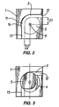
- This device consists of a body formed by two symmetrical parts 1 and 2. These parts 1 and 2 each have a groove 3 (not shown in Figure 2) with a depth equal to a and a width equal to b and a blind hollow 4 (not shown in the part 2) with a depth equal to c opening into the interior of the groove.
- the two facing grooves form a waveguide with a width 2* a and a height b and the two blind hollows form a cavity enclosing a plunger element 5 that is rotationally mobile around an off-centered axis 6 orthogonal to said parts 1 and 2.
- parts 1 and 2 are made by machining a block of conductive material such as aluminum.
- the intersection between the grooves 3 and the blind hollows 4 forms a longitudinal slot 7 through which the plunger element 5 is introduced into the waveguide.
- the cavity is circular and its center coincides with the rotational axis 6 of the plunger element 5.
- Holes 8 and 9 are made in the parts 1 and 2 respectively to receive a rotational shaft 10 of the plunger element 5.
- the radius of the cavity is chosen to be greater than the greatest distance between the rotational axis 6 and the contour of the plunger element 5, and the thickness of the plunger element is smaller than 2* c .
- said grooves 3 comprise at least one curved section so that the waveguide constituted by the two grooves form an elbow and the plunger element 5 is inserted into the waveguide at this elbow.
- the longitudinal slot 7 is at this elbow.
- the insertion of the plunger element into this curved section of the guide enables an increase in the portion of the plunger element submerged in the guide without any need to increase the size of this element. For one and the same value of attenuation, it is thus possible to very substantially reduce the size of the plunger element with respect to a rectilinear waveguide.
- the elbow shown in Figures 1 to 9 of the present application is a 90° elbow. It is possible to consider the use of elbows creating a different change in direction. The utility of the gain in size of the attenuator would then vary depending on the value of the angle of this elbow.
- the attenuation is chosen so as to be linearly dependent on the angular position of the plunger element.
- This dependence is related to the shape of the contour of the plunger element 5 and the position of its rotational axis 6 with respect to the groove 3.
- D1 is the reference given to the distance between the rotational axis 6 and the inner face of the rectilinear section 12 of the guide
- D2 is the reference given to the distance between the rotational axis 6 and the inner face of the rectilinear section 13 of the guide
- D1>D2 will be chosen to obtain a linear dependence, given that the plunger element 5 rotates in the anticlockwise direction.
- This off-centered position of the axis 6 with respect to the rectilinear sections 12 and 13 of the guide will enable the plunger element to be introduced more deeply into the waveguide for the low angular values of the plunger element.
- a scalloping 14 is made in the external face of the waveguide, at the curved section 11 and the rectilinear section 13, so that the plunger element can completely go through the waveguide and pivot without being encumbered about its axis of rotation.
- the scalloping 14 has the shape of an arc of a circle having the same radius and the same center as the cavity formed by the two blind hollows 4.
- the scalloping 14 is made at the same time as the blind hollow 4 in one and the same machining operation.
- the linearization of the attenuation curve can be made more precise by acting on the shape of the contour of the plunger element.
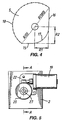
- a preferred embodiment of the plunger element is shown in Figure 4. This contour shape has been determined empirically.
- the contour of the plunger element 5 has two orthogonal rectilinear portions 15 and 16 whose neighboring ends meet by an elbow 17 matched with the elbow of the waveguide.
- the remaining part of the contour between the distant ends of the portions 15 and 16 is an essentially convex, curved segment 18.
- the center of rotation of the plunger element 5 is not equidistant from the two rectilinear portions 15 and 16. In the embodiment shown it is closer to the portion 16.
- R1 refers to the distance between the rectilinear portion 15 and the center of rotation 6
- R2 refers to the distance between the rectilinear portion 16 and the center of rotation.
- R1 13.2 mm
- R2 16.7 mm
- the curved segment 18 is defined by a sequence of values R( ⁇ ) each representing the distance between a point of the curved segment 18 and the center of rotation, where ⁇ designates the angle between the distal end of the rectilinear portion 15 and the point of the curved segment considered and varies between 0° and 180°.
- the values R(0°) and R(180°) correspond respectively to the distance between the distal ends of the rectilinear portions 15 and 16 and the center of rotation of the plunger element.
- the set of values R( ⁇ ) pertaining to the prototype are contained in the appended table. These values are indicated every 9°.
- variable attenuator according to the invention is also distinguished by the rotational driving system of its plunger element which has been designed especially with a view to optimum reliability of operation, taking into account all conditions of use. These conditions of use are often severe, especially as regards the variations of temperature which may go up to more than 100°C and give rise to a major risk of mechanical jamming.
- the plunger element 5 is fixedly joined to a shaft 21 going through the body part 2 by a through bore 24 to be driven externally by a motor 19.
- the plunger shaft 21 is provided at one end with a gear wheel 20 driven by the output shaft of the motor 19.
- the gear wheel 20 has a concave rim designed to partially envelope the shaft of the motor 19 on a portion of this motor forming an endless screw, engaged with a complementary set of teeth of said concave rim.
- the motor 19 is mounted on the wing of an L-shaped support 22 whose base is applied and fixed to the external wall of the body part 2, the output shaft of the motor 19 going through said wing. Furthermore, the plunger shaft 21 is mounted without clearance in a neck collar 23 that is shouldered so as to take support at its internal end on the edge of the through bore 24, cross said body part 2 by this bore and then cross the base of the L-shaped support through a bore 25, the two bores 24 and 25 being adjusted to its external diameter.
- the bores 24 and 25 are shown in Figure 9.
- the neck collar 23 is interposed between an internal shoulder of this collar 26 and the gear wheel 20 which is engaged on the external end of the shaft and adjusted and kept in position by means of an end screw 27.
- the collar 23 also determines the positioning of the plunger 5 in the direction of this rotational axis. Indeed, as can be seen clearly in Figure 8, the plunger element 5, engaged on its drive shaft 21, is held against a shoulder 28 of this shaft and the internal end of the collar 23. Hence, it is held at a distance from the bottom of the blind hollow 4 in the body part 2 that corresponds to the axial distance between the internal end of the collar 23 and its shoulder 28.
- Figure 10 shows some values of the attenuation generated by an attenuation device corresponding to the preferred embodiment of the invention as a function of the angular position of its plunger element.
- the plunger element used is the one shown in Figure 4 with a thickness of 2 mm.
- the attenuation values are given for an incident signal with a frequency of 13 GHz.
- the attenuation is shown for the values of angular position ranging from 0°, corresponding to the case where the contour of the plunger element is tangential to the internal face of the waveguide, to 235° corresponding to a pivoting of the plunger element by 235° in the anticlockwise direction (the position for which the attenuation is the maximum).
- This attenuation curve shows that the attenuation of the incident wave does not result solely from the absorption of its energy by the plunger element 5. Otherwise, the maximum value of the attenuation would be located around the position 180° (it would not be exactly at 180° owing to the non-uniformity of the curved portion 18 of the plunger element 5). It would appear that phenomena of reflection of the incident wave explain this shift in the angular position of the maximum.
Landscapes
- Non-Reversible Transmitting Devices (AREA)
Priority Applications (1)
| Application Number | Priority Date | Filing Date | Title |
|---|---|---|---|
| EP99303453A EP0966058A1 (fr) | 1998-06-15 | 1999-05-04 | Atténuateur variable pour guide d' ondes rectangulaire |
Applications Claiming Priority (3)
| Application Number | Priority Date | Filing Date | Title |
|---|---|---|---|
| EP98460022 | 1998-06-15 | ||
| EP98460022A EP0966057A1 (fr) | 1998-06-15 | 1998-06-15 | Atténuateur variable pour guide d'ondes rectangulaire |
| EP99303453A EP0966058A1 (fr) | 1998-06-15 | 1999-05-04 | Atténuateur variable pour guide d' ondes rectangulaire |
Publications (1)
| Publication Number | Publication Date |
|---|---|
| EP0966058A1 true EP0966058A1 (fr) | 1999-12-22 |
Family
ID=26151803
Family Applications (1)
| Application Number | Title | Priority Date | Filing Date |
|---|---|---|---|
| EP99303453A Withdrawn EP0966058A1 (fr) | 1998-06-15 | 1999-05-04 | Atténuateur variable pour guide d' ondes rectangulaire |
Country Status (1)
| Country | Link |
|---|---|
| EP (1) | EP0966058A1 (fr) |
Citations (7)
| Publication number | Priority date | Publication date | Assignee | Title |
|---|---|---|---|---|
| US2491644A (en) * | 1945-08-24 | 1949-12-20 | Bell Telephone Labor Inc | Attenuator |
| GB640057A (en) * | 1947-12-30 | 1950-07-12 | Waldemar Rosenberg | Improvements in or relating to electromagnetic wave guides |
| US2613270A (en) * | 1946-05-24 | 1952-10-07 | Aircraft Radio Corp | Wave guide attenuator |
| US2619538A (en) * | 1944-05-23 | 1952-11-25 | Westinghouse Electric Corp | Wave guide attenuator |
| DE1910362A1 (de) * | 1969-02-28 | 1970-09-17 | Licentia Gmbh | Anordnung zum Erzeugen einer einstellbaren Einfuegdaempfung |
| JPS57194604A (en) * | 1981-05-27 | 1982-11-30 | Nec Corp | Waveguide variable attenuator |
| DE3608451A1 (de) * | 1986-03-14 | 1987-09-17 | Licentia Gmbh | Daempfungsglied fuer hohlleiter |
-
1999
- 1999-05-04 EP EP99303453A patent/EP0966058A1/fr not_active Withdrawn
Patent Citations (7)
| Publication number | Priority date | Publication date | Assignee | Title |
|---|---|---|---|---|
| US2619538A (en) * | 1944-05-23 | 1952-11-25 | Westinghouse Electric Corp | Wave guide attenuator |
| US2491644A (en) * | 1945-08-24 | 1949-12-20 | Bell Telephone Labor Inc | Attenuator |
| US2613270A (en) * | 1946-05-24 | 1952-10-07 | Aircraft Radio Corp | Wave guide attenuator |
| GB640057A (en) * | 1947-12-30 | 1950-07-12 | Waldemar Rosenberg | Improvements in or relating to electromagnetic wave guides |
| DE1910362A1 (de) * | 1969-02-28 | 1970-09-17 | Licentia Gmbh | Anordnung zum Erzeugen einer einstellbaren Einfuegdaempfung |
| JPS57194604A (en) * | 1981-05-27 | 1982-11-30 | Nec Corp | Waveguide variable attenuator |
| DE3608451A1 (de) * | 1986-03-14 | 1987-09-17 | Licentia Gmbh | Daempfungsglied fuer hohlleiter |
Non-Patent Citations (1)
| Title |
|---|
| PATENT ABSTRACTS OF JAPAN vol. 7, no. 45 (E - 160)<1190> 23 February 1983 (1983-02-23) * |
Similar Documents
| Publication | Publication Date | Title |
|---|---|---|
| US2607849A (en) | Control of polarization in wave guides and wave guide systems | |
| US4808950A (en) | Electromagnetic dispersive delay line | |
| US5801598A (en) | High-power RF load | |
| CA2284372C (fr) | Transducteur orthomodal a couplage avec doubles parois laterales a desaxage septa orthogonal a partir de l'axe du transducteur | |
| JP3279242B2 (ja) | 異種非放射性誘電体線路変換部構造およびその装置 | |
| EP0966058A1 (fr) | Atténuateur variable pour guide d' ondes rectangulaire | |
| US4271411A (en) | Detector for doppler device | |
| US4675633A (en) | Waveguide expansion joint | |
| Taub et al. | Submillimeter components using oversize quasi-optical waveguide | |
| CA2206549A1 (fr) | Structure d'alimentation d'antenne micro-ondes | |
| US5034711A (en) | Dielectric resonator support system for a waveguide | |
| US4358746A (en) | Rotary coupling joint | |
| EP1309030A1 (fr) | Elément coudé en guide d'ondes et dispositif de transmission comportant ledit élément | |
| JP3525884B2 (ja) | レンズアンテナ装置を有する無線装置 | |
| JPH06112708A (ja) | 導波管・平面線路変換器 | |
| EP0992076B1 (fr) | Attenuateur variable pour guide d'ondes rectangulaire | |
| Ishikawa et al. | 60 GHz band FM-pulse automotive radar front end using new type NRD guide and dielectric lens antenna | |
| JP3193757B2 (ja) | 導波管用無反射終端器 | |
| JP2000040902A (ja) | 長方形導波路用可変減衰器 | |
| EP0809318B1 (fr) | Circulateur | |
| RU2109375C1 (ru) | Антенно-фидерное устройство с вращающимся соединением и одновременным механическим сканированием диаграммы направленности | |
| US20240030576A1 (en) | Waveguide device for absorbing electromagnetic wave energy and method for assembling same | |
| JPH104303A (ja) | 導波管回路 | |
| JPH06140811A (ja) | 導波管型可変減衰器 | |
| KR100269587B1 (ko) | 마이크로웨이브 서큘레이터 |
Legal Events
| Date | Code | Title | Description |
|---|---|---|---|
| PUAI | Public reference made under article 153(3) epc to a published international application that has entered the european phase |
Free format text: ORIGINAL CODE: 0009012 |
|
| AK | Designated contracting states |
Kind code of ref document: A1 Designated state(s): DE FI FR GB SE |
|
| AX | Request for extension of the european patent |
Free format text: AL;LT;LV;MK;RO;SI |
|
| 17P | Request for examination filed |
Effective date: 20000608 |
|
| AKX | Designation fees paid |
Free format text: DE FI FR GB SE |
|
| STAA | Information on the status of an ep patent application or granted ep patent |
Free format text: STATUS: THE APPLICATION HAS BEEN WITHDRAWN |
|
| 18W | Application withdrawn |
Effective date: 20030213 |