EP0966099A1 - Leistungsverstärker mit Transform-Kombinierungsnetzwerken - Google Patents
Leistungsverstärker mit Transform-Kombinierungsnetzwerken Download PDFInfo
- Publication number
- EP0966099A1 EP0966099A1 EP99401335A EP99401335A EP0966099A1 EP 0966099 A1 EP0966099 A1 EP 0966099A1 EP 99401335 A EP99401335 A EP 99401335A EP 99401335 A EP99401335 A EP 99401335A EP 0966099 A1 EP0966099 A1 EP 0966099A1
- Authority
- EP
- European Patent Office
- Prior art keywords
- transform matrix
- order
- signals
- matrix circuit
- input
- Prior art date
- Legal status (The legal status is an assumption and is not a legal conclusion. Google has not performed a legal analysis and makes no representation as to the accuracy of the status listed.)
- Withdrawn
Links
- 239000011159 matrix material Substances 0.000 claims abstract description 50
- 230000010267 cellular communication Effects 0.000 claims abstract description 4
- 230000001413 cellular effect Effects 0.000 description 23
- 230000003321 amplification Effects 0.000 description 6
- 238000003199 nucleic acid amplification method Methods 0.000 description 6
- 238000013507 mapping Methods 0.000 description 5
- 238000000034 method Methods 0.000 description 4
- 238000004088 simulation Methods 0.000 description 4
- 230000000694 effects Effects 0.000 description 3
- 230000010363 phase shift Effects 0.000 description 3
- 238000010276 construction Methods 0.000 description 2
- 238000010586 diagram Methods 0.000 description 2
- 238000000342 Monte Carlo simulation Methods 0.000 description 1
- 238000004891 communication Methods 0.000 description 1
- 238000005516 engineering process Methods 0.000 description 1
- 238000005259 measurement Methods 0.000 description 1
Images


Classifications
-
- H—ELECTRICITY
- H03—ELECTRONIC CIRCUITRY
- H03F—AMPLIFIERS
- H03F3/00—Amplifiers with only discharge tubes or only semiconductor devices as amplifying elements
- H03F3/60—Amplifiers in which coupling networks have distributed constants, e.g. with waveguide resonators
- H03F3/602—Combinations of several amplifiers
-
- H—ELECTRICITY
- H04—ELECTRIC COMMUNICATION TECHNIQUE
- H04B—TRANSMISSION
- H04B7/00—Radio transmission systems, i.e. using radiation field
-
- H—ELECTRICITY
- H04—ELECTRIC COMMUNICATION TECHNIQUE
- H04L—TRANSMISSION OF DIGITAL INFORMATION, e.g. TELEGRAPHIC COMMUNICATION
- H04L25/00—Baseband systems
- H04L25/02—Details ; arrangements for supplying electrical power along data transmission lines
- H04L25/03—Shaping networks in transmitter or receiver, e.g. adaptive shaping networks
- H04L25/03006—Arrangements for removing intersymbol interference
- H04L2025/03433—Arrangements for removing intersymbol interference characterised by equaliser structure
- H04L2025/03439—Fixed structures
- H04L2025/03522—Frequency domain
Definitions
- the present invention relates generally to a power sharing amplifier system; and more particularly, related to a power sharing amplifier system for a cellular communication system.
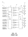
- FIG. 1A shows an 8 by 8 cellular transmitter configuration generally indicated as 100 similar to that shown and described in United States patent application serial no. 08/683,735.
- the 8 by 8 cellular configuration 100 includes eight separate low power transmitters generally indicated 102, an 8th order transform matrix circuit 104, eight amplifiers generally indicated 106, an 8 by 8 inverse transform matrix circuit 108, and eight antennas generally indicated as 110.
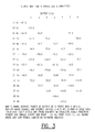
- Figure 1B shows a mapping of each input port to a respective output port in the 8th order cellular configuration.
- Figure 1C shows a chart of phase shifts for the 8th order transform matrix circuit 104 and the 8th order inverse transform matrix circuit 108 in the 8 by 8 cellular configuration.
- the amplification sharing technique used in the 8 by 8 cellular configuration 100 offers some advantages over the amplification technique of the standard cellular configuration.
- the amplifiers 108 effectively share the amplification of all the input signals, which provide inherent redundancy in the overall amplification of the input signals.
- the 8 by 8 cellular configurations 100 may be operating in a less desirable operating mode, but nevertheless it still operates and allows additional time for the failed amplifier to be repaired or replaced.
- the 8 by 8 cellular configuration 100 also uses fewer amplifiers than the standard cellular configuration if redundant amplifiers are maintained for each sector.
- one disadvantage of the 8 by 8 cellular configuration 100 shown is that the amplification sharing technique results in intermodulation products between the eight input signals to the various amplifiers that distort the amplified RF output signal sent to and transmitted by the antenna 110.
- the present invention provides a power sharing amplifier system for a cellular communications system, having with an 8th order transform matrix circuit, eight power sharing amplifiers and an 8th order inverse transform matrix circuit.
- the 8th order transform matrix circuit has six input ports that respond to six RF input signals and has eight output ports that provide 8th order transform matrix RF input signals.
- the 8th order transform matrix circuit also has two input ports that do not receive input signals, but instead are coupled through a resistor to ground.
- the eight power sharing amplifiers respond to the 8th order transform matrix input signals and provide eight amplified transformed RF signals.
- the 8th order inverse transform matrix circuit has eight input ports that responds to the eight amplified transformed signals, and has six output ports that provide six inverse transform amplified RF output signals to six output ports.
- the 8th order inverse transform matrix circuit also has two output ports that do not provide output signals to an antenna, but instead are coupled through a resistor to ground for dissipating intermodulation distortion products.
- the present invention provides a new and unique power sharing amplifier system that reduces the undesirable effects of the intermodulation distortion products that result from the shared amplification technique.
- the invention comprises the features of construction, combination of elements, and arrangement of parts which will be exemplified in the construction hereinafter set forth, and the scope of the invention will be indicated in the claims.
- Figure 1A is block diagrams of a 8 by 8 cellular configurations similar to that shown and described in United States patent application serial no. 08/683,735.
- Figure 1B is a mapping of each input port to a respective output port for the 8 by 8 cellular configuration shown in Figure 1A.
- Figure 1C is a chart of phase shifts from input ports 1-8 to output ports A-H for an 8th order transform matrix or for an 8th order inverse transform matrix for the 8 by 8 cellular configuration shown in Figure 1A.
- Figure 2 is a block diagram of a 6 by 8 cellular configuration that is the subject matter of the present invention.
- Figure 3 is an output map for the 6 by 8 cellular configuration shown in Figure 2.
- Figure 2 shows a 6 by 8 cellular configuration generally indicated as 200 having a power sharing amplifying system 201 coupled between six low power transmitters, 202, 204, 206, 208, 210, 212 and six antennas 214, 216, 218, 220, 222, 224.
- a power sharing amplifying system 201 coupled between six low power transmitters, 202, 204, 206, 208, 210, 212 and six antennas 214, 216, 218, 220, 222, 224.
- the power sharing amplifying system 201 has an 8th order transform matrix circuit 230, eight amplifiers 232, 234, 236, 238, 240, 242, 244, 246, and an 8th order inverse transform matrix circuit 248.
- the 8th order transform matrix circuit 230 includes six input port nos. 1-8 labelled 250, 252, 254, 256, 258, 260 that respectively respond to six RF input signals from the six low power transmitters 202, 204, 206, 208, 210, 212. As shown, in the 6 by 8 cellular configuration 200, the 8th order transform matrix circuit 230 features two input ports 262, 264 that do not receive RF input signals but instead are each coupled to ground via respective resistors Ri1, Ri2.
- the 8th order transform matrix circuit 230 includes eight outputs ports A, B, C, D, E, F, G, H, for providing 8th order transform matrix RF input signals to the eight amplifiers 232, 234, 236, 238, 240, 242, 244, 246.
- the 8 by 8 transform matrix circuit 230 is an 8th order Fourier transform matrix with phase shifts shown in Figure 1C and input/output mapping shown in Figure 1B.
- the eight amplifiers 232, 234, 236, 238, 240, 242, 244, 246 are shared linear power amplifiers that respectively respond to the 8th order transform matrix RF input signals, and provide eight shared linear power amplified transform matrix RF input signals.
- the 8th order inverse transform matrix circuit 248 responds to the eight shared linear power amplified transform matrix RF input signals, for providing six inverse transform matrix amplified RF output signals from six output port nos. 1, 2 and 5-8, labelled 270, 272, 278, 280, 282, 284.
- the 8th order inverse transform matrix circuit 248 includes two output ports nos. 3 and 4, labelled 274, 276, that do not provide inverse transform matrix amplified RF output signals, but instead are each coupled to ground via respective resistors Rol, Ro2 to dissipate the intermodulation products.
- the 8th order inverse transform matrix circuit 248 is an 8th order Fourier inverse transform matrix.
- the power sharing amplifying system 201 can be used to improve system operation by sharing the amplifier power, regardless of the distribution of beam loading, as well as providing the improved reliability associated with any amplifier combining system.
- intermodulation products that occur when six signals are applied to any of the amplifiers take a variety of forms (see R. S. Larkin, "Multiple-Signal Intermodulation and Stability Considerations” IEEE Vehicular Technology Conference, 1991).
- the dominant intermodulation products are "third order" meaning that they are produced by a cubic nonlinearity in the amplifier. Restricting our consideration to narrow band systems (less than an octave of bandwidth) such as occurs for cellular telephone systems, there is a third-order product for each pair of input signals of the form 2f a - f b , where f a and f b are the frequencies of the two signals.
Landscapes
- Engineering & Computer Science (AREA)
- Computer Networks & Wireless Communication (AREA)
- Signal Processing (AREA)
- Power Engineering (AREA)
- Amplifiers (AREA)
- Transmitters (AREA)
Applications Claiming Priority (4)
| Application Number | Priority Date | Filing Date | Title |
|---|---|---|---|
| US09/098,896 US6381212B1 (en) | 1998-06-17 | 1998-06-17 | Power sharing amplifier system for amplifying multiple input signals with shared power amplifiers |
| US98660 | 1998-06-17 | ||
| US98896 | 1998-06-17 | ||
| US09/098,660 US6185182B1 (en) | 1996-07-26 | 1998-06-17 | Power sharing amplifier system for a cellular communications system |
Publications (1)
| Publication Number | Publication Date |
|---|---|
| EP0966099A1 true EP0966099A1 (de) | 1999-12-22 |
Family
ID=26794962
Family Applications (1)
| Application Number | Title | Priority Date | Filing Date |
|---|---|---|---|
| EP99401335A Withdrawn EP0966099A1 (de) | 1998-06-17 | 1999-06-03 | Leistungsverstärker mit Transform-Kombinierungsnetzwerken |
Country Status (3)
| Country | Link |
|---|---|
| EP (1) | EP0966099A1 (de) |
| KR (1) | KR100463611B1 (de) |
| IL (1) | IL129417A0 (de) |
Cited By (2)
| Publication number | Priority date | Publication date | Assignee | Title |
|---|---|---|---|---|
| WO2003081864A3 (en) * | 2002-03-19 | 2004-04-01 | Motorola Inc | Method and apparatus for reducing transmitter peak power requirements using dual matrices |
| WO2003081863A3 (en) * | 2002-03-19 | 2004-07-22 | Motorola Inc | Apparatus for improving transmitter redundancy, and method |
Citations (5)
| Publication number | Priority date | Publication date | Assignee | Title |
|---|---|---|---|---|
| EP0704964A2 (de) * | 1994-09-29 | 1996-04-03 | Radio Frequency Systems Inc. | Leistungsaufteilungssystem für HF-Hochleistungsverstärker |
| US5604462A (en) * | 1995-11-17 | 1997-02-18 | Lucent Technologies Inc. | Intermodulation distortion detection in a power shared amplifier network |
| US5638024A (en) * | 1994-01-11 | 1997-06-10 | Ericsson Inc. | Waste energy control and management in power amplifiers |
| WO1998010513A1 (en) * | 1996-09-04 | 1998-03-12 | Motorola Inc. | Method and system for preventing an amplifier overload condition in a hybrid matrix amplifier array |
| US5764104A (en) * | 1996-05-31 | 1998-06-09 | Motorola, Inc. | Method and system for reducing noise in a hybrid matrix amplifier |
Family Cites Families (4)
| Publication number | Priority date | Publication date | Assignee | Title |
|---|---|---|---|---|
| US5163181A (en) * | 1988-10-21 | 1992-11-10 | Harris Corporation | Multiple rf signal amplification method and apparatus |
| US5646631A (en) * | 1995-12-15 | 1997-07-08 | Lucent Technologies Inc. | Peak power reduction in power sharing amplifier networks |
| US5805575A (en) * | 1996-08-19 | 1998-09-08 | Motorola, Inc. | Apparatus and method for providing a beacon signal in a wireless communication system |
| US5825762A (en) * | 1996-09-24 | 1998-10-20 | Motorola, Inc. | Apparatus and methods for providing wireless communication to a sectorized coverage area |
-
1999
- 1999-04-13 IL IL12941799A patent/IL129417A0/xx unknown
- 1999-06-03 EP EP99401335A patent/EP0966099A1/de not_active Withdrawn
- 1999-06-16 KR KR10-1999-0022458A patent/KR100463611B1/ko not_active Expired - Fee Related
Patent Citations (5)
| Publication number | Priority date | Publication date | Assignee | Title |
|---|---|---|---|---|
| US5638024A (en) * | 1994-01-11 | 1997-06-10 | Ericsson Inc. | Waste energy control and management in power amplifiers |
| EP0704964A2 (de) * | 1994-09-29 | 1996-04-03 | Radio Frequency Systems Inc. | Leistungsaufteilungssystem für HF-Hochleistungsverstärker |
| US5604462A (en) * | 1995-11-17 | 1997-02-18 | Lucent Technologies Inc. | Intermodulation distortion detection in a power shared amplifier network |
| US5764104A (en) * | 1996-05-31 | 1998-06-09 | Motorola, Inc. | Method and system for reducing noise in a hybrid matrix amplifier |
| WO1998010513A1 (en) * | 1996-09-04 | 1998-03-12 | Motorola Inc. | Method and system for preventing an amplifier overload condition in a hybrid matrix amplifier array |
Cited By (4)
| Publication number | Priority date | Publication date | Assignee | Title |
|---|---|---|---|---|
| WO2003081864A3 (en) * | 2002-03-19 | 2004-04-01 | Motorola Inc | Method and apparatus for reducing transmitter peak power requirements using dual matrices |
| WO2003081863A3 (en) * | 2002-03-19 | 2004-07-22 | Motorola Inc | Apparatus for improving transmitter redundancy, and method |
| US7012970B2 (en) | 2002-03-19 | 2006-03-14 | Motorola, Inc. | Method and apparatus for reducing transmitter peak power requirements |
| US7020215B2 (en) | 2002-03-19 | 2006-03-28 | Motorola, Inc. | Method and apparatus for reducing transmitter peak power requirements using dual matrices |
Also Published As
| Publication number | Publication date |
|---|---|
| KR20000006204A (ko) | 2000-01-25 |
| IL129417A0 (en) | 2000-02-17 |
| KR100463611B1 (ko) | 2004-12-29 |
Similar Documents
| Publication | Publication Date | Title |
|---|---|---|
| FI116340B (fi) | Hybridimatriisivahvistin | |
| US6381212B1 (en) | Power sharing amplifier system for amplifying multiple input signals with shared power amplifiers | |
| US5751250A (en) | Low distortion power sharing amplifier network | |
| US5790517A (en) | Power sharing system for high power RF amplifiers | |
| CA2234651C (en) | Apparatus and method for providing a beacon signal in a wireless communication system | |
| US5543751A (en) | Power combiner for use in a radio frequency system and a method of constructing a power combiner | |
| US20060165022A1 (en) | Circuit arrangement for operating transceivers on an antenna | |
| US5999046A (en) | Power combiner for use in a radio frequency system and a method of constructing a power combiner | |
| US6185182B1 (en) | Power sharing amplifier system for a cellular communications system | |
| US4885557A (en) | Broadband constant voltage multicoupler | |
| EP0966099A1 (de) | Leistungsverstärker mit Transform-Kombinierungsnetzwerken | |
| EP1190492B1 (de) | Eine anordnung in einem funksystem | |
| KR20010037266A (ko) | N-웨이 하이 아이솔레이션 전력 분배기/합성기 | |
| EP0755129A2 (de) | Zelluläre Basisstationenempfänger zum Verstärken von empfangenen HF-Signalen | |
| GB2279504A (en) | Antenna system | |
| US6034969A (en) | Method and system for cross frame transmit combining of transmit signals | |
| US7382185B1 (en) | Loop segment switching system | |
| US11184044B2 (en) | Antenna distribution unit | |
| JP2524294B2 (ja) | プリント基板パワ―コンバイナ― | |
| KR200225410Y1 (ko) | 고주파 전력 합성 증폭 장치 | |
| JPH0388402A (ja) | 無線周波数分割網 | |
| US6064279A (en) | RF offset circuit using a half wavelength transmission line | |
| EP0660983A1 (de) | Verfahren und vorrichtung zur kanaltrennung eines hochfrequenzsenders | |
| JPH08186411A (ja) | 高周波電力分配器 | |
| Stewart et al. | Low level combining for microcell basestations |
Legal Events
| Date | Code | Title | Description |
|---|---|---|---|
| PUAI | Public reference made under article 153(3) epc to a published international application that has entered the european phase |
Free format text: ORIGINAL CODE: 0009012 |
|
| AK | Designated contracting states |
Kind code of ref document: A1 Designated state(s): DE FR GB IT SE |
|
| AX | Request for extension of the european patent |
Free format text: AL;LT;LV;MK;RO;SI |
|
| 17P | Request for examination filed |
Effective date: 20000113 |
|
| AKX | Designation fees paid |
Free format text: DE FR GB IT SE |
|
| 17Q | First examination report despatched |
Effective date: 20040527 |
|
| STAA | Information on the status of an ep patent application or granted ep patent |
Free format text: STATUS: THE APPLICATION IS DEEMED TO BE WITHDRAWN |
|
| 18D | Application deemed to be withdrawn |
Effective date: 20060309 |