EP0966181A2 - Hilfreiche Schale für Mikrowellengeräte - Google Patents
Hilfreiche Schale für Mikrowellengeräte Download PDFInfo
- Publication number
- EP0966181A2 EP0966181A2 EP99300081A EP99300081A EP0966181A2 EP 0966181 A2 EP0966181 A2 EP 0966181A2 EP 99300081 A EP99300081 A EP 99300081A EP 99300081 A EP99300081 A EP 99300081A EP 0966181 A2 EP0966181 A2 EP 0966181A2
- Authority
- EP
- European Patent Office
- Prior art keywords
- tray
- auxiliary tray
- rib
- auxiliary
- ribs
- Prior art date
- Legal status (The legal status is an assumption and is not a legal conclusion. Google has not performed a legal analysis and makes no representation as to the accuracy of the status listed.)
- Withdrawn
Links
Images


Classifications
-
- A—HUMAN NECESSITIES
- A47—FURNITURE; DOMESTIC ARTICLES OR APPLIANCES; COFFEE MILLS; SPICE MILLS; SUCTION CLEANERS IN GENERAL
- A47J—KITCHEN EQUIPMENT; COFFEE MILLS; SPICE MILLS; APPARATUS FOR MAKING BEVERAGES
- A47J36/00—Parts, details or accessories of cooking-vessels
- A47J36/02—Selection of specific materials, e.g. heavy bottoms with copper inlay or with insulating inlay
- A47J36/027—Cooking- or baking-vessels specially adapted for use in microwave ovens; Accessories therefor
Definitions
- the present invention relates to an auxiliary tray for use in a micorwave oven, the tray having a ring-shaped elastomeric rib on its underside.
- Microwave ovens are well-known cooking appliances.
- the microwave oven 10 has a casing 50 forming a cooking chamber 60, a cooking chamber door 100, and a control panel 120 attached to the front of the casing 50.
- An electrical component compartment (not shown) is formed behind the control panel 120, and a plurality of electrical devices including a magnetron and a high-voltage transformer are installed in the component compartment. The magnetron generates microwaves, and the microwaves are radiated into the cooking chamber 60. Foodstuffs placed in the cooking chamber 60 is cooked by the microwaves.
- a rotating tray 90 for carrying food to be cooked is installed in the cooking chamber 60.
- the rotating tray 90 is placed on a rotation member 80 having rollers, and the rotation member 80 is rotated by a motor (not shown) installed under the cooking chamber 60.
- the rotating tray 90 rotates continuously during cooking so that the food being cooked is evenly irradiated.
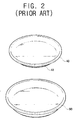
- an auxiliary tray 40 is placed on the rotating tray 90.
- the auxiliary tray 40 is formed with a size and a shape that mean that it can be accommodated in the rotating tray 90.
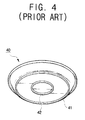
- the auxiliary tray 40 has a pair of ring-shaped ribs 41, 42 on its underside.
- the ribs 41, 42 serve to support the auxiliary tray 40 on the rotating tray 90.
- the auxiliary tray 40 is commonly manufactured from aluminium with its upper surface coated with teflon and its lower surface is with silicon.
- the user loads a food item, such as a pizza, on the auxiliary tray 40 and then places the auxiliary tray 40 on the rotating tray 90. Then, he operates the microwave oven 10 to cook the food item on the auxiliary tray 40. After the cooking is completed, the user takes the auxiliary tray 40 out of the cooking chamber 60.
- the spaces 45 and 46 formed between the ribs 41, 42 and the upper bottom of the rotating tray 90 are heated. Then, the pressure in the spaces 45, 46 becomes very low after the cooking has been completed. Consequently, the auxilary tray 40 becomes stuck to the rotating tray 90, making it hard to detach the auxiliary tray 40 from the rotating tray 90.
- a tray according to the present invention is characterised in that the rib has an aperture through it.
- the tray may be in the form of, for example, a plate, a dish or a bowl.
- a tray according to the present invention may have a plurality of elastomeric ribs on its underside, wherein each rib has an aperture through it.
- the ribs are concentric.
- the ribs need not be circular.
- the or each aperture comprise a gap in a rib.
- the apertures may alternatively be holes or the spaces between small axial projections from a rib.
- rotating tray rotated by a motor is installed in the cooking chamber of a microwave oven and the auxiliary tray 140 is placed on the rotating tray.
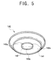
- the auxiliary tray 140 has a pair of ring-shaped ribs 141, 142 attached coaxially on its underside.
- the ribs 141, 142 serve to support the auxiliary tray 140 on the rotating tray.
- the auxiliary tray 140 is manufactured from aluminium with its upper surface coated with teflon and lower surface coated with silicon.
- the ribs 141, 142 are manufactured from rubber.
- the inner rib 142 has three air vents 142a formed by cutting a part of the inner rib 142 away.
- the air vents 142a spaced apart by 120°.
- the air vents 142a open the space bounded by the inner rib 142, the top of the rotating tray and the bottom of the auxiliary tray 140.
- the inner rib 142 has air vents 142a like those in the above-described embodiment, and the outer rib 141 also has air vents 141a.
- the air vents 141a open the space bounded the outer rib 141, the inner rib 142, the top of the rotating tray and the bottom of the auxliliary tray 140.
- the auxiliary tray 149 does not become stuck to the rotating tray because the air vents 141a, 141b in the ribs 141, 142 mean that the air in the spaces within the broken rings 141, 142 remains at ambient pressure.
- the weight of the food item is mainly concentrated on the central area of the auxiliary tray 140, so gaps in the outer ring 141 are not necessary in all cases.
- the air vents 141a, 142a are formed by cutting away parts of the ribs 141, 142.
- the air vents 141a, 142a can be formed in a variety of manners and shapes. For example, if a protrusion protruding downward from a part of the ribs 141, 142 is formed, the ribs 141, 142 do not airtightly contact the top of the rotating tray.
- the air vents can be formed by forming an aperture in a part of the ribs 141, 142.
Landscapes
- Engineering & Computer Science (AREA)
- Food Science & Technology (AREA)
- Electric Ovens (AREA)
- Cookers (AREA)
Applications Claiming Priority (2)
| Application Number | Priority Date | Filing Date | Title |
|---|---|---|---|
| KR19980022617 | 1998-06-16 | ||
| KR9822617 | 1998-06-16 |
Publications (1)
| Publication Number | Publication Date |
|---|---|
| EP0966181A2 true EP0966181A2 (de) | 1999-12-22 |
Family
ID=19539704
Family Applications (1)
| Application Number | Title | Priority Date | Filing Date |
|---|---|---|---|
| EP99300081A Withdrawn EP0966181A2 (de) | 1998-06-16 | 1999-01-06 | Hilfreiche Schale für Mikrowellengeräte |
Country Status (3)
| Country | Link |
|---|---|
| EP (1) | EP0966181A2 (de) |
| JP (1) | JP3053804B2 (de) |
| CN (1) | CN1239208A (de) |
Families Citing this family (5)
| Publication number | Priority date | Publication date | Assignee | Title |
|---|---|---|---|---|
| KR100625897B1 (ko) | 2000-01-13 | 2006-09-20 | 마크스 가부시기가이샤 | 못박는 기계 |
| JP3448596B2 (ja) | 2001-04-10 | 2003-09-22 | 株式会社タカノ | 電子レンジ調理用の容器の蓋とトレイ |
| CN1299063C (zh) * | 2003-02-21 | 2007-02-07 | 乐金电子(天津)电器有限公司 | 微波炉的腔体结构 |
| JP5721879B1 (ja) * | 2014-03-25 | 2015-05-20 | 博繁 河野 | パン・菓子用の食品調理容器及びパン・菓子用の蓋付食品調理容器 |
| WO2016174736A1 (ja) * | 2015-04-28 | 2016-11-03 | サンアロー株式会社 | パン・菓子用の食品調理容器及びパン・菓子用の蓋付食品調理容器 |
-
1999
- 1999-01-06 EP EP99300081A patent/EP0966181A2/de not_active Withdrawn
- 1999-01-13 JP JP11007047A patent/JP3053804B2/ja not_active Expired - Fee Related
- 1999-01-15 CN CN 99100179 patent/CN1239208A/zh active Pending
Non-Patent Citations (1)
| Title |
|---|
| None |
Also Published As
| Publication number | Publication date |
|---|---|
| JP2000005057A (ja) | 2000-01-11 |
| CN1239208A (zh) | 1999-12-22 |
| JP3053804B2 (ja) | 2000-06-19 |
Similar Documents
| Publication | Publication Date | Title |
|---|---|---|
| US5365833A (en) | Pizza baking pan | |
| US2961520A (en) | Domestic appliance | |
| US4335289A (en) | Microwave oven | |
| US20070221651A1 (en) | Cooking vessel with lid | |
| JPS59501614A (ja) | 断熱調理器具 | |
| US20020129714A1 (en) | Cooking apparatus | |
| EP1392082B1 (de) | Heizelemente bei einem Mikrowellenofen | |
| EP1441568B1 (de) | Mikrowellenherd | |
| EP0573750B1 (de) | Mikrowellenofen | |
| EP0966181A2 (de) | Hilfreiche Schale für Mikrowellengeräte | |
| GB2090110A (en) | Microwave oven | |
| US20040000545A1 (en) | Microwave oven, and guide roller, cooking tray and dish for use in microwave oven | |
| EP0132080B1 (de) | Traggestell für einen Mikrowellenherd | |
| JPH01184332A (ja) | 調理器 | |
| KR102188704B1 (ko) | 스마트 팔각불판 시스템 | |
| KR20020030653A (ko) | 전자레인지의 그릴요리용 랙 | |
| GB2171580A (en) | Stand for use in a microwave oven | |
| EP1372357A2 (de) | Gargutträgern für Mikrowellenofen und Mikrowellenofen versehen mit dergleichen | |
| KR200196651Y1 (ko) | 고기 구이판 | |
| CN215914133U (zh) | 锅具和烹饪器具 | |
| US9035225B1 (en) | Microwave cookware | |
| US20240179811A1 (en) | Cooking assembly for a microwave oven | |
| KR19980018846U (ko) | 다기능 전자렌지의 이중 트레이 구조 | |
| KR100265634B1 (ko) | 전자렌지의선반조립구조 | |
| KR200244102Y1 (ko) | 다기능 전자렌지의 하히터 커버 설치구조 |
Legal Events
| Date | Code | Title | Description |
|---|---|---|---|
| PUAI | Public reference made under article 153(3) epc to a published international application that has entered the european phase |
Free format text: ORIGINAL CODE: 0009012 |
|
| AK | Designated contracting states |
Kind code of ref document: A2 Designated state(s): AT BE CH CY DE DK ES FI FR GB GR IE IT LI LU MC NL PT SE |
|
| AX | Request for extension of the european patent |
Free format text: AL;LT;LV;MK;RO;SI |
|
| STAA | Information on the status of an ep patent application or granted ep patent |
Free format text: STATUS: THE APPLICATION IS DEEMED TO BE WITHDRAWN |
|
| 18D | Application deemed to be withdrawn |
Effective date: 20010801 |