EP0966320B2 - Homogenisierungsventil - Google Patents
Homogenisierungsventil Download PDFInfo
- Publication number
- EP0966320B2 EP0966320B2 EP98909117A EP98909117A EP0966320B2 EP 0966320 B2 EP0966320 B2 EP 0966320B2 EP 98909117 A EP98909117 A EP 98909117A EP 98909117 A EP98909117 A EP 98909117A EP 0966320 B2 EP0966320 B2 EP 0966320B2
- Authority
- EP
- European Patent Office
- Prior art keywords
- valve
- inches
- members
- homogenization
- homogenizer
- Prior art date
- Legal status (The legal status is an assumption and is not a legal conclusion. Google has not performed a legal analysis and makes no representation as to the accuracy of the status listed.)
- Expired - Lifetime
Links
- 238000000265 homogenisation Methods 0.000 title claims abstract description 61
- 239000012530 fluid Substances 0.000 claims description 38
- 238000000034 method Methods 0.000 claims description 12
- 238000005086 pumping Methods 0.000 claims description 4
- 238000002156 mixing Methods 0.000 abstract description 13
- 238000013461 design Methods 0.000 abstract description 11
- 244000145845 chattering Species 0.000 abstract description 3
- 230000001066 destructive effect Effects 0.000 abstract 1
- 235000013336 milk Nutrition 0.000 description 15
- 239000008267 milk Substances 0.000 description 15
- 210000004080 milk Anatomy 0.000 description 15
- 230000008569 process Effects 0.000 description 6
- 235000020603 homogenised milk Nutrition 0.000 description 5
- 230000000694 effects Effects 0.000 description 4
- 235000021243 milk fat Nutrition 0.000 description 4
- 239000006185 dispersion Substances 0.000 description 3
- 239000000839 emulsion Substances 0.000 description 3
- 238000002474 experimental method Methods 0.000 description 3
- 230000001965 increasing effect Effects 0.000 description 3
- 230000008901 benefit Effects 0.000 description 2
- 238000010276 construction Methods 0.000 description 2
- 230000007246 mechanism Effects 0.000 description 2
- 238000011160 research Methods 0.000 description 2
- 230000001133 acceleration Effects 0.000 description 1
- WYTGDNHDOZPMIW-RCBQFDQVSA-N alstonine Natural products C1=CC2=C3C=CC=CC3=NC2=C2N1C[C@H]1[C@H](C)OC=C(C(=O)OC)[C@H]1C2 WYTGDNHDOZPMIW-RCBQFDQVSA-N 0.000 description 1
- 229940069428 antacid Drugs 0.000 description 1
- 239000003159 antacid agent Substances 0.000 description 1
- 238000013459 approach Methods 0.000 description 1
- 230000015572 biosynthetic process Effects 0.000 description 1
- 238000000576 coating method Methods 0.000 description 1
- 238000004891 communication Methods 0.000 description 1
- 239000006071 cream Substances 0.000 description 1
- 230000003247 decreasing effect Effects 0.000 description 1
- 230000001419 dependent effect Effects 0.000 description 1
- 230000001939 inductive effect Effects 0.000 description 1
- 239000007788 liquid Substances 0.000 description 1
- 230000002093 peripheral effect Effects 0.000 description 1
- 230000021715 photosynthesis, light harvesting Effects 0.000 description 1
- 239000000049 pigment Substances 0.000 description 1
- 230000009467 reduction Effects 0.000 description 1
- 229920002545 silicone oil Polymers 0.000 description 1
- 241000894007 species Species 0.000 description 1
- 238000011144 upstream manufacturing Methods 0.000 description 1
- 230000000007 visual effect Effects 0.000 description 1
Images


Classifications
-
- B—PERFORMING OPERATIONS; TRANSPORTING
- B01—PHYSICAL OR CHEMICAL PROCESSES OR APPARATUS IN GENERAL
- B01F—MIXING, e.g. DISSOLVING, EMULSIFYING OR DISPERSING
- B01F25/00—Flow mixers; Mixers for falling materials, e.g. solid particles
- B01F25/40—Static mixers
- B01F25/44—Mixers in which the components are pressed through slits
- B01F25/442—Mixers in which the components are pressed through slits characterised by the relative position of the surfaces during operation
- B01F25/4421—Mixers in which the components are pressed through slits characterised by the relative position of the surfaces during operation the surfaces being maintained in a fixed position, spaced from each other, therefore maintaining the slit always open
-
- B—PERFORMING OPERATIONS; TRANSPORTING
- B01—PHYSICAL OR CHEMICAL PROCESSES OR APPARATUS IN GENERAL
- B01F—MIXING, e.g. DISSOLVING, EMULSIFYING OR DISPERSING
- B01F25/00—Flow mixers; Mixers for falling materials, e.g. solid particles
- B01F25/40—Static mixers
- B01F25/44—Mixers in which the components are pressed through slits
- B01F25/441—Mixers in which the components are pressed through slits characterised by the configuration of the surfaces forming the slits
- B01F25/4412—Mixers in which the components are pressed through slits characterised by the configuration of the surfaces forming the slits the slits being formed between opposed planar surfaces, e.g. pushed again each other by springs
- B01F25/44121—Mixers in which the components are pressed through slits characterised by the configuration of the surfaces forming the slits the slits being formed between opposed planar surfaces, e.g. pushed again each other by springs with a plurality of parallel slits, e.g. formed between stacked plates
Definitions
- Homogenization is the process of breaking down and blending components within a fluid.
- One familiar example is milk homogenization in which milk fat globules are broken-up and distributed into the bulk of the milk.
- Homogenization is also used to process other emulsions such as silicone oil and process dispersions such as pigments, antacids, and some paper coatings.
- the most common device for performing homogenization is a homogenization valve.
- the emulsion or dispersion is introduced under high pressure into the valve, which functions as a flow restrictor to generate intense turbulence.
- the high pressure fluid is forced out through a usually narrow valve gap into a lower pressure environment.
- each valve member the wall between the central hole and the grooves is chamfered to provide knife edges.
- Each knife edge forms a valve seat spaced a small distance from an opposed valve surface on the adjacent valve member. In this design, an optimal valve spacing can be maintained for any flow rate; higher flow rates are accommodated simply by adding more valve members to the stack.
- homogenization valve design is generally driven by two concerns. On one hand, there is a desire for consistently well homogenized products. Milk shelf life is limited by the time between homogenization and when creaming begins to affect visual appearance. This is the reverse of the homogenization process in which the milk fat again becomes separated from the bulk milk. The second, sometimes conflicting, concern is the cost of homogenization, which is largely dictated by the consumed energy.
- the size of the milk fat globules in the homogenized milk determines the speed at which creaming occurs. Thus, in order to extend shelf life, it is important that the homogenization process yields small fat globules in the homogenized milk. The smaller the fat globules, the more dispersed is the fat, and the longer it takes for enough of the fat globules to coalesce and produce noticeable creaming. More complete homogenization, however, generally requires higher pressures, which undermines the second concern since higher pressures require larger energy inputs.
- the standard deviation in the size of the fat globules in the homogenized milk also plays a role in determining the milk's shelf life.
- Some valve designs produce generally small fat globules, which suggests a long shelf life. Because of the characteristics of the regions surrounding the valve gap, however, some fat globules can largely or entirely escape the homogenization process as they pass through the valve. These larger fat globules in the homogenized milk contain a relatively large amount of fat, and they cream rapidly compared to very small fat globules. Thus, even though the average size of the fat globules may be small in a given sample of milk, the shelf life may still be relatively short due to the existence of a relatively few large globules.
- Embodiments of the present invention are directed to an improved valve member design that is applicable to the design disclosed in the Pandolfe series of patents. More generally, the principals of the present invention may be applied to other homogenization valve configurations.
- DE 3 818 237 A1 discloses a high pressure homogenizing device for separating cells.
- the object of the invention is to provide a homogenizer valve and a homogenization method with a better performance.
- the object of the invention is met by a homogenizer valve in accordance with claim 1 and a homogenization method of claim 10.
- embodiments of the invention provide a homogenizer valve in which flow restricting surfaces oppose each other on either side of a laterally extended valve gap.
- the downstream terminations of the opposed surfaces are staggered with respect to each other by at least a distance necessary to inhibit chattering of the valve.
- downstream terminations of the opposed surfaces according to the invention should be staggered by at least a height of the valve gap for stability, but staggered not more than approximately ten times the gap height for complete homogenization.
- Experimentation with milk homogenization using gaps of less than 0.003 inches (7.6 x 10 -5 m) in practice between 0. 0010 and 0.0020 inches (2.5 x 10 -5 m - 5.1 x 10 -5 m), indicates that the staggering or overlap should be greater than approximately 0.0010 inches(2.5 x 10 -5 m) but always less than 0.025 inches(6.4 x 10 -4 m) .
- the preferred homogenizer valve comprises a stack of annularly-shaped valve members defining a central hole and axial fluid conduits. This configuration is applicable in commercial applications requiring flow rates of 500 gal/hour (1893 l/min) and greater.
- Annular springs are used to align adjoining pairs of the valve members, the springs fitting in spring-grooves formed in the valve members. Homogenization occurs as the fluid passes between the central hole and the axial fluid conduits through the intervening annular valve gaps.
- one of the opposed surfaces in each adjoining pair of the valve members is between (0.015 to 0.020 inches) 3.8 x 10 -4 - 5.1 x 10 -4 m, but always less than (0.06 inches) 1.5 x 10 -3 m.
- the valve may have a stack of annularly-shaped valve members defining a central hole and axial fluid conduits with homogenization occurring as the fluid passes between the central hole and the axial fluid conduits though intervening annular valve gaps defined by opposed valve surfaces and valve seats, the gaps being less than (0.003 inches) 7.6 x 10 -5 m, in which the downstream terminations of the valve surfaces have an overlap that is less than (0.025 inches) 6.4 x 10 -4 m whereby chattering of the valve is inhibited; and annular springs that align adjoining pairs of the valve members, the springs fitting in spring-grooves formed in the valve members.
- the following steps can be carried out: pumping a fluid between stacked valve members providing opposed valve surfaces and valve seats; maintaining the valve members in alignment with annular springs that fit in spring-grooves formed in the valve members; separating the valve seats from the valve surfaces by a distance of less than(0.003 inches) 7.6 x 10 -5 m; overlapping a downstream termination of the valve surfaces with respect to the valve seat by a distance necessary to avoid chatter; and limiting the overlap to less than approximately (0.025 inches) 6.4 x 10 -4 m.
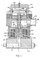
- Fig. 1 is a cross-sectional view of a homogenization system that is related to the design disclosed in the Pandolfe patents.
- the system includes valve members 100 constructed according to the principles of the present invention, many of the details of these members being better understood with reference to Fig. 2 .
- an inlet port 112 formed in an inlet flange 114, conveys a high pressure fluid to a valve member stack 116.
- the high pressure fluid is introduced into an inner chamber 118 defined by the central holes 103 formed through the generally annular valve members 100.
- the high pressure fluid is then expressed through valve gaps 102 into a low pressure chamber 120 that is defined by the axial ports 122 through the valve members 100 and the annular grooves 124 in the valve members.
- the fluid passing into the low pressure chamber enters a discharge port 126 in a discharge flange assembly 130.
- the stack 116 of valve members 100 is sealed against the inlet flange 114 via a base valve member 132.
- the topmost valve member engages a top valve plug 140 that seals across the inner chamber 118.
- This top valve plug 140 is hydraulically or pneumatically urged by actuator assembly 142, which comprises an actuator body 144 surrounding an actuator piston 146 sealed to it via an O ring 148.
- the piston 146 is connected to the top plug 140 via the actuator rod 150.
- An actuator guide plate 152 sits between the body 144 and the discharge flange assembly 130.
- the base valve member 132 and other valve members 100 are aligned with respect to each other and maintained in the stack formation by serpentine valve springs 134 that are confined within cooperating spring-grooves 136, 138 formed in the otherwise flat peripheral rim surfaces of each valve member 100.
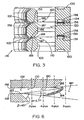
- Fig. 3 is a cross-sectional view of the valve members around the valve gaps, showing a prior art valve gap region 160 and the valve gap region 170 in the inventive homogenization valve.
- the height of both gaps is preferably between 0.0015 and 0.0020 inches (3.8 x 10 -5 m - 5.1 x 10 -5 m), usually about 0. 0018 inches (4.6 x 10 -5 m) , but in any event less than 0.003 inches.
- This dimension is defined as the vertical distance between the valve seat or land 158 and the opposed, largely flat, valve surface 156. Experimention has shown that the gap should not be simply increased beyond 0.003 inches (7.6 x 10 -5 m) to obtain higher flow rates since such increases will lead to lower homogenization efficiencies.
- the valve seat is a knife-edge configuration.
- the valve seat 158 is chamfered at 45° angle sloping toward the valve surface 156.
- the valve seat 158 is flat across a distance of ideally approximately 0.015 to 0.020 inches (3. 8 x 10 -4 m - 5.1 x 10 -4 m), but less than 0.06 inches (1.5 x 10 -3 m) .
- the valve seat slopes away from the valve surface at an angle from 5 to 90°, 45° in the illustrated embodiment.
- valve gap region 160 fluid passing through the valve gap 102 is accelerated as it passes over the relatively short valve seat or land 158.
- the adjoining valve member presents a flat valve surface 156 that extends radially outward, parallel to the direction of fluid flow through the gap 102.
- the total length of the valve surface extending radially from the land is not a closely controlled tolerance but tends to be relatively long, approximately 0.055 inches (1.4 x 10 -3 m) in length.
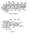
- Fig. 4 illustrates the flow conditions for fluid passing through the prior art valve gap region 160.
- flow between the land 158 and the valve surface 156 is entirely laminar 180. Little homogenization occurs in this space, but the fluid is highly accelerated at this point.
- the portion of the fluid 180 in laminar flow reduces with increasing distance from the gap 102.
- the layers away from the valve surface 156 are progressively converted into turbulent three dimensional high and low speed mixing layers 182 in which the laminar characteristics do not exist.
- the energy dissipation in the turbulent mixing layer peaks and a homogenization front or zone 184 forms in which the mixing layers merge and become fully turbulent. This is where most of the homogenization occurs. It is here that the energy contained in the fluid's pressure and speed is converted into the disruption of the milk fat globules or the blending of components in the emulsions or dispersions, generally.
- the location of the homogenization front can be defined two ways. For a common valve gap for milk homogenization of 0.0018 inches(4.6 x 10 -5 m) , the homogenization front is centered at approximately 0.012 inches (3.1 x 10 -4 m) from the end 187 of the land surface. More generally, however, the homogenization front stretches across a distance of approximately 6 to 10 times the size of the gap. This relationship can be generalized to other valve configurations.
- valve gap region 170 embodying the present invention the ends of the opposed surfaces that define the gap 102 are still staggered with respect to each other.
- the valve surface 156 terminates 188 much closer to the end of the land 158. There is some overlap, but the length of the overlap is closely controlled.
- Fig. 5 shows the flow conditions for the fluid emerging from valve gap 102 when no overlap exists.
- the region of laminar flow 180 exhibits a triangular cross-section extending away from the valve gap, decreasing on its top and bottom moving away from the ends of the valve surfaces.
- the homogenization zone or front 184 converges with the turbulent mixing layers 182. Virtually all fluid that exits from the valve passes through this zone existing at approximately 5 gap distances and is completely homogenized.
- the wall-effects from the valve surface 156 do not extend laminar flow 180 beyond the zone 184. Instead, the early truncation of surface 156 completely disturbs the laminar flow field 180, allowing the homogenization zone 184 to fully encompass the fluid exiting from the gap 102.
- valve surface 156 and valve seat 158 wall effects from the valve surface 156 and valve seat 158 will not otherwise arise as long as the chamfering angle ⁇ , which is illustrated as 45 degrees, does not approach the angle of divergence of the turbulent mixing layer, ⁇ , which is 5.7 degrees.
- the angle ⁇ is at least 10 degrees to avoid the risk of any attachment of the laminar flow to the wall.
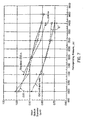
- Fig. 7 is a plot presenting the results of experiments correlating mean globule diameter in homogenized milk as a function of pressure for valves using different overlaps.
- Valve overlaps between 0.025 inches(6.4x 10 -4 m) ( ⁇ ) , 0.040 inches(1.02 x 10 -3 m) ( ⁇ ) and the standard 0.055 inches(1.4 x 10 -3 m) ( ⁇ ) exhibit essentially the same performance.
- a mean globule size of approximately 0.90 micrometers is produced between 1,100-1,200 psi (7584 kPa - 8274 kpa homogenizing pressure.
- Fig. 8 shows the results of experimentation using a laboratory setup with a corresponding low flow rate.
- the plot is of droplet diameter as a function of overlap or overhang for three homogenizing pressures (1000 psi(6894kPa) ( ⁇ ), 1200 psi (8274kPa) ( ⁇ ), and 1400 psi (9652kPa)( ⁇ )) using filled milk at a flow rate of 40 gallons per hour(151). Even at this low flow rate, a reduction in overlap yields better homogenization, agreeing with the experiments under commercial conditions.
Landscapes
- Chemical & Material Sciences (AREA)
- Dispersion Chemistry (AREA)
- Chemical Kinetics & Catalysis (AREA)
- Dairy Products (AREA)
- Lift Valve (AREA)
- Soy Sauces And Products Related Thereto (AREA)
Claims (12)
- Homogenisierungsventil mit Durchflussbegrenzungsflächen (156, 158), die einander an beiden Seiten einer sich lateral erstreckenden Ventilöffnung (102) gegenüberliegen, dadurch gekennzeichnet, dass stromabwärts liegende Enden (188, 187) der gegenüberliegenden Flächen versetzt angeordnet sind und dass die stromabwärtsseitigen Enden (188, 187) der gegenüberliegenden Flächen jeweils in dem gleichen Winkel (β) von 5 bis 90° zu jeweiligen Ebenen, die durch die gegenüberliegenden durchflussbegrenzenden Flächen (156, 158) festgelegt werden, geneigt sind, wobei die stromabwärtsseitigen Enden der gegenüberliegenden Flächen um wenigstens eine Höhe der Ventilöffnung versetzt angeordnet sind, aber nicht mehr als etwa zehn Mal die Öffnungshöhe.
- Homogenisierungsventil nach Anspruch 1, wobei eine Höhe der Ventilöffnung zwischen 0,0010 und 0,0020 Zoll (2,5x 10⁻⁵ - 5,1 x 10⁻⁵ m) beträgt, und die stromabwärtsseitigen Enden der gegenüberliegenden Flächen um einen Abstand von weniger als 6,35 x 10⁻⁴ m (0,025 Zoll) versetzt angeordnet sind.
- Homogenisierungsventil nach einem der Ansprüche 1 bis 2 mit einem Stapel ringförmiger Ventilelemente (100), die eine zentrale Öffnung (118) und axiale Fluidkanäle (120) festlegen, wobei die Homogenisierung erfolgt, wenn das Fluid zwischen der zentralen Öffnung und den axialen Fluidkanälen durch die dazwischenliegenden ringförmigen Ventilöffnungen (102) hindurchtritt, wobei die gegenüberliegenden Flächen durch jeweils benachbarte Paare von Ventilelementen gebildet werden.
- Homogenisierungsventil nach einem der Ansprüche 1 bis 3, wobei das Homogenisierungsventil bei der Verwendung so angeordnet wird, dass es eine Durchflussrate von wenigstens 1893 1/h (500 gal/h) aufweist.
- Homogenisierungsventil nach einem der Ansprüche 3 oder 4, außerdem mit ringförmigen Federn (134), die dazu verwendet werden, benachbarte Paare von Ventilelementen auszurichten, wobei die Federn in in den Ventilelementen ausgebildete Federnuten (136,138) passen.
- Homogenisierungsventil nach Anspruch 3, wobei eine der gegenüberliegenden Fläche jedes benachbarten Paares von Ventilelementen eine Gesamtlänge von etwa 3,8 x 10⁻⁴- 5,1 x 10⁻⁴ m (0,015 bis 0,020 Zoll) aufweist.
- Homogenisierungsventil nach einem der vorhergehenden Ansprüche mit:einem Stapel ringförmiger Ventilelemente (100), die eine zentrale Öffnung (118) und axiale Fluidkanäle (120) festlegen, wobei die Homogenisierung erfolgt, wenn das Fluid zwischen der zentralen Öffnung und den axialen Fluidkanälen durch die durchflussbeschränkenden gegenüberliegenden Ventilflächen (156, 158) durchtritt, wobei die Ventilöffnungen kleiner sind als 0,003 Zoll (7,6 x 10⁻⁵ m), und wobei die stromabwärtsseitigen Enden (188, 187) einen Überlapp aufweisen, der kleiner ist als 6,4 x 10⁻⁴ m (0,025 Zoll); undringförmigen Federn (134), die benachbarte Paare der Ventilelemente ausrichten, wobei die Federn in in den Ventilelementen ausgebildete Federnuten (136, 138) passen.
- Homogenisierungsventil nach Anspruch 7, wobei die stromabwärtsseitigen Enden der Ventilflächen die Ventilsitze um wenigstens eine Höhe des Ventils überlappen.
- Homogenisierungsventil nach Anspruch 7, wobei die Ventilsitze eine Länge aufweisen, die kleiner ist als 1,5 x 10⁻³ m (0,06 Zoll).
- Homogenisierungsverfahren mit:Pumpen eines Fluides durch ein Ventil mit einer gegenüberliegenden Ventilfläche (156) und Ventilsitz (158) in einer Umgebung mit niedrigem Druck; gekennzeichnet durch versetztes Anordnen eines stromabwärtsseitigen Endes (188) der Ventilfläche relativ zu einem stromabwärtsseitigen Ende (187) des Ventilsitzes um wenigstens den Abstand zwischen dem Ventilsitz und der Ventilfläche und Begrenzen der versetzten Anordnung der Enden der Ventilflächen auf weniger als etwa zehn Mal den Abstand zwischen dem Ventilsitz und der Ventilfläche; und Abwinkeln des stromabwärtsseitigen Endes (188) der Ventilfläche und des stromabwärtsseitigen Endes (187) des Ventilsitzes in dem gleichen Winkel (β) von 5 bis 90° zu entsprechenden Ebenen, die jeweils durch die gegenüberliegenden Ventilfläche (156) bzw. Ventilsitz (158) festgelegt werden.
- Verfahren nach Anspruch 10, außerdem mit:Beabstanden der Ventilfläche von dem Ventilsitz um weniger als 7,6 x 10⁻⁵ m (0,003 Zoll); und Begrenzen der versetzten Anordnung des Endes der Ventilfläche relativ zu dem Ventilsitz auf weniger als etwa 6,4 x 10⁻⁴ m (0,025 Zoll).
- Homogenisierungsverfahren nach einem der Ansprüche 10 bis 11, wobei der Pumpschritt das Pumpen eines Fluides zwischen versetzt angeordneten Ventilelementen (100), die die gegenüberliegenden Ventilflächen (156) und Ventilsitze (158) zur Verfügung stellen, umfasst; und wobei außerdem die Ventilsitze durch ringförmige Federn (134), die in in den Ventilelementen ausgebildete Ventilnuten (136, 138) passen, ausgerichtet gehalten werden.
Priority Applications (2)
| Application Number | Priority Date | Filing Date | Title |
|---|---|---|---|
| DK98909117T DK0966320T3 (da) | 1997-03-13 | 1998-03-11 | Hormogeniseringsventil |
| DE69825569T DE69825569T3 (de) | 1997-03-13 | 1998-03-11 | Homogenisierungsventil |
Applications Claiming Priority (3)
| Application Number | Priority Date | Filing Date | Title |
|---|---|---|---|
| US816278 | 1997-03-13 | ||
| US08/816,278 US5749650A (en) | 1997-03-13 | 1997-03-13 | Homogenization valve |
| PCT/US1998/004775 WO1998040156A1 (en) | 1997-03-13 | 1998-03-11 | Homogenization valve |
Publications (3)
| Publication Number | Publication Date |
|---|---|
| EP0966320A1 EP0966320A1 (de) | 1999-12-29 |
| EP0966320B1 EP0966320B1 (de) | 2004-08-11 |
| EP0966320B2 true EP0966320B2 (de) | 2011-03-23 |
Family
ID=25220153
Family Applications (1)
| Application Number | Title | Priority Date | Filing Date |
|---|---|---|---|
| EP98909117A Expired - Lifetime EP0966320B2 (de) | 1997-03-13 | 1998-03-11 | Homogenisierungsventil |
Country Status (11)
| Country | Link |
|---|---|
| US (2) | US5749650A (de) |
| EP (1) | EP0966320B2 (de) |
| JP (1) | JP4163261B2 (de) |
| CN (1) | CN1120744C (de) |
| AT (1) | ATE273062T1 (de) |
| AU (1) | AU724832B2 (de) |
| CA (1) | CA2283930C (de) |
| DE (1) | DE69825569T3 (de) |
| DK (1) | DK0966320T3 (de) |
| ES (1) | ES2226104T3 (de) |
| WO (1) | WO1998040156A1 (de) |
Families Citing this family (27)
| Publication number | Priority date | Publication date | Assignee | Title |
|---|---|---|---|---|
| US5749650A (en) † | 1997-03-13 | 1998-05-12 | Apv Homogenizer Group, A Division Of Apv North America, Inc. | Homogenization valve |
| SE509103C2 (sv) * | 1997-04-22 | 1998-12-07 | Tetra Laval Holdings & Finance | Homogeniseringsventil |
| US6305836B1 (en) * | 1999-07-09 | 2001-10-23 | Apv North America, Inc. | Force absorbing homogenization valve |
| US6238080B1 (en) | 1999-07-09 | 2001-05-29 | Apv North America, Inc. | Homogenization valve with outside high pressure volume |
| US6244739B1 (en) | 1999-07-09 | 2001-06-12 | Apv North America, Inc. | Valve members for a homogenization valve |
| DE19940994B4 (de) * | 1999-08-28 | 2004-02-26 | Clausthaler Umwelttechnikinstitut Gmbh, (Cutec-Institut) | Verfahren zum Abbau von Klärschlamm |
| JP4414077B2 (ja) * | 2000-09-08 | 2010-02-10 | 本田技研工業株式会社 | オートマチックトランスミッション用チョークバルブ |
| US6502979B1 (en) * | 2000-11-20 | 2003-01-07 | Five Star Technologies, Inc. | Device and method for creating hydrodynamic cavitation in fluids |
| DE10333922B4 (de) * | 2003-07-25 | 2005-11-17 | Wella Ag | Bauteile für statische Mikromischer, daraus aufgebaute Mikromischer und deren Verwendung zum Mischen, zum Dispergieren oder zur Durchführung chemischer Reaktionen |
| ITPR20030089A1 (it) * | 2003-10-15 | 2005-04-16 | Niro Soavi Spa | Valvola di omogeneizzazione. |
| US20070140042A1 (en) * | 2004-06-04 | 2007-06-21 | Gerhard Schanz | Multicomponent packaging with static micromixer |
| CN100443152C (zh) * | 2005-11-02 | 2008-12-17 | 财团法人工业技术研究院 | 高压均质装置的导流构造 |
| SE531925C2 (sv) | 2008-01-29 | 2009-09-08 | Tetra Laval Holdings & Finance | Homogeniseringsventil |
| FR2939423B1 (fr) * | 2008-12-09 | 2011-12-09 | Yves Lecoffre | Procede et dispositif de traitement d'au moins un compose transporte dans un liquide |
| SE535549C2 (sv) * | 2010-12-22 | 2012-09-18 | Tetra Laval Holdings & Finance | Homogeniseringsventil |
| US9399201B1 (en) | 2012-09-28 | 2016-07-26 | Fristam Pumps, USA | Homogenizer for reducing the size of particles in fluids |
| ITPR20130081A1 (it) * | 2013-10-21 | 2015-04-22 | Gea mechanical equipment italia spa | Valvola omogeneizzante, in particolare per applicazione a fluidi fibrosi |
| BR112017022241B1 (pt) * | 2015-04-17 | 2022-04-12 | Bühler AG | Dispositivo para misturar e processo para dispersão de substâncias em um dispositivo |
| CA2972790A1 (en) | 2016-07-11 | 2018-01-11 | Exceldor Foods Ltd. | Oil-in-water emulsions for meat and poultry products and methods of producing same |
| US10458553B1 (en) | 2017-06-05 | 2019-10-29 | Vistadeltek, Llc | Control plate for a high conductive valve |
| US11248708B2 (en) | 2017-06-05 | 2022-02-15 | Illinois Tool Works Inc. | Control plate for a high conductance valve |
| CN114658860B (zh) * | 2017-06-05 | 2024-11-29 | 伊利诺斯工具公司 | 用于高传导性阀的控制板 |
| US10364897B2 (en) * | 2017-06-05 | 2019-07-30 | Vistadeltek, Llc | Control plate for a high conductance valve |
| DE102021004243B4 (de) | 2021-08-20 | 2023-11-30 | Gea Mechanical Equipment Italia S.P.A. | Ventil und Verwendung eines Ventils |
| IT202300000933A1 (it) | 2023-01-23 | 2024-07-23 | Gea Mech Equipment Italia S P A | Valvola multi-gap e apparato omogeneizzante comprendente detta valvola multi-gap |
| DE102023002857B4 (de) | 2023-07-14 | 2026-05-07 | Hst Maschinenbau Gmbh | Homogenisierventil |
| DE102024001822A1 (de) | 2024-06-06 | 2025-12-11 | Gea Mechanical Equipment Italia S.P.A. | Homogenisierventil |
Citations (6)
| Publication number | Priority date | Publication date | Assignee | Title |
|---|---|---|---|---|
| GB2039225A (en) † | 1978-12-21 | 1980-08-06 | Showa Denko Kk | Mixing device |
| US4383769A (en) † | 1980-01-29 | 1983-05-17 | Gaulin Corporation | Homogenizing apparatus and method |
| DE3818237A1 (de) † | 1988-05-28 | 1989-11-30 | Bran & Luebbe | Hochdruckhomogenisator |
| US4952067A (en) † | 1989-11-13 | 1990-08-28 | Dallas Tolbert H | Homogenizing apparatus |
| US5575561A (en) † | 1994-01-27 | 1996-11-19 | Rohwer; Gary L. | In-line mixer for dispersions |
| WO1998040156A1 (en) † | 1997-03-13 | 1998-09-17 | Apv Homogenizer Group | Homogenization valve |
Family Cites Families (22)
| Publication number | Priority date | Publication date | Assignee | Title |
|---|---|---|---|---|
| US366169A (en) * | 1887-07-05 | John w | ||
| US1533843A (en) * | 1925-04-14 | of london | ||
| US973328A (en) * | 1910-04-02 | 1910-10-18 | Joseph Willmann | Emulsifier. |
| US996704A (en) * | 1910-09-19 | 1911-07-04 | Frank P Cribbins | Machine for homogenizing milk. |
| US1070226A (en) * | 1911-10-23 | 1913-08-12 | Dairy Machinery And Construction Company Inc | Homogenizer. |
| US1070218A (en) * | 1912-06-21 | 1913-08-12 | Joseph Willmann | Homogenizer. |
| US1112594A (en) * | 1912-08-28 | 1914-10-06 | Henry N Brawner Jr | Method or process of homogenizing cream. |
| US1266501A (en) * | 1915-06-14 | 1918-05-14 | Laval Separator Co De | Emulsifier. |
| US1436947A (en) * | 1922-10-26 | 1922-11-28 | E F Comezys | Process for preserving lacteal fluids |
| US2882025A (en) * | 1955-06-16 | 1959-04-14 | Carnation Co | Homogenizing valve |
| US3179385A (en) * | 1961-11-17 | 1965-04-20 | Manton Gaulin Mfg Company Inc | Method and apparatus for processing fluids |
| US3526391A (en) * | 1967-01-03 | 1970-09-01 | Wyandotte Chemicals Corp | Homogenizer |
| US3732851A (en) * | 1971-05-26 | 1973-05-15 | R Self | Method of and device for conditioning steam |
| DE2360392C2 (de) * | 1973-12-04 | 1975-12-04 | Siemens Ag, 1000 Berlin Und 8000 Muenchen | Einrichtung zur Steuerung eines Thyristors |
| US4081863A (en) * | 1975-07-23 | 1978-03-28 | Gaulin Corporation | Method and valve apparatus for homogenizing fluid emulsions and dispersions and controlling homogenizing efficiency and uniformity of processed particles |
| US4160002A (en) * | 1976-06-09 | 1979-07-03 | Janovtchik Viacheslav J | Steam injectors |
| US4205696A (en) * | 1978-09-18 | 1980-06-03 | Innerspace Corporation | Fluid control valve |
| US4352573A (en) * | 1980-01-29 | 1982-10-05 | Gaulin Corporation | Homogenizing method |
| US4533254A (en) * | 1981-04-17 | 1985-08-06 | Biotechnology Development Corporation | Apparatus for forming emulsions |
| US4585357A (en) * | 1984-10-18 | 1986-04-29 | Kazuo Ogata | Homogenizer |
| US4921014A (en) * | 1989-04-27 | 1990-05-01 | Marotta Scientific Controls, Inc. | Noise-reducing valve construction |
| US5451106A (en) * | 1994-08-08 | 1995-09-19 | National Research Council Of Canada | Extensional flow mixer |
-
1997
- 1997-03-13 US US08/816,278 patent/US5749650A/en not_active Expired - Lifetime
-
1998
- 1998-03-11 EP EP98909117A patent/EP0966320B2/de not_active Expired - Lifetime
- 1998-03-11 DK DK98909117T patent/DK0966320T3/da active
- 1998-03-11 DE DE69825569T patent/DE69825569T3/de not_active Expired - Lifetime
- 1998-03-11 AU AU66981/98A patent/AU724832B2/en not_active Expired
- 1998-03-11 AT AT98909117T patent/ATE273062T1/de not_active IP Right Cessation
- 1998-03-11 WO PCT/US1998/004775 patent/WO1998040156A1/en not_active Ceased
- 1998-03-11 CA CA002283930A patent/CA2283930C/en not_active Expired - Lifetime
- 1998-03-11 JP JP53976798A patent/JP4163261B2/ja not_active Expired - Lifetime
- 1998-03-11 CN CN98803288A patent/CN1120744C/zh not_active Expired - Lifetime
- 1998-03-11 ES ES98909117T patent/ES2226104T3/es not_active Expired - Lifetime
- 1998-05-11 US US09/076,297 patent/US5899564A/en not_active Expired - Lifetime
Patent Citations (6)
| Publication number | Priority date | Publication date | Assignee | Title |
|---|---|---|---|---|
| GB2039225A (en) † | 1978-12-21 | 1980-08-06 | Showa Denko Kk | Mixing device |
| US4383769A (en) † | 1980-01-29 | 1983-05-17 | Gaulin Corporation | Homogenizing apparatus and method |
| DE3818237A1 (de) † | 1988-05-28 | 1989-11-30 | Bran & Luebbe | Hochdruckhomogenisator |
| US4952067A (en) † | 1989-11-13 | 1990-08-28 | Dallas Tolbert H | Homogenizing apparatus |
| US5575561A (en) † | 1994-01-27 | 1996-11-19 | Rohwer; Gary L. | In-line mixer for dispersions |
| WO1998040156A1 (en) † | 1997-03-13 | 1998-09-17 | Apv Homogenizer Group | Homogenization valve |
Also Published As
| Publication number | Publication date |
|---|---|
| AU724832B2 (en) | 2000-09-28 |
| CN1120744C (zh) | 2003-09-10 |
| EP0966320A1 (de) | 1999-12-29 |
| CN1250392A (zh) | 2000-04-12 |
| ES2226104T3 (es) | 2005-03-16 |
| JP2001514578A (ja) | 2001-09-11 |
| EP0966320B1 (de) | 2004-08-11 |
| DK0966320T3 (da) | 2004-11-08 |
| CA2283930A1 (en) | 1998-09-17 |
| DE69825569T2 (de) | 2005-09-15 |
| JP4163261B2 (ja) | 2008-10-08 |
| DE69825569D1 (de) | 2004-09-16 |
| DE69825569T3 (de) | 2012-05-10 |
| WO1998040156A1 (en) | 1998-09-17 |
| ATE273062T1 (de) | 2004-08-15 |
| AU6698198A (en) | 1998-09-29 |
| US5899564A (en) | 1999-05-04 |
| CA2283930C (en) | 2006-11-07 |
| US5749650A (en) | 1998-05-12 |
Similar Documents
| Publication | Publication Date | Title |
|---|---|---|
| EP0966320B2 (de) | Homogenisierungsventil | |
| EP0034675B1 (de) | Vorrichtung zum Homogenisieren von Fluida | |
| US11511245B2 (en) | Stirring device | |
| KR100389658B1 (ko) | 에멀전 형성 | |
| US4585357A (en) | Homogenizer | |
| DE10351962A1 (de) | Homogenisierapparat | |
| US20040071044A1 (en) | Homogenization device and method of using same | |
| WO2002016017A9 (de) | Verfahren und statischer mikrovermischer zum mischen mindestens zweier fluide | |
| EP3685910A2 (de) | Rührorganvorrichtung | |
| KR102666285B1 (ko) | 교반기 | |
| DE112015006039T5 (de) | Turbine | |
| DE102008045820A1 (de) | Übergangselemente zum Überleiten einer Dispersion bei der Behandlung in einer Rotor-Stator-Dispergiermaschine | |
| DE3728946A1 (de) | Homogenisiervorrichtung | |
| US6244739B1 (en) | Valve members for a homogenization valve | |
| US4859071A (en) | Homogenizing device for a fluid carried in a pipe | |
| US6238080B1 (en) | Homogenization valve with outside high pressure volume | |
| US6305836B1 (en) | Force absorbing homogenization valve | |
| Mohr | High-pressure homogenization. Part II. The influence of cavitation on liquid-liquid dispersion in turbulence fields of high energy density | |
| JP4946180B2 (ja) | 乳化装置 | |
| JP4640017B2 (ja) | 乳化装置 | |
| EP1926539A1 (de) | Kavitations-entgaser | |
| EP0335189A1 (de) | Verfahren zum Homogenisieren von Emulsionen und Vorrichtung zur Durchführung des Verfahrens |
Legal Events
| Date | Code | Title | Description |
|---|---|---|---|
| PUAI | Public reference made under article 153(3) epc to a published international application that has entered the european phase |
Free format text: ORIGINAL CODE: 0009012 |
|
| 17P | Request for examination filed |
Effective date: 19990929 |
|
| AK | Designated contracting states |
Kind code of ref document: A1 Designated state(s): AT BE DE DK ES FI FR GB GR IE IT NL PT SE |
|
| 17Q | First examination report despatched |
Effective date: 20010518 |
|
| GRAP | Despatch of communication of intention to grant a patent |
Free format text: ORIGINAL CODE: EPIDOSNIGR1 |
|
| GRAS | Grant fee paid |
Free format text: ORIGINAL CODE: EPIDOSNIGR3 |
|
| GRAA | (expected) grant |
Free format text: ORIGINAL CODE: 0009210 |
|
| AK | Designated contracting states |
Kind code of ref document: B1 Designated state(s): AT BE DE DK ES FI FR GB GR IE IT NL PT SE |
|
| PG25 | Lapsed in a contracting state [announced via postgrant information from national office to epo] |
Ref country code: FI Free format text: LAPSE BECAUSE OF FAILURE TO SUBMIT A TRANSLATION OF THE DESCRIPTION OR TO PAY THE FEE WITHIN THE PRESCRIBED TIME-LIMIT Effective date: 20040811 Ref country code: AT Free format text: LAPSE BECAUSE OF FAILURE TO SUBMIT A TRANSLATION OF THE DESCRIPTION OR TO PAY THE FEE WITHIN THE PRESCRIBED TIME-LIMIT Effective date: 20040811 |
|
| REG | Reference to a national code |
Ref country code: GB Ref legal event code: FG4D |
|
| REG | Reference to a national code |
Ref country code: IE Ref legal event code: FG4D |
|
| REF | Corresponds to: |
Ref document number: 69825569 Country of ref document: DE Date of ref document: 20040916 Kind code of ref document: P |
|
| REG | Reference to a national code |
Ref country code: DK Ref legal event code: T3 |
|
| PG25 | Lapsed in a contracting state [announced via postgrant information from national office to epo] |
Ref country code: SE Free format text: LAPSE BECAUSE OF FAILURE TO SUBMIT A TRANSLATION OF THE DESCRIPTION OR TO PAY THE FEE WITHIN THE PRESCRIBED TIME-LIMIT Effective date: 20041111 Ref country code: GR Free format text: LAPSE BECAUSE OF FAILURE TO SUBMIT A TRANSLATION OF THE DESCRIPTION OR TO PAY THE FEE WITHIN THE PRESCRIBED TIME-LIMIT Effective date: 20041111 |
|
| PG25 | Lapsed in a contracting state [announced via postgrant information from national office to epo] |
Ref country code: IE Free format text: LAPSE BECAUSE OF NON-PAYMENT OF DUE FEES Effective date: 20050311 |
|
| REG | Reference to a national code |
Ref country code: ES Ref legal event code: FG2A Ref document number: 2226104 Country of ref document: ES Kind code of ref document: T3 |
|
| PLAQ | Examination of admissibility of opposition: information related to despatch of communication + time limit deleted |
Free format text: ORIGINAL CODE: EPIDOSDOPE2 |
|
| PLBQ | Unpublished change to opponent data |
Free format text: ORIGINAL CODE: EPIDOS OPPO |
|
| PLBI | Opposition filed |
Free format text: ORIGINAL CODE: 0009260 |
|
| PLAQ | Examination of admissibility of opposition: information related to despatch of communication + time limit deleted |
Free format text: ORIGINAL CODE: EPIDOSDOPE2 |
|
| PLAR | Examination of admissibility of opposition: information related to receipt of reply deleted |
Free format text: ORIGINAL CODE: EPIDOSDOPE4 |
|
| PLBQ | Unpublished change to opponent data |
Free format text: ORIGINAL CODE: EPIDOS OPPO |
|
| ET | Fr: translation filed | ||
| PLAB | Opposition data, opponent's data or that of the opponent's representative modified |
Free format text: ORIGINAL CODE: 0009299OPPO |
|
| PLAX | Notice of opposition and request to file observation + time limit sent |
Free format text: ORIGINAL CODE: EPIDOSNOBS2 |
|
| 26 | Opposition filed |
Opponent name: AB TETRA PAK Effective date: 20050510 |
|
| R26 | Opposition filed (corrected) |
Opponent name: AB TETRA PAK Effective date: 20050510 |
|
| NLR1 | Nl: opposition has been filed with the epo |
Opponent name: AB TETRA PAK |
|
| PLAF | Information modified related to communication of a notice of opposition and request to file observations + time limit |
Free format text: ORIGINAL CODE: EPIDOSCOBS2 |
|
| REG | Reference to a national code |
Ref country code: IE Ref legal event code: MM4A |
|
| PLAF | Information modified related to communication of a notice of opposition and request to file observations + time limit |
Free format text: ORIGINAL CODE: EPIDOSCOBS2 |
|
| PLBB | Reply of patent proprietor to notice(s) of opposition received |
Free format text: ORIGINAL CODE: EPIDOSNOBS3 |
|
| APBP | Date of receipt of notice of appeal recorded |
Free format text: ORIGINAL CODE: EPIDOSNNOA2O |
|
| APAH | Appeal reference modified |
Free format text: ORIGINAL CODE: EPIDOSCREFNO |
|
| APBQ | Date of receipt of statement of grounds of appeal recorded |
Free format text: ORIGINAL CODE: EPIDOSNNOA3O |
|
| PG25 | Lapsed in a contracting state [announced via postgrant information from national office to epo] |
Ref country code: PT Free format text: LAPSE BECAUSE OF NON-PAYMENT OF DUE FEES Effective date: 20050111 |
|
| PGFP | Annual fee paid to national office [announced via postgrant information from national office to epo] |
Ref country code: ES Payment date: 20100326 Year of fee payment: 13 |
|
| APBU | Appeal procedure closed |
Free format text: ORIGINAL CODE: EPIDOSNNOA9O |
|
| PUAH | Patent maintained in amended form |
Free format text: ORIGINAL CODE: 0009272 |
|
| STAA | Information on the status of an ep patent application or granted ep patent |
Free format text: STATUS: PATENT MAINTAINED AS AMENDED |
|
| 27A | Patent maintained in amended form |
Effective date: 20110323 |
|
| AK | Designated contracting states |
Kind code of ref document: B2 Designated state(s): AT BE DE DK ES FI FR GB GR IE IT NL PT SE |
|
| PGFP | Annual fee paid to national office [announced via postgrant information from national office to epo] |
Ref country code: DK Payment date: 20110325 Year of fee payment: 14 |
|
| REG | Reference to a national code |
Ref country code: DE Ref legal event code: R102 Ref document number: 69825569 Country of ref document: DE Effective date: 20110323 |
|
| REG | Reference to a national code |
Ref country code: NL Ref legal event code: VDEP Effective date: 20110323 |
|
| PGFP | Annual fee paid to national office [announced via postgrant information from national office to epo] |
Ref country code: BE Payment date: 20110330 Year of fee payment: 14 |
|
| PG25 | Lapsed in a contracting state [announced via postgrant information from national office to epo] |
Ref country code: NL Free format text: LAPSE BECAUSE OF FAILURE TO SUBMIT A TRANSLATION OF THE DESCRIPTION OR TO PAY THE FEE WITHIN THE PRESCRIBED TIME-LIMIT Effective date: 20110323 |
|
| REG | Reference to a national code |
Ref country code: DE Ref legal event code: R082 Ref document number: 69825569 Country of ref document: DE Representative=s name: ANDRAE WESTENDORP PATENTANWAELTE PARTNERSCHAFT, DE Ref country code: DE Ref legal event code: R082 Ref document number: 69825569 Country of ref document: DE Representative=s name: ANDRAE UND KOLLEGEN, DE Ref country code: DE Ref legal event code: R082 Ref document number: 69825569 Country of ref document: DE Representative=s name: ANDRAE FLACH HAUG, DE |
|
| REG | Reference to a national code |
Ref country code: DE Ref legal event code: R082 Ref document number: 69825569 Country of ref document: DE Representative=s name: ANDRAE WESTENDORP PATENTANWAELTE PARTNERSCHAFT, DE Ref country code: DE Ref legal event code: R082 Ref document number: 69825569 Country of ref document: DE Representative=s name: ANDRAE FLACH HAUG, DE |
|
| PGFP | Annual fee paid to national office [announced via postgrant information from national office to epo] |
Ref country code: NL Payment date: 20120329 Year of fee payment: 15 |
|
| PG25 | Lapsed in a contracting state [announced via postgrant information from national office to epo] |
Ref country code: ES Free format text: LAPSE BECAUSE OF FAILURE TO SUBMIT A TRANSLATION OF THE DESCRIPTION OR TO PAY THE FEE WITHIN THE PRESCRIBED TIME-LIMIT Effective date: 20041122 |
|
| PG25 | Lapsed in a contracting state [announced via postgrant information from national office to epo] |
Ref country code: ES Free format text: LAPSE BECAUSE OF FAILURE TO SUBMIT A TRANSLATION OF THE DESCRIPTION OR TO PAY THE FEE WITHIN THE PRESCRIBED TIME-LIMIT Effective date: 20110704 |
|
| REG | Reference to a national code |
Ref country code: DE Ref legal event code: R082 Ref document number: 69825569 Country of ref document: DE Representative=s name: ANDRAE WESTENDORP PATENTANWAELTE PARTNERSCHAFT, DE |
|
| PG25 | Lapsed in a contracting state [announced via postgrant information from national office to epo] |
Ref country code: BE Free format text: LAPSE BECAUSE OF NON-PAYMENT OF DUE FEES Effective date: 20120331 |
|
| REG | Reference to a national code |
Ref country code: FR Ref legal event code: PLFP Year of fee payment: 19 |
|
| REG | Reference to a national code |
Ref country code: FR Ref legal event code: PLFP Year of fee payment: 20 |
|
| PGFP | Annual fee paid to national office [announced via postgrant information from national office to epo] |
Ref country code: FR Payment date: 20170327 Year of fee payment: 20 |
|
| PGFP | Annual fee paid to national office [announced via postgrant information from national office to epo] |
Ref country code: GB Payment date: 20170327 Year of fee payment: 20 |
|
| PGFP | Annual fee paid to national office [announced via postgrant information from national office to epo] |
Ref country code: IT Payment date: 20170324 Year of fee payment: 20 |
|
| PGFP | Annual fee paid to national office [announced via postgrant information from national office to epo] |
Ref country code: DE Payment date: 20170329 Year of fee payment: 20 |
|
| REG | Reference to a national code |
Ref country code: DE Ref legal event code: R071 Ref document number: 69825569 Country of ref document: DE |
|
| REG | Reference to a national code |
Ref country code: GB Ref legal event code: PE20 Expiry date: 20180310 |
|
| PG25 | Lapsed in a contracting state [announced via postgrant information from national office to epo] |
Ref country code: GB Free format text: LAPSE BECAUSE OF EXPIRATION OF PROTECTION Effective date: 20180310 |