EP0966342B1 - Verfahren zur herstellung von verbundplatten und formkörpern aus schichtholzbauteilen - Google Patents
Verfahren zur herstellung von verbundplatten und formkörpern aus schichtholzbauteilen Download PDFInfo
- Publication number
- EP0966342B1 EP0966342B1 EP98910319A EP98910319A EP0966342B1 EP 0966342 B1 EP0966342 B1 EP 0966342B1 EP 98910319 A EP98910319 A EP 98910319A EP 98910319 A EP98910319 A EP 98910319A EP 0966342 B1 EP0966342 B1 EP 0966342B1
- Authority
- EP
- European Patent Office
- Prior art keywords
- edge strips
- substrates
- veneer
- wood
- panel
- Prior art date
- Legal status (The legal status is an assumption and is not a legal conclusion. Google has not performed a legal analysis and makes no representation as to the accuracy of the status listed.)
- Expired - Lifetime
Links
- 238000000465 moulding Methods 0.000 title claims abstract description 177
- 239000002131 composite material Substances 0.000 title claims abstract description 104
- 238000000034 method Methods 0.000 title claims description 40
- 239000002023 wood Substances 0.000 claims abstract description 84
- 239000000758 substrate Substances 0.000 claims abstract description 80
- 238000005520 cutting process Methods 0.000 claims abstract description 70
- 239000000463 material Substances 0.000 claims abstract description 28
- 238000004519 manufacturing process Methods 0.000 claims abstract description 27
- 239000000853 adhesive Substances 0.000 claims abstract description 8
- 230000001070 adhesive effect Effects 0.000 claims abstract description 8
- 238000003475 lamination Methods 0.000 claims abstract description 7
- 239000007787 solid Substances 0.000 claims description 21
- 239000002245 particle Substances 0.000 claims description 9
- 239000011094 fiberboard Substances 0.000 claims description 8
- 239000011120 plywood Substances 0.000 claims description 5
- 239000004568 cement Substances 0.000 claims description 4
- 239000002984 plastic foam Substances 0.000 claims description 4
- 239000000123 paper Substances 0.000 claims description 3
- 230000015572 biosynthetic process Effects 0.000 abstract description 4
- 210000001145 finger joint Anatomy 0.000 description 26
- 238000003754 machining Methods 0.000 description 15
- 230000008569 process Effects 0.000 description 12
- 239000003973 paint Substances 0.000 description 9
- 238000012545 processing Methods 0.000 description 7
- 238000010276 construction Methods 0.000 description 5
- 230000007547 defect Effects 0.000 description 5
- 238000013461 design Methods 0.000 description 4
- 238000003780 insertion Methods 0.000 description 4
- 230000037431 insertion Effects 0.000 description 4
- 239000004033 plastic Substances 0.000 description 4
- 229920003023 plastic Polymers 0.000 description 4
- 230000008901 benefit Effects 0.000 description 3
- 238000005336 cracking Methods 0.000 description 3
- 230000002950 deficient Effects 0.000 description 3
- 230000000694 effects Effects 0.000 description 3
- 239000003292 glue Substances 0.000 description 3
- 238000005259 measurement Methods 0.000 description 3
- 229920005989 resin Polymers 0.000 description 3
- 239000011347 resin Substances 0.000 description 3
- 239000002916 wood waste Substances 0.000 description 3
- 240000004045 Cassia javanica Species 0.000 description 2
- 241000510097 Megalonaias nervosa Species 0.000 description 2
- 229920002522 Wood fibre Polymers 0.000 description 2
- 239000006260 foam Substances 0.000 description 2
- 230000013011 mating Effects 0.000 description 2
- 230000007246 mechanism Effects 0.000 description 2
- 239000002025 wood fiber Substances 0.000 description 2
- 241001251094 Formica Species 0.000 description 1
- 241000233866 Fungi Species 0.000 description 1
- 229920000877 Melamine resin Polymers 0.000 description 1
- 239000004793 Polystyrene Substances 0.000 description 1
- 229910001315 Tool steel Inorganic materials 0.000 description 1
- 206010047289 Ventricular extrasystoles Diseases 0.000 description 1
- 238000004026 adhesive bonding Methods 0.000 description 1
- 238000005452 bending Methods 0.000 description 1
- 239000011449 brick Substances 0.000 description 1
- 230000006835 compression Effects 0.000 description 1
- 238000007906 compression Methods 0.000 description 1
- 230000001419 dependent effect Effects 0.000 description 1
- 238000002845 discoloration Methods 0.000 description 1
- 238000006073 displacement reaction Methods 0.000 description 1
- 238000005516 engineering process Methods 0.000 description 1
- 238000000227 grinding Methods 0.000 description 1
- 239000011121 hardwood Substances 0.000 description 1
- 230000006872 improvement Effects 0.000 description 1
- 229910052500 inorganic mineral Inorganic materials 0.000 description 1
- 238000009434 installation Methods 0.000 description 1
- 239000002650 laminated plastic Substances 0.000 description 1
- 238000012423 maintenance Methods 0.000 description 1
- JDSHMPZPIAZGSV-UHFFFAOYSA-N melamine Chemical compound NC1=NC(N)=NC(N)=N1 JDSHMPZPIAZGSV-UHFFFAOYSA-N 0.000 description 1
- 238000003801 milling Methods 0.000 description 1
- 239000011707 mineral Substances 0.000 description 1
- 238000012986 modification Methods 0.000 description 1
- 230000004048 modification Effects 0.000 description 1
- -1 most preferably Substances 0.000 description 1
- 238000004806 packaging method and process Methods 0.000 description 1
- 238000010422 painting Methods 0.000 description 1
- 229920002223 polystyrene Polymers 0.000 description 1
- 230000037452 priming Effects 0.000 description 1
- 239000002994 raw material Substances 0.000 description 1
- 230000008439 repair process Effects 0.000 description 1
- 238000000926 separation method Methods 0.000 description 1
- 238000007493 shaping process Methods 0.000 description 1
- 241000894007 species Species 0.000 description 1
- 238000009966 trimming Methods 0.000 description 1
- 239000002966 varnish Substances 0.000 description 1
- 239000002699 waste material Substances 0.000 description 1
- 239000002983 wood substitute Substances 0.000 description 1
Images




Classifications
-
- B—PERFORMING OPERATIONS; TRANSPORTING
- B27—WORKING OR PRESERVING WOOD OR SIMILAR MATERIAL; NAILING OR STAPLING MACHINES IN GENERAL
- B27M—WORKING OF WOOD NOT PROVIDED FOR IN SUBCLASSES B27B - B27L; MANUFACTURE OF SPECIFIC WOODEN ARTICLES
- B27M3/00—Manufacture or reconditioning of specific semi-finished or finished articles
- B27M3/08—Manufacture or reconditioning of specific semi-finished or finished articles of specially shaped wood laths or strips
-
- B—PERFORMING OPERATIONS; TRANSPORTING
- B27—WORKING OR PRESERVING WOOD OR SIMILAR MATERIAL; NAILING OR STAPLING MACHINES IN GENERAL
- B27M—WORKING OF WOOD NOT PROVIDED FOR IN SUBCLASSES B27B - B27L; MANUFACTURE OF SPECIFIC WOODEN ARTICLES
- B27M3/00—Manufacture or reconditioning of specific semi-finished or finished articles
- B27M3/0013—Manufacture or reconditioning of specific semi-finished or finished articles of composite or compound articles
- B27M3/0026—Manufacture or reconditioning of specific semi-finished or finished articles of composite or compound articles characterised by oblong elements connected laterally
- B27M3/0053—Manufacture or reconditioning of specific semi-finished or finished articles of composite or compound articles characterised by oblong elements connected laterally using glue
-
- Y—GENERAL TAGGING OF NEW TECHNOLOGICAL DEVELOPMENTS; GENERAL TAGGING OF CROSS-SECTIONAL TECHNOLOGIES SPANNING OVER SEVERAL SECTIONS OF THE IPC; TECHNICAL SUBJECTS COVERED BY FORMER USPC CROSS-REFERENCE ART COLLECTIONS [XRACs] AND DIGESTS
- Y10—TECHNICAL SUBJECTS COVERED BY FORMER USPC
- Y10T—TECHNICAL SUBJECTS COVERED BY FORMER US CLASSIFICATION
- Y10T156/00—Adhesive bonding and miscellaneous chemical manufacture
- Y10T156/10—Methods of surface bonding and/or assembly therefor
- Y10T156/1052—Methods of surface bonding and/or assembly therefor with cutting, punching, tearing or severing
- Y10T156/1062—Prior to assembly
- Y10T156/1064—Partial cutting [e.g., grooving or incising]
-
- Y—GENERAL TAGGING OF NEW TECHNOLOGICAL DEVELOPMENTS; GENERAL TAGGING OF CROSS-SECTIONAL TECHNOLOGIES SPANNING OVER SEVERAL SECTIONS OF THE IPC; TECHNICAL SUBJECTS COVERED BY FORMER USPC CROSS-REFERENCE ART COLLECTIONS [XRACs] AND DIGESTS
- Y10—TECHNICAL SUBJECTS COVERED BY FORMER USPC
- Y10T—TECHNICAL SUBJECTS COVERED BY FORMER US CLASSIFICATION
- Y10T156/00—Adhesive bonding and miscellaneous chemical manufacture
- Y10T156/10—Methods of surface bonding and/or assembly therefor
- Y10T156/1052—Methods of surface bonding and/or assembly therefor with cutting, punching, tearing or severing
- Y10T156/1062—Prior to assembly
- Y10T156/1067—Continuous longitudinal slitting
-
- Y—GENERAL TAGGING OF NEW TECHNOLOGICAL DEVELOPMENTS; GENERAL TAGGING OF CROSS-SECTIONAL TECHNOLOGIES SPANNING OVER SEVERAL SECTIONS OF THE IPC; TECHNICAL SUBJECTS COVERED BY FORMER USPC CROSS-REFERENCE ART COLLECTIONS [XRACs] AND DIGESTS
- Y10—TECHNICAL SUBJECTS COVERED BY FORMER USPC
- Y10T—TECHNICAL SUBJECTS COVERED BY FORMER US CLASSIFICATION
- Y10T156/00—Adhesive bonding and miscellaneous chemical manufacture
- Y10T156/10—Methods of surface bonding and/or assembly therefor
- Y10T156/1052—Methods of surface bonding and/or assembly therefor with cutting, punching, tearing or severing
- Y10T156/108—Flash, trim or excess removal
-
- Y—GENERAL TAGGING OF NEW TECHNOLOGICAL DEVELOPMENTS; GENERAL TAGGING OF CROSS-SECTIONAL TECHNOLOGIES SPANNING OVER SEVERAL SECTIONS OF THE IPC; TECHNICAL SUBJECTS COVERED BY FORMER USPC CROSS-REFERENCE ART COLLECTIONS [XRACs] AND DIGESTS
- Y10—TECHNICAL SUBJECTS COVERED BY FORMER USPC
- Y10T—TECHNICAL SUBJECTS COVERED BY FORMER US CLASSIFICATION
- Y10T156/00—Adhesive bonding and miscellaneous chemical manufacture
- Y10T156/10—Methods of surface bonding and/or assembly therefor
- Y10T156/1052—Methods of surface bonding and/or assembly therefor with cutting, punching, tearing or severing
- Y10T156/1082—Partial cutting bonded sandwich [e.g., grooving or incising]
-
- Y—GENERAL TAGGING OF NEW TECHNOLOGICAL DEVELOPMENTS; GENERAL TAGGING OF CROSS-SECTIONAL TECHNOLOGIES SPANNING OVER SEVERAL SECTIONS OF THE IPC; TECHNICAL SUBJECTS COVERED BY FORMER USPC CROSS-REFERENCE ART COLLECTIONS [XRACs] AND DIGESTS
- Y10—TECHNICAL SUBJECTS COVERED BY FORMER USPC
- Y10T—TECHNICAL SUBJECTS COVERED BY FORMER US CLASSIFICATION
- Y10T156/00—Adhesive bonding and miscellaneous chemical manufacture
- Y10T156/10—Methods of surface bonding and/or assembly therefor
- Y10T156/1089—Methods of surface bonding and/or assembly therefor of discrete laminae to single face of additional lamina
- Y10T156/109—Embedding of laminae within face of additional laminae
-
- Y—GENERAL TAGGING OF NEW TECHNOLOGICAL DEVELOPMENTS; GENERAL TAGGING OF CROSS-SECTIONAL TECHNOLOGIES SPANNING OVER SEVERAL SECTIONS OF THE IPC; TECHNICAL SUBJECTS COVERED BY FORMER USPC CROSS-REFERENCE ART COLLECTIONS [XRACs] AND DIGESTS
- Y10—TECHNICAL SUBJECTS COVERED BY FORMER USPC
- Y10T—TECHNICAL SUBJECTS COVERED BY FORMER US CLASSIFICATION
- Y10T156/00—Adhesive bonding and miscellaneous chemical manufacture
- Y10T156/10—Methods of surface bonding and/or assembly therefor
- Y10T156/1089—Methods of surface bonding and/or assembly therefor of discrete laminae to single face of additional lamina
- Y10T156/1092—All laminae planar and face to face
-
- Y—GENERAL TAGGING OF NEW TECHNOLOGICAL DEVELOPMENTS; GENERAL TAGGING OF CROSS-SECTIONAL TECHNOLOGIES SPANNING OVER SEVERAL SECTIONS OF THE IPC; TECHNICAL SUBJECTS COVERED BY FORMER USPC CROSS-REFERENCE ART COLLECTIONS [XRACs] AND DIGESTS
- Y10—TECHNICAL SUBJECTS COVERED BY FORMER USPC
- Y10T—TECHNICAL SUBJECTS COVERED BY FORMER US CLASSIFICATION
- Y10T156/00—Adhesive bonding and miscellaneous chemical manufacture
- Y10T156/10—Methods of surface bonding and/or assembly therefor
- Y10T156/1089—Methods of surface bonding and/or assembly therefor of discrete laminae to single face of additional lamina
- Y10T156/1092—All laminae planar and face to face
- Y10T156/1093—All laminae planar and face to face with covering of discrete laminae with additional lamina
Definitions
- the present invention relates to the fabrication of composite panels and mouldings, and more particularly to the fabrication of panels and mouldings formed by a combination of selected dissimilar materials.
- mouldings and other linear millwork such as base (floorboard skirting), flat and split door jambs, crown (ceiling surrounds), rabbeted jambs (frames), brick mould, and casings (door and window surrounds), is well known.
- Mouldings generally provide architectural detail and are decorative.
- Some mouldings also support light loads, such as door jambs on which door hinges are mounted. It is important that the exposed wood used in the mouldings be of a quality compatible with the desired finish, and with any load supported.
- mouldings are to be left in a natural or varnished state, the wood usually should be clear and bright, free of knots, fungus stains, pitch, wood discolorations, other visible blemishes and glued joints.
- Such mouldings are known in the construction industry as “solid clear grade lineal mouldings.” or simply “solid clear mouldings.”
- Paint grade mouldings Mouldings intended to be painted (or otherwise covered to hide glue joints, color, grain or defects in the wood) are known as "paint grade mouldings.” Paint grade mouldings are used in most applications. The ability to use a lower grade knotty, defective, discolored, or otherwise imperfect wood in the fabrication of paint grade mouldings is important, considering that higher quality clear and bright grade woods are generally less plentiful and more expensive. The finger joint manufacturing process involved in the fabrication of paint grade mouldings removes defects that are not hidden by paint in finished mouldings. In recent years, the use of clear solid grade mouldings has declined, while the use of paint grade mouldings has become more common.
- Finger joint moulding is produced using a fifty year old process. It is a complex multi-step process that includes: 1) ripping strips from a thick plank of wood; 2) cross cutting blocks of paintable and finger-jointable defect-free segments out of each strip by removing those segments having knots, splits, blemishes, or other defects: 3) reripping the cut blocks strips where required to a narrower width to remove any broken or wane edges: 4) finger jointing by machining and glueing the resulting accumulated clear blocks to form finger joint blanks of the desired length and dimension: 5) if necessary, resawing with a band saw or rip saw the finger joint blanks in a desired dimension or beveled shape: 6) passing the resulting blank through a multi-headed profiled knife moulder in lineal fashion to form mouldings in their final contoured cross-sectional shape; and 7) precision trimming and dado processing the moulding into the final desired length.
- Typical remaining steps for finger joint moulding processing, before shipping, may include sand
- finger joint moulding is a widely accepted and used paint grade moulding, there are several undesirable characteristics associated with this manufacturing technique.
- the entire board footage volume of finished finger joint moulding profiles fabricated requires an equivalent volume of high quality clear solid wood after processing.
- the lumber materials used in the fabrication of finger joint moulding are expensive and of limited availability. If the process exposes a defect previously hidden inside the wood and it becomes apparent that a section or block is defective in that manner after it is fabricated into a blank, the entire blank may be deemed defective and subject to complete remanufacture.
- Each discrete section of wood or blank used in finger joint moulding is composed of multiple smaller blocks or discrete wood sections. Therefore, each wood section is susceptible to its own natural characteristic tendencies of warping, splitting, bowing, cupping, twisting, and other such problems. Wood moulding that warps, cracks, or otherwise distorts is difficult and frustrating to work with, and increases scrap.
- each moulding piece usually has to be fabricated separately. Rarely are more than two pieces machined simultaneously in one moulding machine, and two pieces may be machined simultaneously only when the profile has a very small cross-sectional dimension as most moulders are not wider than eight inches, twelve inches at the most. Machining one piece at a time is costly in both machine time and labor. Such processing adds significantly to the expense of the moulding and usually results in smaller mouldings being only slightly less costly than mouldings having larger cross sections, or solid clear grade lineal mouldings formed from higher quality wood. Since each moulding piece is moulded separately and since cross cutting is a separate operation, each piece also has to be handled, measured and cross cut by itself.
- Veneers are common in mouldings used in furniture component construction.
- an inexpensive substrate of wood, or other material such as medium density fiberboard, is machined or formed in a quality fashion to the desired shape of the final moulding.
- a thin strip of separate veneer material (usually cut or sliced from a high quality wood) is then bent or contoured in a shape that conforms to the surface of the substrate.
- the veneer is adhered to the exposed surfaces of the substrate.
- veneer mouldings can have an attractive appearance resembling, but being less costly than solid clear wood mouldings.
- Veneer moulding is, however, more expensive than finger joint paint grade moulding.
- the use of veneer mouldings is usually reserved for low volumes of high quality, expensive hardwood species of which solid wood is too costly or difficult to obtain.
- the prior art veneer mouldings have important shortcomings. To form a thin veneer into certain standard commercial profiles of desired angles or shapes, the veneer has to be bent sharply to conform to the contours of the profile. Most veneers are formed from a wood that cannot adapt to very sharp bending, and attempting to bend too sharply causes cracking. Although most cracking occurs in manufacturing, such cracking may occur after the moulding leaves the factory, perhaps during installation of the moulding. Sharp angles are, therefore, not usually found on veneered mouldings. In addition, the adhesive used to attach the veneer to the substrate may fail, allowing the veneer to peel away. Furthermore, veneer mouldings are expensive, requiring a careful machining of the substrate in a linear fashion before the application of the veneer, which is also accomplished in a linear fashion. The costs associated with acquiring veneers and attaching them are relatively high. Veneer mouldings often have a better appearance than solid or finger joint wood, but are nevertheless often equated with either lower valued case good products or furniture, cabinets, and picture frames.
- moulding machines that are commonly used to shape contoured lineal surfaces of mouldings are rarely capable of producing a moulding or process a blank that is as much as one foot or more in width. These machines are relied upon largely because they can provide cuts having extremely close tolerances and/or complex curves. If mouldings are milled by machines that cannot operate within these tolerances, certain edges of the work piece may be misshaped, the exposed wood of the mouldings may have raised or torn grains, or the lineal surfaces may have washboard effects. Further machining, or occasional sanding, is necessary to smooth the surfaces of work pieces having such washboard effects. Many times it is impossible to repair the surface and the entire product must be scrapped.
- planer or matcher Another type of machine used in the conventional fabrication of mouldings is the planer or matcher. These machines are used primarily to plane or smooth the outer surface of lumber or a blank in a lineal manner. It is generally impossible to cut through a piece of wood to form multiple separate lineal mouldings from a single piece of wood using a planer. Although planers are less expensive to buy and operate than moulders that have similar board footage throughput capabilities, they can perform only a limited function.
- Rip saws are also used in moulding fabrication to make cuts that extend lineally through pieces of wood. Rip saw cuts do not necessarily generate much wood waste. However, forming curved or contoured lineal surfaces using rip saws is generally not possible, because rip saws do not control the width, depth and straightness of a cut to the degree necessary.
- moulders, planers, and rip saws each have their own purposes in moulding fabrication.
- Each piece of prior art machinery works on very few pieces at any one time in a lineal fashion. Additionally, to form many mouldings, there are multiple necessary processing steps that often require different machines.
- mouldings sold The greatest volume of mouldings sold is of standardized profile shapes and sizes that have simple but well defined contoured cross-sections. These mouldings with rectangular profiles, rounded edges, simple "S" faces, ogee faces or edges, and radius curved cross-sections represent approximately 85 percent of all mouldings sold. Intricately curved and angled mouldings and very complex profiles traditionally represent approximately only about 15 percent of moulding volume. Many prior art machines used to produce mouldings are, therefore, more complex, and can provide profiles of much more intricate architectural detail and variations in design than is necessary for the predominant volume of mouldings made and consumed by the housing, furniture and commercial construction industries.
- a method of forming a plurality of similar engineered mouldings each of which has a greater resistance to warping and splitting as compared to a uniform piece of solid wood of a similar size and shape comprising the steps of: providing a plurality of similar elongated axially extending edge strips of rectangular cross-section, a plurality of similar elongated axially extending substrates of rectangular cross-section and at least one machinable veneer; positioning the edge strips parallel to each other between the substrates, thus forming a pattern of alternating edge strips and substrates, adhering the edge strips to the adjacent substrates, and positioning and adhering the veneer so as to overly the edge strips and the substrates to form a composite panel; and cutting through the composite panel thus formed at a plurality of locations so as to cut the edge strips in a lengthwise manner, whereby a plurality of similar engineered mouldings are formed, each such moulding comprising at least a portion of one substrate, at least a portion of
- the present invention provides a composite panel form that can be segmented by sawing into a plurality of engineered blanks for use in the manufacture of linear elements such as mouldings, comprising: a plurality of axially extending edge strips; a plurality of axially extending substrates laterally formed of a different material from that of the edge strips interspaced with and attached to the edge strips so as to form a repeating pattern of edge strips separated by substrates; and a planar machineable wood veneer that overlays the edge strips and substrates and is attached thereto.
- An axially extending composite panel 50 is formed of solid wood and/or finger joint wood elements, or rotary or sliced veneer formed into a panel, and a wood or engineered wood substrate, or a composite wood substrate formed of other man made materials.
- the composite panel form is later cut along one or more cut lines 54 to form an assembled plurality of engineered blanks 52 that can be further machined to form a completed engineered moulding 56, as illustrated in FIG. 2. Cutting along the lines 54 can occur simultaneously with the forming of the contoured surfaces in the preferred embodiment, as described below.
- the axially extending composite panel 50 is generally oriented in an axial direction 60 that is parallel to the direction in which the composite panel is to be cut.
- the composite panel 50 is fabricated from axially extending edge strips 58, a plurality of axially elongated substrates or cores (hereinafter called “substrates”) 62, and a machinable veneer layer (hereinafter called “machinable veneer” or “veneer”) 64.
- the machinable veneer may be formed from sliced or rotary veneer, but the preferred construction is a high grade wood finger joint blank, planed, and sliced thinly or resawed into thin flat blanks of a selected dimension and thickness and edge glued to form the panel.
- the composite panels are generally more than one foot wide, and may be as wide as five feet.
- the desired configuration of the composite panels 50 depends largely upon the final intended shape of the engineered moulding being produced, and the angles from which it is likely to be visible when mounted.
- the machinable veneers of the panels 50 are thick enough to allow contouring to a desired depth while avoiding cutting into the substrate.
- the machinable veneers themselves are machined similarly to, and have machining characteristics similar to the wood of a conventional finger jointed blank.
- the axially extending edge strips 58 are interspaced with, and adhere to, the substrates using a glue or resin.
- the longitudinal axis of the axially extending edge strip is parallel to the axis of the substrates, and both axes are oriented in the longitudinal direction 60.
- a substantially planer upper surface 66 is formed from the axially extending edge strips 58 and the substrates 62.
- the machinable veneer 64 is bonded with a glue or resin to the upper substrate surface 66, so that the veneer overlays nearly all of the axially extending strips 58 and substrates 62.
- the veneer may be formed as a single piece, or more likely as a plurality of parallel pieces abutted in an edge-to-edge configuration, depending upon the size of the composite panel, and the dimensions of the available lumber.
- Part of the substrate contacts a surface 68, such as a wall, floor, etc. ( See FIG. 2) when the engineered moulding is mounted.
- a back out or recess 125 is formed in the back side of the substrate. The back out is similar to that in conventional mouldings, providing a stress-reduction configuration and a location for loose pieces of wall board, tape, etc, that would otherwise interfere with mounting the moulding flush relative to the mounting surface 68.
- the three elements of the engineered blank 52 that are visible in the mounted final engineered moulding 56 are the edge strips 58, the machinable veneer 64, and the end boards 63 if used. These elements may be viewed as forming a channel in which each substrate 62 is located. The wood forming the channel is machined, or contoured, by a reengineered rip saw to form any visible contouring in the finished and mounted mouldings.
- the substrates 62 are not formed from the same material as the machinable veneer, but rather from a material selected for its structural characteristics and low cost, not its appearance.
- the substrate may be formed to be extremely light or very dense, and may or may not be structural.
- the substrate should be selected for its functionality, including such traits as stability, consistency, weight, ease of machinability, availability and low cost.
- Such materials as lumber core, particle board, laminated veneer lumber (L.V.L.), medium density fiberboard (M.D.F.), hardboard, composite mineral core board, oriented strand board (O.S.B.), cement board or plywood are satisfactory substrates.
- the substrates may even be formed from other materials such as plastics, firm or rigid foam (polystyrenes, expanded PVCs, and other types) reconstituted recycled materials, or a combinations of these materials.
- the substrate 62 is typically not visible when the engineered moulding is secured in position.
- Rip saws are designed to cut generally parallel to the wood grains as the work piece passes through the machine-driven rotating saw. Lineal mouldings produced in any manner are cut in a direction parallel to the wood grains.
- the cutting knife is turned in one direction concentrically while cutting into the workpiece, which is moved against the direction of the cutting knife. Therefore, it is important that the wood of the axially extending edge strips 58 and the machinable veneer 64 are both arranged such that their grains are parallel to the axial direction 60 of the composite panel 50.
- the rip saw (designed to cut parallel to the wood grain) can be adapted and reengineered to perform a moulding function that will effectively shape the composite panel form instead of shredding the edges of the wood as occurs when the rip saw cuts into the grain of the wood. It is also possible that a standard rip saw can more efficiently and accurately cut the axially extending composite panel form 50 into multiple engineered blanks 52 of the same size, or varying sizes, and then a moulder is used to machine each particular dimension of engineered blank 52 into engineered mouldings 56 in a similar manner.
- Edge strips 58 are integrated into the composite panel 50 of FIG. 1. It is preferable to use clear solid grade lineal blanks or finger joint blanks. As described above, the manner in which the finger joint blanks are cut and combined to form the composite panel form of the present invention may be varied as desired.
- a finger joint blank 69 is cut by a rip saw 70 that includes an arbor 72 and a plurality of rip saw blades 74 (the rip saw blades above the arbor are broken off in FIGS. 3 and 4 for ease of illustration).
- the arbor 72 rotates about its axis.
- Each rip saw blade 74 is spaced from adjacent blades by a distance corresponding to a final desired dimension of the edge strip. allowing for the dimension required for the cut.
- a guide member 78 guides the finger joint blank in a prescribed direction within the horizontal plane during the cutting process, and roller hold down guides (not shown) provide straight tracking of the finger joint blank.
- the edge strips are cut to a suitable thickness whereby all of the desired machining steps may be accomplished on each edge of the engineered moulding 56. This machining includes cutting the edge strip approximately in half when the axially extending composite panel form 50 is cut into multiple engineered mouldings.
- the edge strips should be thick enough so that the portion of the strip that remains after cutting through a vertical plane can concurrently be shaped to form the desired final contour of the engineered moulding.
- the profile will usually be machined first with the splitting or separation machining done last.
- FIG. 4 illustrates one embodiment of the formation of the machinable veneers 64 that are integrated into the composite panel 50 of FIG. 1.
- a finger joint blank, of the type referred to above as 69 is cut by a rip saw 80 that includes an arbor 82 and a plurality of rip saw blades 84.
- Each rip saw blade 84 is spaced from an adjacent blade by a distance corresponding to maximum final desired thickness of the machinable veneer.
- a multiple saw jig type veneer saw may be used.
- the machinable veneers are formed from a single piece of solid lumber or a finger joint blank 69.
- a guide 88 for straight cutting is attached to a table 85 to guide the finger joint blank in a prescribed direction within a horizontal plane as it is being cut together with certain roller hold-downs and guides (not shown).
- the veneer strips 64 and edge strips 58 are cut to a suitable dimension whereby all of the desired machining steps may be accomplished on each edge of the engineered moulding 56. This machining includes the cutting of the edge strip 58 approximately in half.
- monolithic rotary peeled veneers of the type that are not further shaped may be used where the outer shape of the surface of the machinable veneers facing away from the substrate, that are attached to the substrate, are of the intended final shape when they are attached to the substrate.
- High grade thin M.D.F. may also be used as a composite veneer substitute in those instances where the appearance of the M.D.F. is satisfactory for the specific application.
- the engineered blank of the present invention includes a substrate that is preferably of uniform thickness, density and material consistency.
- the substrate may be, for example, O.S.B., M.D.F., particle board, firm foam, or another material formed from compressed and bonded wood fiber overlaid in alternating directions or engineered in a unidirectional pattern. These materials are not as susceptible to warping, twisting, cupping, bowing, and splitting as solid wood.
- O.S.B., particle board, and M.D.F. and are largely formed from less costly wood fiber strands, chips, and wood wastes. They are much less expensive than a comparable sized solid wood finger joint blank.
- a reengineered rip saw or saw apparatus 90 shown in FIGS. 5A and 5B, converts each composite panel into a plurality of engineered blanks or engineered mouldings 56.
- the reengineered rip saw 90 includes an arbor holding a number of moulder heads that cut the composite panel into a variety of engineered mouldings depending upon certain prescribed dimensions of the cutting tools. These prescribed dimensions depend upon such parameters as the number of moulder heads, number of knives, number of cutter elements, size of saws, number of engineered mouldings formed from each composite panel form, horsepower, RPM of the cutters, linear feed speeds of the component panel forms, etc.
- the prescribed dimensions are design choices that further depend upon such considerations as the type of wood and substrate used in the formed moulding the size of the moulding, and similar factors. These specifics are not detailed here, but conventional formulas and techniques applied to standard moulding machine applications may be applied, and are within the normal working knowledge of saw designers.
- the reengineered rip saw may also be applied to cut, mould, and contour multiple lineal pieces of the same size and profile or a variety of sizes and profiles of parallel mouldings from a wide engineered finger joint and edge-glued blank.
- rip saws are much wider than 12-inches and are usually able to rip products from 24-inches to as much as 60-inches wide. Mouldings much wider than those which can be made on any other moulder can easily be made on a reengineered rip saw.
- the reengineered rip saw 90 illustrated in top plan view in FIG. 5A and in side elevational view in FIG. 5B, includes an infeed supply section 92, a transport roller section 94, a guide section 96, a hold down and infeed section 98, a cutting section 100, and an exit section 102.
- the infeed supply section 92 contains composite panels 50 arranged so that one composite panel after another can automatically be fed into the transport roller section 94.
- the transport roller section 94 includes transport rollers 104 that continually rotate to feed the composite workpiece to the guide section and the hold down section.
- the guide section 96 consists of measuring, indexing and line up apparatus as well as a plurality of spaced guides or fences 106 that deflect the composite panel 50 laterally, if necessary, into the correct position.
- the hold down and infeed section 98 includes upper hold down rollers 108 and lower hold down rollers or guides 109 positioned above and below the path of the composite panel 50, which securely contact each panel as it travels to the cutting section 100.
- the hold down rollers 108 are preferably motorized to drive the composite panel 50 through the cutting section. If lower hold down guides that do not rotate are used, they are generally contoured to the shape of the composite panel (such as including contours for rabbet joints or rabbet grooves). The use of hold downrollers and guides is well known in the wood working art.
- fences, hold down rollers, and hold down guides improves tolerances of the engineered moulding 56 and provides consecutive panel tracking by respectively reducing waver and flutter of the composite panel 50 during cutting within the cutting section 100.
- Fences, hold down guides and hold down rollers may also be integrated into the cutting section 100 to further limit waver and flutter during the cutting process and to aid in the feed through aspects of moving the moulded lineal product through the reengineered rip saw. Precisely controlling the position of the composite panel 50 within the cutting section 100 ensures close tolerances of the engineered moulding.
- the exit section 102 removes the engineered blanks or the finished engineered mouldings 56 formed in the cutting section 100.
- the cutting section 100 includes an upper cutter element 110 and a lower cutter element 112. Only one upper cutter element and one lower cutter element is needed for most profiles of household construction mouldings. If the desired engineered moulding 56 is especially complex or large, multiple upper cutter elements or multiple lower cutter elements may replace a single cutter element. Each cutter element then carries cutter heads that hold cutter knife blades. Since the upper cutter element is spaced along the cutting path from the lower cutter element, it is important that close tolerances be maintained so that the lower cutter element is accurately positioned relative to cuts already made to the engineered moulding from the upper cutter element.
- some machines may additionally use a laser tracking and displacement section or preformed guides to ensure close conformation of the profiles being produced by each successive cutter element with the desired contour shape of the engineered blank, at that point.
- the laser tracking or preformed guides can align each successive cutter element with the cuts applied to the composite panel by previous cutter element(s).
- a laser measures the alignment to a desired reference machined surface.
- the operator is alerted to readjust the mechanical hold down guides and preformed alignment fences so that the lower cutter elements are displaced relative to the axial cuts previously made to the workpiece to provide the properly aligned cut.
- FIGS. 6 and 7 show how the contour of the upper cutter element and the lower cutter element combine to define the entire outline of the engineered moulding 56.
- the upper cutter element shapes the surface of an upper portion 120 of the engineered moulding (see FIG. 6).
- a bottom interconnection 121 of the composite moulding is still intact after the upper cutter element shapes the upper portion.
- the lower cutter element then shapes the surface of a lower portion 123 of the engineered moulding and cuts away the bottom interconnection, as shown in FIG. 7.
- Junction points 127 (FIG. 7) distinguish the surface formed primarily by the upper cutter element 110 from the surface formed primarily by the lower cutter element 112. The order of the cuts by the upper and lower cutting elements is generally irrelevant.
- An up/down adjustment (not shown), more precisely geared for precision moulding, is provided to selectively move the arbor 122 up or down a prescribed and controllable distance. As the arbor moves up or down, so do the cutter elements, which control the combined depth of cut of all of the cutter elements on that arbor into the workpiece.
- the upper cutter element 110 and the lower cutter element 112 are each preferably formed as a modified moulder cutter head to slide onto and attach to form a portion of the reengineered rip saw.
- rip saws have gained a reputation of being large tolerance, but inexpensive cutting devices.
- moulders are close tolerance, but expensive cutting devices.
- the reengineered rip saw described here can be applied to mouldings with complex curves, mouldings with routine curves, and also to rectangular mouldings.
- the vast difference in cost between moulders and reengineered rip saws makes it advantageous to use reengineered rip saws to form mouldings whenever possible.
- the element of operating cost related to units of production of lineal moulding output for labor, power and tooling costs favor the use of the reengineered rip saw over the prior art moulders, band saws, and planers.
- the elements of the upper cutter element 110 of the reengineered rip saw 90 will now be described. Similar structures and principles are used in both the upper cutter element 110 and the lower cutter element 112.
- the upper cutter element includes a motor 118, a drive mechanism 121, an up/down adjustable arbor 122, at least one cutting blade 124, and a plurality of bearings 126.
- the motor and drive mechanism are well known in the sawmill industry.
- the reengineered rip saw is configured to generally carry more and/or wider cutting heads containing cutting tools and blades on each cutter element than conventional ones, or multiple, straight saw blade through-cut rip saws.
- the cutting tools and blades are non-rotatably affixed to the arbor using hydrolocking self-centering cutting heads wherein the cutting tools and blades are contained.
- the reengineered rip saw can achieve closer tolerances than prior art rip saws used in industry due to the addition of heavier and more precise machine guides, hold downs, and tracking arrangements.
- the composite panel 50 form may be relatively wide since multiples of engineered mouldings 56 are machined therefrom in a parallel manner, as illustrated in FIG. 1. It is preferable that the upper cutter element 110 and the lower cutter element 112 are both at least as wide as the composite panel 50 to provide a complete one-pass execution of the profile shape. The entire upper portion and the entire lower portion of each engineered moulding can thereby be formed from the same respective upper cutter element 110 and lower cutter element 112 pair. This consistency of circumference and concentricity of depth of cut of upper and lower cutter elements makes the cuts applied to the engineered mouldings more uniform and results in smooth moulder machine surface quality.
- vertical cutting blades 130 and horizontal contour cutting blades 132 there are two distinct major types of cutting tools and blades: vertical cutting blades 130 and horizontal contour cutting blades 132.
- the function of the vertical cutting blades 130 is to cut at least a portion of one vertical edge of the final machined engineered moulding 56, as illustrated in FIG. 7.
- vertical cutting blade 130 on the upper cutter element 110 has a mating vertical cutting blade on the lower cutter element 112.
- the vertical cutting blade 130 on the upper cutter element must cut downwardly to a level that is at least as low as the vertical cutting blade on the lower cutter element cuts up to (preferably there is some overlap between the levels that the lower and the upper cutter elements cut to).
- the mating vertical cutting blades of the upper cutting element and the lower cutter element therefor remove all interconnecting wood 135 between the adjacent engineered mouldings.
- the horizontal contour cutting tools and blade 132 mounted on arbor 122 form the contoured surfaces of the engineered moulding that are not vertical edges 134.
- the horizontal contour cutting tool blades that are part of the upper cutter element 110 contour the upper portion 120 of the engineered moulding.
- the horizontal contour cutting tool blades that are part of the lower cutter element 112 contour a lower portion of the engineered moulding.
- FIGS. 6 and 7 show all of the vertical cutting blades 130 and all of the horizontal contour cutting blades 132 as being located on two cutter arbor elements, it is possible to provide a different number of cutter elements having different blade configurations, etc. Therefore, one reengineered rip saw is capable of performing the production of a variety of prior art moulders, rip saws, band saws, and planers that operate lineally to form mouldings.
- One advantage of cutting a composite panel form 50 comprising a substrate 62 formed from particle board, O.S.B., M.D.F. (or another substrate that is not formed from discrete solid wood, or is formed from inferior core quality wood) is that there is less possibility that wood sections cut by vertical cutting blades 130 will move relatively, distort their shape, or warp during the cutting process.
- the two cut portions tend to move or warp with respect to each other since there are considerable natural stresses present in discrete natural wood pieces. These stresses generally increase with the size of the discrete wood piece due to the grain directions or other natural characteristics of the wood.
- Another advantage of using the reengineered rip saw as described below results from the multiple lineal lengths of moulding (referred to herein as "multiples") that are cut in parallel. If it is desired to cut many pieces of wood of the same length and having the same dado configurations, then the composite panels 50 can be precision end trimmed and/or dado trimmed before feeding the panel into the reengineered rip saw. Therefore. when the composite panels are cut into multiples using the reengineered rip saw, each resultant engineered moulding has the same dado cuts and/or precision end trim cuts. The ability to cut multiples from one composite panel having nearly identical precision end trim cuts or dado cuts is especially desirable when producing such high-volume, similar dimensional, and close tolerance items such as door jambs.
- FIGS. 5A and 5B illustrate a variety of dado cuts and precision end trim cuts. For example, the leftmost composite panels 50 illustrated in FIGS. 5A and 5B, as well as the finished engineered mouldings 56.
- both have precision end trim cuts, on both ends, providing surfaces 141a and 141b, and a dado cut providing surfaces 143a and 143b.
- the composite panel that is second from the left in FIGS. 5A and 5B has only the precision end cut surfaces 141a and 141b.
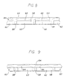
- FIGS. 8 and 9 each illustrates a different composite panel, the edge strips and the machinable veneers of the composite panel form being arranged in different configurations.
- the machinable veneer 64 is continuous, although it may be formed from several elements, and extends along the entire upper surface of the composite panels 50. Both the substrate and the end boards alternatively contact a lower surface of the machinable veneer.
- the lower surface of the machinable veneer only contacts the substrate, and the combined veneer/substrate alternates horizontally with the edge strips 58.
- FIG. 8 or 9 composite panel configuration is preferred depends upon the specifics of the assembling and forming the composite panel, and is a design choice.
- the broken lines in FIGS. 8 and 9 illustrate an example of the final cuts that are provided by the reengineered rip saw to form the engineered mouldings.
- This method begins with the fabrication of a receiving panel 200. shown in FIG. 10.
- This panel 200 includes a thin veneer layer or sheet 202, which may be made of wood. This is not a "veneer” in the sense of prior art veneer mouldings. It is flat and planar and is not bent to conform to the shape of any other piece.
- a series of substrates 204 are adhered linearly to the veneer layer 202 so that the substrates, each of which is of rectangular cross section, is parallel, defining plows or troughs 206 between the substrates, the plows also being of rectangular cross section.
- the receiving panel 200 thus has an open surface on which the plows 206 are exposed (the top surface shown in FIG. 10) and an opposing surface on which the plows are not accessible.
- the width of the substrate 204 is greater than that of the plows 206.
- a composite panel 206 shown in FIG. 11, is formed by inserting edge strips 210. preferably made of wood, in the plows 206 between the substrates 204, to form a panel corresponding to the panels 50 of FIG. 1.
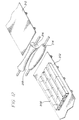
- the receiving panel 200 is placed on a flexible conveyor belt 212 which passes between a pair of opposing rollers 214 and 216.
- One roller 214 is wider in the middle and narrower at the ends. whereas the other roller 216 is narrower in the middle and wider at the ends.
- the rollers 214 and 216 are thus configured so as to define between them an arcuate opening 218 through which the belt 212 and receiving panel 200 pass. It should be noted that when the rollers 214 and 216 are rotated, there are differences in the linear speeds of the opposing surfaces of the rollers due to their curvature. For this reason it is necessary for the rollers 214 and 216 and the belt 212 to be of material having a relatively low coefficient of friction and permitting slippage.
- the receiving panel 200 passes between the rollers 214 and 216, it is forced to assume a bowed configuration, as shown in FIG. 13, corresponding to the profile of the opening between the rollers 214 and 216.
- the open surface 220 of the receiving panel 200 on which plows 206 are exposed is then in tension, whereas the opposite surface 222, which is the surface of the veneer layer 202 on which the plows 206 are not accessible, is in compression.
- each plow 206 With the receiving panel 200 in its bowed configuration, each plow 206 is forced to assume an open configuration in which it is wider at its open end than it is at its closed end, approximating a trapezoid. This configuration makes it much easier to insert the edge strips 210.
- adhesive Prior to inserting the edge strips 210, adhesive is applied to the surfaces of the plows 206 that will be in contact with the edge strips. Once the edge strips 210 are in place, the composite panel 108 thus formed is cause to assume its relaxed, unbowed configuration, as shown in FIG. 11. This can, in most cases, be accomplished by simply releasing the composite panel 208 from the constraining forces that have caused it to assume its bowed configuration.
- an adhesive is applied to the interface between the strips and the surfaces of the plows 206, particularly the surfaces of the substrates 204 that abut the surfaces of the strips 210.
- the adhesives can be applied either to the receiving panel 200 or to the strips 210. The insertion of the strips 210 in the bowed, open plows facilitates an even application of the adhesive.
- a second veneer layer 224 on the side opposite the first veneer layer 202, as shown in FIG. 14, after the edge strips 210 have been inserted.
- the engineered moulding to be manufactured is to have a structure that does not require the first veneer layer 202, that layer can be formed of paper, plastic, or another disposable material, instead of wood (preferably about 1/16" thick), and can be removed by a machining, milling, grinding, abrading or sanding step after the edge strips 204 have been installed.
- the moulding that is ultimately to be formed will include a wood veneer, or other veneer layer that is not structurally capable of holding the substrate 204 and not breaking during the bowing step described above, it may be desirable to use a paper veneer layer or a pealable plastic layer 202, which is then removed by sanding or pealing away and replaced by a wood veneer layer, applied to either side of the composite panel.
- a receiving panel 205 can be formed from a single piece of wood 226, as shown in FIG. 15.
- the plows 206 are then formed by removing material from one major surface of the panel 200,
- the plows 206 can advantageously be formed as saw kerfs by a reengineered rip saw of the design described above, or can be formed by conventional wood working methods.
- the resulting veneer layer 228 is not a separate piece, but is the integral part of the single wood piece 226 that extends along the closed side 230 of the panel beneath the plows 206. If it is desired to remove the integrally formed wood veneer layer 228 after the edge strips 210 have been inserted, this removal is preferably accomplished by planing.
- the composite panel is then cut lengthwise into parallel sections, by cutting through the edge strips 210. To do so, it is again advantageous to use the engineered rip saw. as explained above.
- Each linear section thus formed constitutes a separate engineered moulding. Additional shaping and profiling may be accomplished at the same time.
- the preferred material for the substrates 204 is a composite material, most preferably, particle board, medium density fiberboard or oriented strand board, but other materials may be used as explained above.
- each edge strip can consist of two co-extensive abutting laminations 210A and 210B.
- These laminations 210A and 210B are adhered to the adjacent surfaces of the plows 206, but are freely separable and have no adhesive applied along the surfaces on which they abut each other, which are perpendicular to the major surfaces 220 and 222 of the panel, as shown in FIG. 16.
- the veneer layer 202 is then cut along the lines indicated by the arrows A so that each of the laminations 210A and 210B form an outer surfaces of engineered mouldings, which do not require any additional finishing.
- the laminations 210A and 210B may, for example, be a decorative plastic laminate that forms the finished edge of the moulding and the veneer layer 202 may also be a plastic or thermal fused Melamine laminate, such as Formica.
- edge strips 210 can be made to close tolerances with respect to the plows 206, but still can be easily inserted. Moreover, damage to the work pieces during insertion of the edge strips 210 is avoided and adherence is facilitated by the tight fit obtained.
Landscapes
- Engineering & Computer Science (AREA)
- Life Sciences & Earth Sciences (AREA)
- Manufacturing & Machinery (AREA)
- Wood Science & Technology (AREA)
- Forests & Forestry (AREA)
- Veneer Processing And Manufacture Of Plywood (AREA)
- Laminated Bodies (AREA)
- Casting Or Compression Moulding Of Plastics Or The Like (AREA)
- Moulding By Coating Moulds (AREA)
- Panels For Use In Building Construction (AREA)
Claims (25)
- Verfahren zur Bildung einer Vielzahl gleichartiger Verbundformteile (56), von denen jedes eine größere Beständigkeit gegen Verziehen und Spalten besitzt als vergleichsweise ein gleichförmiges Stück aus massivem Holz gleicher Größe und Form, wobei das Verfahren die folgenden Schritte umfaßt:Bereitstellen einer Vielzahl an gleichartigen länglichen, sich axial erstreckenden Leisten (58; 210) mit rechteckigem Querschnitt, einer Vielzahl an gleichartigen länglichen, sich axial erstreckenden Substraten (62; 204) mit rechteckigem Querschnitt und mindestens eines maschinell bearbeitbaren Furniers (64; 202);Anordnen der Leisten (58; 210) parallel zueinander zwischen den Substraten (62; 204), wodurch somit ein Muster aus sich abwechselnden Leisten und Substraten gebildet wird, Kleben der Leisten (58; 210) an die angrenzenden Substrate (62; 204) und Anordnen und Kleben des Furniers (64; 202), so daß die Leisten (58; 210) und die Substrate (62; 204) unter Bildung einer Verbundplatte (50; 208) überlagert werden; undDurchschneiden der auf diese Weise gebildeten Verbundplatte (50; 208) an einer Vielzahl von Stellen (54), um so die Leisten (58; 210) in Längsrichtung zu schneiden, wobei eine Vielzahl an gleichartigen Verbundformteilen (56) gebildet werden, wobei jedes dieser Formteile (56) mindestens einen Abschnitt eines Substrats (62; 204), mindestens einen Abschnitt von mindestens zwei angrenzenden Leisten (58; 210) und einen verbundenen Abschnitt des maschinell bearbeitbaren Furniers (64; 202) umfaßt.
- Verfahren nach Anspruch 1, wobei die Verbundplatte (50; 208) durch die Leiste (58; 210) geschnitten wird, indem sie durch eine Blattspaltsäge (80) geführt wird, welche eine Vielzahl an parallelen Schneiden (130) besitzt.
- Verfahren nach Anspruch 2, wobei das Verbundmaterial eine Spanplatte, mitteldichte Faserplatte, Oriented Strand Board (Platte mit orientiert gestreuten Furnierstreifen), Furnierschichtholz, Sperrholz, Zementplatte oder Hartplastschaum ist.
- Verfahren nach Anspruch 1, wobei die Leisten (58; 210) aus Holz hergestellt sind and der Rest der Platte (59; 208) zumindest teilweise aus einem Verbundmaterial hergestellt ist.
- Verfahren nach Anspruch 4, wobei das Verbundmaterial eine Spanplatte, mitteldichte Faserplatte, Oriented Strand Board (Platte mit orientiert gestreuten Furnierstreifen), Furnierschichtholz, Sperrholz, Zementplatte oder Hartplastschaum ist.
- Verfahren nach Anspruch 1, wobei jede Leiste (210) durch zwei ängrenzende Laminierungen (210a and 210b) gebildet wird, die nicht miteinander verklebt sind.
- Verfahren nach Anspruch 1, wobei:die Substrate (204) mit dem Furnier (202) verklebt sind, um dadurch eine Aufnahmeplatte zu bilden, welche zwischen den Substraten (204) Nuten definiert;die Aufnahmeplatte (200) gebogen wird, um einen Bogen um eine Achse parallel zu den Nuten zu bilden, um so die Öffnungsfläche, entlang welcher die Nuten freiliegen, and eine Gegenfläche, von welcher die Nuten nicht zugänglich sind, zu vergrößern;aus Holz hergestellte Leisten (210) in die Nuten eingefügt werden, während die Aufnahmeplatte (200) gebogen ist, and ein Klebstoff auf eine Grenzfläche zwischen den Leisten (210) and den Oberflächen, welche die Nuten definieren, angewendet wird, unddie Aufnahmeplatte (200) zu einem nichtgebogenen Zustand rückgeführt wird and dadurch die Leisten (210) innerhalb der Nuten gesichert werden, wodurch somit eine Verbundplatte (208) gebildet wird.
- Verfahren nach Anspruch 7, welches ferner vor einem Schneiden der Verbundplatte (208) den Schritt des Hinzufügens einer aus Holz hergestellten zweiten Furnierschicht (224) zu der Öffnungsfläche der Aufnahmeplatte (200) and den Leisten (210) umfaßt.
- Verfahren nach Anspruch 8, welches ferner den Schritt des Entfernens von einem (202) der Furniere (64; 202) umfaßt.
- Verfahren nach Anspruch 9, wobei das eine Furnier (202) Papier ist.
- Verfahren nach Anspruch 9, wobei das Entfernen des Furniers (202) durch Schleifen erreicht wird.
- Verfahren nach Anspruch 7, wobei das Verbundmaterial eine Spanplatte, mitteldichte Faserplatte, Oriented Strand Board (Platte mit orientiert gestreuten Furnierstreifen), Furnierschichtholz, Sperrholz, Zementplatte oder Hartplastschaum ist.
- Verfahren nach Anspruch 7, wobei die Verbundplatte (208) durch die Leisten (210) geschnitten wird, indem sie durch eine Blattspaltsäge (80) geführt wind, welche eine Vielzahl an parallelen Schneiden (74) besitzt.
- Verfahren nach Anspruch 7, wobei die Aufnahmeplatte (200) gebogen wird, indem sie zwischen zwei Walzen (214 and 216) geführt wind, die so ausgestaltet sind, daß sie zwischen sich den Bogen definieren.
- Verbundplattenform, welche durch Sägen in eine Vielzahl an Verbundplanken zur Verwendung bei der Herstellung von linearen Elementen wie Formteilen unterteilt werden kann, umfassend:eine Vielzahl an sich axial erstreckenden Leisten (58; 210);eine Vielzahl an sich axial erstreckenden Substraten (62; 204), welche seitlich aus einem Material gebildet sind, welches verschieden ist von dem der Leisten, welche dazwischen mit den Leisten vorgesehen sind and an die Leisten geklebt sind, um so ein sich wiederholendes Muster aus Leisten (58; 210), welche durch Substrate (62; 204) getrennt sind, zu bilden; undein planares maschinell bearbeitbares Holzfurnier (64; 202), welches die Leisten (58; 210) und Substrate (62; 204) überlagert and damit verbunden ist.
- Verbundplattenform nach Anspruch 15, wobei die Substrate eine Spanplatte umfassen.
- Verbundplattenform nach Anspruch 15, wobei die Substrate eine mitteldichte Faserplatte umfassen.
- Verbundplattenform nach Anspruch 15, wobei die Substrate ein Oriented Strand Board (Platte mit orientiert gestreuten Furnierstreifen) umfassen.
- Verbundplattenform nach Anspruch 15, wobei die Substrate eine Verbundplatte aus Holzfurnier umfassen.
- Verbundplattenform nach Anspruch 15, wobei die Substrate einen Holzkern umfassen.
- Verbundplattenform nach Anspruch 15, wobei die Substrate eine Faserplatte umfassen.
- Verbundplattenform nach Anspruch 15, wobei die Substrate eine Hartfaserplatte umfassen.
- Verbundplattenform nach Anspruch 15, wobei das maschinell bearbeitbare Furnier (64; 202) auch die Leisten (58; 210) überlagert.
- Verbundplattenform nach Anspruch 15, wobei das maschinell bearbeitbare Furnier eine Vielzahl an planaren maschinell bearbeitbaren Furnieren (64) umfaßt, wobei jedes der Vielzahl an maschinell bearbeitbaren Furnieren zwischen den Leisten (58) angeordnet ist.
- Verbundplattenform nach Anspruch 15, wobei die Substrate (62; 204) and das Furnier (202) einen Kanal (206) ausbilden, in welchen eine der Leisten (210) hineinpaßt.
Applications Claiming Priority (3)
| Application Number | Priority Date | Filing Date | Title |
|---|---|---|---|
| US818764 | 1997-03-14 | ||
| US08/818,764 US5944928A (en) | 1996-09-18 | 1997-03-14 | Method for making composite panels and engineered mouldings |
| PCT/US1998/004788 WO1998041371A1 (en) | 1997-03-14 | 1998-03-12 | Method for making composite panels and engineered mouldings |
Publications (2)
| Publication Number | Publication Date |
|---|---|
| EP0966342A1 EP0966342A1 (de) | 1999-12-29 |
| EP0966342B1 true EP0966342B1 (de) | 2002-05-29 |
Family
ID=25226344
Family Applications (1)
| Application Number | Title | Priority Date | Filing Date |
|---|---|---|---|
| EP98910319A Expired - Lifetime EP0966342B1 (de) | 1997-03-14 | 1998-03-12 | Verfahren zur herstellung von verbundplatten und formkörpern aus schichtholzbauteilen |
Country Status (7)
| Country | Link |
|---|---|
| US (1) | US5944928A (de) |
| EP (1) | EP0966342B1 (de) |
| AT (1) | ATE218088T1 (de) |
| AU (1) | AU6458598A (de) |
| CA (1) | CA2283988A1 (de) |
| DE (1) | DE69805611T2 (de) |
| WO (1) | WO1998041371A1 (de) |
Families Citing this family (25)
| Publication number | Priority date | Publication date | Assignee | Title |
|---|---|---|---|---|
| US6143119A (en) * | 1997-04-09 | 2000-11-07 | Seidner; Marc A. | Composite moulding and method of making |
| WO2001012402A1 (en) * | 1999-08-13 | 2001-02-22 | Seidner Marc A | Method of making engineered mouldings |
| US6701984B2 (en) | 1999-12-15 | 2004-03-09 | 9069-0470 Quebec Inc. | Wood board made of a plurality of wood pieces, method of manufacture and apparatus |
| US6519912B1 (en) | 2000-04-11 | 2003-02-18 | Temple-Inland Forest Products Corporation | Composite wood products |
| US6682680B2 (en) | 2001-11-10 | 2004-01-27 | Joined Products, Inc. | Method of applying an edge sealing strip to a wood product piece |
| US20040163571A1 (en) * | 2003-01-30 | 2004-08-26 | Dorset Firedoor Systems, Inc. | Fire door core assembly |
| ES1054725Y (es) * | 2003-05-14 | 2003-12-01 | Barberan Latorre Jesus Frco | Dispositivo para la aplicacion de un producto de relleno sobre superficies porosas de paneles o perfiles de madera |
| US20060078666A1 (en) * | 2004-10-08 | 2006-04-13 | Smith Daniel G | Laminated coconut palm and products thereof |
| US9485917B2 (en) * | 2006-12-15 | 2016-11-08 | Ecovative Design, LLC | Method for producing grown materials and products made thereby |
| US8480835B2 (en) | 2010-09-03 | 2013-07-09 | The Diller Corporation | Apparatus and method to manufacture shaped counter top edges for custom counter tops |
| US8479590B2 (en) * | 2010-11-18 | 2013-07-09 | Honeywell International Inc. | System for monitoring structural assets |
| US9782911B1 (en) | 2013-06-19 | 2017-10-10 | Gtk, Llc | Systems, methods and apparatus for the production of finger jointed dimensioned lumber, poles, beams and molding stock from green rough trim blocks |
| US11277979B2 (en) | 2013-07-31 | 2022-03-22 | Ecovative Design Llc | Mycological biopolymers grown in void space tooling |
| US20150101509A1 (en) | 2013-10-14 | 2015-04-16 | Gavin R. McIntyre | Method of Manufacturing a Stiff Engineered Composite |
| GB2536247B (en) * | 2015-03-10 | 2021-04-07 | P T Kayu Permata | A door component and a method for manufacturing the same |
| WO2016168563A1 (en) | 2015-04-15 | 2016-10-20 | Ecovative Design Llc | Process for production of mycelial composite surfaces in a roll-to-roll format |
| CN204754097U (zh) * | 2015-06-25 | 2015-11-11 | 深圳市寰为木业有限公司 | 一种双框式基板实木复合地板 |
| HUE054917T2 (hu) | 2016-03-01 | 2021-10-28 | The Fynder Group Inc | Gombafonalas bioszõnyegek, ezek elõállítási módszerei és felhasználási módjai |
| US11359074B2 (en) | 2017-03-31 | 2022-06-14 | Ecovative Design Llc | Solution based post-processing methods for mycological biopolymer material and mycological product made thereby |
| US11266085B2 (en) | 2017-11-14 | 2022-03-08 | Ecovative Design Llc | Increased homogeneity of mycological biopolymer grown into void space |
| US11920126B2 (en) | 2018-03-28 | 2024-03-05 | Ecovative Design Llc | Bio-manufacturing process |
| US11293005B2 (en) | 2018-05-07 | 2022-04-05 | Ecovative Design Llc | Process for making mineralized mycelium scaffolding and product made thereby |
| US11343979B2 (en) | 2018-05-24 | 2022-05-31 | Ecovative Design Llc | Process and apparatus for producing mycelium biomaterial |
| CA3113935A1 (en) | 2018-10-02 | 2020-04-09 | Ecovative Design Llc | A bioreactor paradigm for the production of secondary extra-particle hyphal matrices |
| AU2022270087A1 (en) | 2021-05-04 | 2023-12-07 | Ecovative Design Llc | Aerial mycelia and methods of making the same |
Family Cites Families (11)
| Publication number | Priority date | Publication date | Assignee | Title |
|---|---|---|---|---|
| DE175877C (de) * | ||||
| FR605065A (fr) * | 1925-10-27 | 1926-05-19 | Marly Freres Soc | Procédé de fabrication de moulures en bois pour cadres de toutes sortes |
| GB607213A (en) * | 1945-08-17 | 1948-08-26 | Bruno Jablonsky | Improvements in and relating to material comprising bonded wood laminae |
| FR1295269A (fr) * | 1961-07-19 | 1962-06-01 | Menuiseries en bois indéformables et procédé pour leur fabrication | |
| US3477485A (en) * | 1967-05-19 | 1969-11-11 | Potlatch Forests Inc | Method for assembling wooden t and i beams |
| US4111247A (en) * | 1977-01-13 | 1978-09-05 | Weyerhaeuser Company | Log cutting and rejoining process for lumber manufacture |
| FR2561161B1 (fr) * | 1984-03-14 | 1990-05-11 | Rosa Sa Fermeture | Procede de fabrication de lames rainurees ou moulurees telles que lames de volets, moulures de menuiserie ou de batiment et dispositif pour la mise en oeuvre de ce procede |
| US4687529A (en) * | 1985-08-30 | 1987-08-18 | Miles Laboratories, Inc. | Method of making a reagent test device containing hydrophobic barriers |
| FR2624781B1 (fr) * | 1987-12-22 | 1992-08-28 | Mathis Sa Ets Paul | Procede de fabrication d'elements profiles en bois, dispositif pour la mise en oeuvre de ce procede et elements profiles ainsi obtenus |
| DE4204675A1 (de) * | 1992-02-17 | 1993-08-19 | Valentin Schollmayer | Holzprofil, insbesondere zu bearbeitendes rohprofil aus holz fuer fensterrahmen |
| ES2049657B1 (es) * | 1992-10-08 | 1994-11-01 | Sanz Agustin Sansano | Panel de madera moldurada para recubrimientos decorativos. |
-
1997
- 1997-03-14 US US08/818,764 patent/US5944928A/en not_active Expired - Lifetime
-
1998
- 1998-03-12 CA CA002283988A patent/CA2283988A1/en not_active Abandoned
- 1998-03-12 EP EP98910319A patent/EP0966342B1/de not_active Expired - Lifetime
- 1998-03-12 DE DE69805611T patent/DE69805611T2/de not_active Expired - Fee Related
- 1998-03-12 AT AT98910319T patent/ATE218088T1/de active
- 1998-03-12 WO PCT/US1998/004788 patent/WO1998041371A1/en not_active Ceased
- 1998-03-12 AU AU64585/98A patent/AU6458598A/en not_active Abandoned
Also Published As
| Publication number | Publication date |
|---|---|
| AU6458598A (en) | 1998-10-12 |
| WO1998041371A1 (en) | 1998-09-24 |
| US5944928A (en) | 1999-08-31 |
| DE69805611D1 (de) | 2002-07-04 |
| EP0966342A1 (de) | 1999-12-29 |
| ATE218088T1 (de) | 2002-06-15 |
| DE69805611T2 (de) | 2003-02-06 |
| CA2283988A1 (en) | 1998-09-24 |
Similar Documents
| Publication | Publication Date | Title |
|---|---|---|
| US6203653B1 (en) | Method of making engineered mouldings | |
| EP0966342B1 (de) | Verfahren zur herstellung von verbundplatten und formkörpern aus schichtholzbauteilen | |
| EP0727292B1 (de) | verfahren zur herstellung von hartholzbodenstreifen | |
| US6148884A (en) | Low profile hardwood flooring strip and method of manufacture | |
| US5113632A (en) | Solid wood paneling system | |
| CA3053601C (en) | A method for dividing a board into a first panel and a second panel, a method of forming a mechanical locking system for locking of a first and a second panel, and building panels | |
| KR20070107720A (ko) | 합판 제조 방법 | |
| WO1992012007A1 (en) | A process for re-manufacturing wood boards and the product produced thereby | |
| US20020132050A1 (en) | Apparatus and methods for producing artificially distressed plank flooring | |
| CN101879737A (zh) | 竹重组材家具制造方法 | |
| US20110252725A1 (en) | Structure and method for installing staircase treads | |
| US5826396A (en) | Double-sided, single pass grooving of countertops and other building structures | |
| CA2636544C (en) | Floor planks production machine and method | |
| US5817202A (en) | Composite moulding and method of making | |
| FI84646B (fi) | Foerfarande foer framstaellning av en spegeldoerr och spegeldoerr. | |
| US20090071095A1 (en) | Methods and Systems for Manufacture of a Rot-Resistant Shutter | |
| US5735326A (en) | Split jamb for a door frame opening and method of making a split jamb | |
| US3216875A (en) | Method of making structural materials | |
| US4133361A (en) | Method for machining joints for miters, grooves and other joinery in a beveled or straight panel edge and apparatus for same | |
| CN114290446B (zh) | 一种饰面刨花板防崩边高效铣削加工方法 | |
| WO2001012402A1 (en) | Method of making engineered mouldings | |
| CA2043130A1 (en) | Process and a machine for producing a component in board form having a postforming edge, as well as a board produced by this process | |
| AU593272B2 (en) | Timber planing machine | |
| AU2008222014A1 (en) | Laminated Weatherboard | |
| US6499269B1 (en) | Method of making a window ledge |
Legal Events
| Date | Code | Title | Description |
|---|---|---|---|
| PUAI | Public reference made under article 153(3) epc to a published international application that has entered the european phase |
Free format text: ORIGINAL CODE: 0009012 |
|
| 17P | Request for examination filed |
Effective date: 19990922 |
|
| AK | Designated contracting states |
Kind code of ref document: A1 Designated state(s): AT CH DE ES FR GB IT LI SE |
|
| GRAG | Despatch of communication of intention to grant |
Free format text: ORIGINAL CODE: EPIDOS AGRA |
|
| 17Q | First examination report despatched |
Effective date: 20010405 |
|
| GRAG | Despatch of communication of intention to grant |
Free format text: ORIGINAL CODE: EPIDOS AGRA |
|
| GRAH | Despatch of communication of intention to grant a patent |
Free format text: ORIGINAL CODE: EPIDOS IGRA |
|
| GRAH | Despatch of communication of intention to grant a patent |
Free format text: ORIGINAL CODE: EPIDOS IGRA |
|
| GRAA | (expected) grant |
Free format text: ORIGINAL CODE: 0009210 |
|
| AK | Designated contracting states |
Kind code of ref document: B1 Designated state(s): AT CH DE ES FR GB IT LI SE |
|
| PG25 | Lapsed in a contracting state [announced via postgrant information from national office to epo] |
Ref country code: FR Free format text: LAPSE BECAUSE OF FAILURE TO SUBMIT A TRANSLATION OF THE DESCRIPTION OR TO PAY THE FEE WITHIN THE PRESCRIBED TIME-LIMIT Effective date: 20020529 Ref country code: AT Free format text: LAPSE BECAUSE OF FAILURE TO SUBMIT A TRANSLATION OF THE DESCRIPTION OR TO PAY THE FEE WITHIN THE PRESCRIBED TIME-LIMIT Effective date: 20020529 |
|
| REF | Corresponds to: |
Ref document number: 218088 Country of ref document: AT Date of ref document: 20020615 Kind code of ref document: T |
|
| REG | Reference to a national code |
Ref country code: GB Ref legal event code: FG4D |
|
| REG | Reference to a national code |
Ref country code: CH Ref legal event code: EP |
|
| REF | Corresponds to: |
Ref document number: 69805611 Country of ref document: DE Date of ref document: 20020704 |
|
| PG25 | Lapsed in a contracting state [announced via postgrant information from national office to epo] |
Ref country code: SE Free format text: LAPSE BECAUSE OF FAILURE TO SUBMIT A TRANSLATION OF THE DESCRIPTION OR TO PAY THE FEE WITHIN THE PRESCRIBED TIME-LIMIT Effective date: 20020829 |
|
| PG25 | Lapsed in a contracting state [announced via postgrant information from national office to epo] |
Ref country code: ES Free format text: LAPSE BECAUSE OF FAILURE TO SUBMIT A TRANSLATION OF THE DESCRIPTION OR TO PAY THE FEE WITHIN THE PRESCRIBED TIME-LIMIT Effective date: 20021128 |
|
| EN | Fr: translation not filed | ||
| REG | Reference to a national code |
Ref country code: CH Ref legal event code: NV Representative=s name: ISLER & PEDRAZZINI AG |
|
| PLBE | No opposition filed within time limit |
Free format text: ORIGINAL CODE: 0009261 |
|
| STAA | Information on the status of an ep patent application or granted ep patent |
Free format text: STATUS: NO OPPOSITION FILED WITHIN TIME LIMIT |
|
| 26N | No opposition filed |
Effective date: 20030303 |
|
| REG | Reference to a national code |
Ref country code: CH Ref legal event code: PCAR Free format text: ISLER & PEDRAZZINI AG;POSTFACH 1772;8027 ZUERICH (CH) |
|
| PGFP | Annual fee paid to national office [announced via postgrant information from national office to epo] |
Ref country code: CH Payment date: 20080228 Year of fee payment: 11 |
|
| PGFP | Annual fee paid to national office [announced via postgrant information from national office to epo] |
Ref country code: DE Payment date: 20080306 Year of fee payment: 11 |
|
| PGFP | Annual fee paid to national office [announced via postgrant information from national office to epo] |
Ref country code: IT Payment date: 20080328 Year of fee payment: 11 |
|
| REG | Reference to a national code |
Ref country code: CH Ref legal event code: PL |
|
| PGFP | Annual fee paid to national office [announced via postgrant information from national office to epo] |
Ref country code: GB Payment date: 20090714 Year of fee payment: 12 |
|
| PG25 | Lapsed in a contracting state [announced via postgrant information from national office to epo] |
Ref country code: LI Free format text: LAPSE BECAUSE OF NON-PAYMENT OF DUE FEES Effective date: 20090331 Ref country code: DE Free format text: LAPSE BECAUSE OF NON-PAYMENT OF DUE FEES Effective date: 20091001 Ref country code: CH Free format text: LAPSE BECAUSE OF NON-PAYMENT OF DUE FEES Effective date: 20090331 |
|
| GBPC | Gb: european patent ceased through non-payment of renewal fee |
Effective date: 20100312 |
|
| PG25 | Lapsed in a contracting state [announced via postgrant information from national office to epo] |
Ref country code: GB Free format text: LAPSE BECAUSE OF NON-PAYMENT OF DUE FEES Effective date: 20100312 Ref country code: IT Free format text: LAPSE BECAUSE OF NON-PAYMENT OF DUE FEES Effective date: 20090312 |