EP0966353B1 - Verfahren und einrichtung zur gravur von druckzylindern - Google Patents
Verfahren und einrichtung zur gravur von druckzylindern Download PDFInfo
- Publication number
- EP0966353B1 EP0966353B1 EP98912253A EP98912253A EP0966353B1 EP 0966353 B1 EP0966353 B1 EP 0966353B1 EP 98912253 A EP98912253 A EP 98912253A EP 98912253 A EP98912253 A EP 98912253A EP 0966353 B1 EP0966353 B1 EP 0966353B1
- Authority
- EP
- European Patent Office
- Prior art keywords
- engraving
- printing cylinder
- engraved
- printing
- cylinders
- Prior art date
- Legal status (The legal status is an assumption and is not a legal conclusion. Google has not performed a legal analysis and makes no representation as to the accuracy of the status listed.)
- Expired - Lifetime
Links
Images
Classifications
-
- H—ELECTRICITY
- H04—ELECTRIC COMMUNICATION TECHNIQUE
- H04N—PICTORIAL COMMUNICATION, e.g. TELEVISION
- H04N1/00—Scanning, transmission or reproduction of documents or the like, e.g. facsimile transmission; Details thereof
- H04N1/387—Composing, repositioning or otherwise geometrically modifying originals
- H04N1/3872—Repositioning or masking
- H04N1/3873—Repositioning or masking defined only by a limited number of coordinate points or parameters, e.g. corners, centre; for trimming
- H04N1/3875—Repositioning or masking defined only by a limited number of coordinate points or parameters, e.g. corners, centre; for trimming combined with enlarging or reducing
-
- B—PERFORMING OPERATIONS; TRANSPORTING
- B41—PRINTING; LINING MACHINES; TYPEWRITERS; STAMPS
- B41C—PROCESSES FOR THE MANUFACTURE OR REPRODUCTION OF PRINTING SURFACES
- B41C1/00—Forme preparation
- B41C1/02—Engraving; Heads therefor
- B41C1/04—Engraving; Heads therefor using heads controlled by an electric information signal
Definitions
- the invention relates to the field of electronic reproduction technology and relates to a method for engraving screened printing cylinders, in particular for gravure printing, by means of an engraving device in an electronic Engraving machine.
- an engraving element moves, which, for example, is an engraving stylus Has cutting tool, in the axial direction continuously or step by step along a rotating pressure cylinder.
- the one controlled by an engraving signal Engraving stylus cuts a series of recesses arranged in a grid, hereinafter called the well, in the outer surface of the printing cylinder.
- the Engraving signal is made from the superposition of one of the tonal values between "black” and image signal representing "white” with a periodic raster signal educated.
- the grid signal determines together with the peripheral speed of the impression cylinder and the axial feed speed of the engraving member the geometry of the engraved grid.
- the periodic raster signal one vibrating stroke movement of the engraving stylus controls the image signal accordingly the tones to be reproduced the depths of the in the surface engraved cell of the impression cylinder.
- Such an engraving machine for engraving printing cylinders is, for example known from WO-A-94/19900. It is about a calibration procedure of the engraving signal, in which wells are engraved, the actual geometric dimensions of the engraved cells and the one from the comparison the measured actual dimensions with specified nominal dimensions are determined with which the engraving signal values for selected Tone values are corrected in such a way that those engraved in the form of the wells are actually engraved Actual tone values correspond to the target tone values defined by the image signal values.
- GB-A-1407487 is another engraving machine for engraving printing cylinders known. It is about a process for engraving one out of several existing image and text parts composed according to a layout plan Print page, in which the engraving data required to engrave the print page before Engraving from the engraving data of the individual image and text parts according to the layout plan are compiled and saved into overall engraving lines and at which the compiled engraving data of the total engraving lines during the engraving read out and fed to the engraving element.
- sequential i.e. sequential engravings with the same or different Engraving parameters such as the screen parameters screen angle and raster width are generated.
- Examples of sequential engravings are the post-engraving of areas within a first engraving or multiple engravings (Use) of halftone images and line information or barcodes in the axial direction. These sequential engravings can be on a printing cylinder or on several printing cylinders with the same or different diameters.
- the object of the present invention is therefore to provide a method for engraving screened Printing cylinders for gravure printing, using an engraving device to improve in an electronic engraving machine such that engravings with the same or different engraving parameters on at least one Printing cylinders can be carried out automatically in one operation.
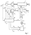
- FIG. 1 shows a basic block diagram of an engraving machine for engraving Impression cylinders.
- a printing cylinder (1) is driven in rotation by a rotary drive (2).
- An engraving member (4) mounted on an engraving carriage (3) moves with the help a spindle (6) driven by a feed drive (5) in the axial direction past the rotating pressure cylinder (1).
- the engraving element (4) is an electromagnetic engraving element in the exemplary embodiment and essentially has one by an electromagnetic drive system moving engraving stylus as a cutting tool, a sliding foot and one Scraper on.
- Engraving organ (4) cuts a series of engraving lines arranged in a grid Cups in the outer surface of the rotating pressure cylinder (1), while the engraving member (4) gradually axially along the printing cylinder (1) emotional.
- the sliding foot which is on the surface of the rotating during the engraving Pressure cylinder (1) supports, ensures a constant distance between the engraving stylus in its rest position and the outer surface.
- the one on the outer surface sliding scraper removes the one that forms when the cells are cut Material.
- the printing cylinder (1) is engraved in the illustrated embodiment on individual engraving lines running circularly around the impression cylinder (1), the engraving member (4) each having an engraving line axial feed step to the next engraving line.
- Such an engraving process is described for example in US 4,013,829 A.
- the engraving signal (G) on line (7) is produced in an engraving amplifier (8) the superposition of a periodic raster signal (R), also called vibration, with analog image values (B), which are the tonal values of the engraved Represent cells between "black” and "white".
- R periodic raster signal
- B analog image values
- the frequency of the raster signal (R) together with the peripheral speed of the printing cylinder (1) and the axial feed increment of the engraving member (4) determine the geometry of the screen to be engraved with respect to screen angle and screen ruling.
- the raster signal (R) is generated in a sequence control (9) and the engraving amplifier (8) fed via a line (10).
- the engraving data (GD) are engraving lines for in an engraving data memory (11) Engraving line in the order required to engrave the impression cylinder (1) stored in the form of files for the jobs to be processed in an engraving order.
- Each well to be engraved has an engraving date of at least one Byte assigned, which among other things as engraving information to be engraved Contains tonal value between "black” and "white”.
- the engraving data (GD) are, for example, by dot and line, optoelectronic Scanning of an original to be reproduced obtained in a scanner and then stored in the engraving data memory (11).
- the engraving data (GD) are read out of the engraving data memory (11) by means of a reading clock sequence T S and converted into the analog image values (B) in an A / D converter (13) Engraving amplifiers (8) are fed via a line (14).
- the reading cycle sequence T S is also generated in the sequence control (9) and reaches the engraving data memory (11) via a line (15).
- the sequence control (9) also generates a control command S 1 "Engraving release", which is fed to the engraving data memory (11) via a line (16) and in each case releases the engraving of the cells on the individual engraving lines.
- the sequence control (9) is synchronized with the rotary movement of the printing cylinder (1), by a pulse generator mechanically coupled to the rotary drive (2) (17) a synchronous signal via the line (18) to the sequence control (9) supplies.
- the sequence control (9) is used to carry out the automatic according to the invention sequential engraving with the same or different engraving parameters various control commands according to a programmable schedule generated for the jobs to be processed in a current engraving job.
- the engraving parameters can, for example, the grid parameters, the scale or the Gradation.
- the individual job data including the engraving parameters for the individual jobs of a current engraving order are saved in the sequence control (9) entered.
- the rotary drive (2) has a drive motor which can be varied in speed. After the printing cylinder (1), which has a large mass, has been introduced into the engraving machine, the speed of the drive motor is continuously increased from standstill until the printing cylinder (1) has reached its respective working speed. With a control command S 2 "speed change" on a line (19) to the rotary drive (2), the peripheral speed of the printing cylinder (1) can be varied by changing the speed according to the grids to be engraved when the printing cylinder (1) is rotating.
- the feed drive (5) is designed as a positioning drive with a stepper motor. Determines the frequency of a pulse clock sequence supplied to the stepper motor the speed of the stepper motor and thus the feed speed of the Engraving organ (4).
- each cycle of the pulse cycle sequence covers an increment of travel of the engraving member (4) corresponds to the respective axial position by counting the cycles the engraving member (4) can be determined.
- the corresponds to an axial target position of the engraving member (4) with the number of the Stepper motor supplied clocks of the pulse clock sequence according to the respective Axial actual position of the engraving system (4) can be an exact axial positioning of the engraving member (4).
- Accurate axial positioning of the engraving element (4) is when moving to starting positions and when carrying out the gradual feed movement from engraving line to engraving line during the Engraving required.
- a control command S 3 "Start / Stop" on a line (20) controls the feed movement of the engraving member (4) when approaching the axial starting positions before the engraving and the step-by-step feed movement during the engraving.
- Another control command S 4 "feed direction” on a line (21) defines the feed direction of the engraving member (4) when moving to the starting positions.
- Another control command S 5 "feed width” on a line (22) determines the respective feed step width or the distance between the engraving lines in accordance with the grid to be engraved.
- the axial start positions (SP), the axial end positions (EP) and the infeed position of the engraving member (4) during the engraving of the individual jobs are transmitted to the feed control (5) via a line (23).
- the engraving element (4) has an electrically controllable lifting device (not shown) on which the active part of the engraving member (4) with engraving stylus, Sliding foot and scraper for performing an engraving in a working position on the
- the surface of the rotating printing cylinder (1) is lowered and in the event of engraving interruptions and positioning of the engraving member (4) from the lateral surface of the Raises the pressure cylinder (1) to a rest position.
- Another not shown Actuating device controls the radial feed of the engraving member (4) in dependence of the respective diameter of the printing cylinder (1).
- Another control signal S 6 "lifting" and “infeed” on a line (24) from the sequence control (9) to the lifting device and the adjusting device of the engraving member (4) controls the radial feeding of the engraving member (4) and the lifting and lowering of the active part of the engraving member (4).
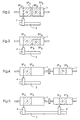
- FIG. 2 shows a first example of a sequential engraving of two jobs on one Printing cylinder (1).
- the barcode file of job "A” and the image file of job “B” are stored in the engraving data memory (11) in FIG. 1 as well as the different raster parameters, the starting positions (SP A ; SP B ) and the end positions (EP A ; EP B ) of the two jobs are entered in the sequence control (9).
- the required peripheral speed of the Printing cylinder (1) taking into account the respective cylinder diameter and the feed widths of the engraving member (4) are determined for the engraving of the different Grid must be set in the two jobs.
- FIG. 3 shows a second example of a sequential engraving of two jobs on one Printing cylinder (1).
- an initial engraving "A” and then a post-engraving should be carried out on the impression cylinder (1) B "into an area with one single left out at the initial engraving”
- a " Engraving element (4) can be engraved automatically in one operation.
- First engraving "A” and post-engraving "B” are intended to have different grids with respect to screen angles and have a grid.
- the engraving lines required for initial and post-engraving are, for example, by overlaying the engraving data (GD) from the two Jobs (A; B) built up.
- the start positions of the post-engraving "B” in Feed and circumferential direction can also be calculated, with the re-engraving "B” only the engraving data (GD) of job “B” can be read out by engraving line.
- Fig. 4 shows a third example of a sequential engraving from two jobs to two mechanically coupled printing cylinders (1; 1 '), the different May have diameters (twin operation).
- An engraving "A” should appear on the first impression cylinder (1) and on the second impression cylinder (1 ') an engraving "B” with a single engraving element (4) automatically in engraved in one operation. Engraving "A” and engraving "B” have again different grids.
- Figure 5 shows a fourth example of sequential engraving from two jobs to two mechanically coupled printing cylinders (1; 1 '), which in turn are different May have diameters (twin operation).
- An engraving "A” should appear on the first impression cylinder (1) and on the second impression cylinder (1 ') an engraving "B", each with an engraving element (4; 4'), which together on the engraving trolley are automatically engraved in one operation become.
- Engraving "A” and engraving "B” have different grids.
- the two can mechanically coupled pressure cylinders (1; 1 ') of course also the same Have diameters and the engravings are carried out with the same engraving parameters become.
Landscapes
- Engineering & Computer Science (AREA)
- Manufacturing & Machinery (AREA)
- Multimedia (AREA)
- Signal Processing (AREA)
- Manufacture Or Reproduction Of Printing Formes (AREA)
Description
- Fig. 1
- ein prinzipielles Blockschaltbild einer Graviermaschine für Druckzylinder,
- Fig. 2
- ein erstes Beispiel für eine sequentielle Gravur auf einem Druckzylinder,
- Fig. 3
- ein zweites Beispiel für eine sequentielle Gravur auf einem Druckzylinder,
- Fig. 4
- ein drittes Beispiel für eine sequentielle Gravur auf zwei Druckzylindern und
- Fig. 5
- ein viertes Beispiel für eine sequentielle Gravur auf zwei Druckzylindern.
Ein weiterer Steuerbefehl S4 "Vorschubrichtung" auf einer Leitung (21) legt die Vorschubrichtung des Gravierorgans (4) beim Anfahren der Startpositionen fest. Ein anderer Steuerbefehl S5 "Vorschubweite" auf einer Leitung (22) bestimmt entsprechend dem zu gravierenden Raster die jeweilige Vorschubschrittweite bzw. den Abstand zwischen den Gravierlinien. Über eine Leitung (23) werden die axialen Startpositionen (SP), die axialen Endpositionen (EP) sowie die Zustellposition des Gravierorgans (4) bei der Gravur der einzelnen Jobs an die Vorschubsteuerung (5) übermittelt.
Claims (12)
- Verfahren zur Gravur von gerasterten Druckzylindern für den Tiefdruck in einer elektronischen Graviermaschine, bei demin Abhängigkeit von vorgegebenen Gravurparametern ein Graviersignal zur Ansteuerung eines Gravierorgans (4) gewonnen wird,das Gravierorgan (4) in einen rotierenden Druckzylinder (1) Näpfchen graviert, die in einem durch vorgegebene Gravurparameter definierten Raster angeordnet sind und deren Graviertiefen die gravierten Tonwerte repräsentieren,das Gravierorgan (4) zur flächenhaften Gravur der Näpfchen eine axial zum Druckzylinders (1) verlaufende Vorschubbewegung an dem Druckzylinder (1) entlang ausführt, wobei die Geometrie des Rasters unter anderem durch die Umfangsgeschwindigkeit des rotierenden Druckzylinders (1) und durch die Vorschubgeschwindigkeit des Gravierorgans (4) bestimmt wird undUmfangsgeschwindigkeit und/oder Vorschubgeschwindigkeit in Abhängigkeit von den vorgegebenen Gravurparametern eingestellt werden, dadurch gekennzeichnet, daßin einem Arbeitsgang zeitlich nacheinander ablaufende Gravuren von Gravurjobs auf Gravurbereichen (A, B) mindestens eines Druckzylinders (1) mit mindestens einem Gravierorgan (4) mittels einer gemäß den Gravurjobs programmierbaren Ablaufsteuerung automatisch durchgeführt werden undin der Ablaufsteuerung in Abhängigkeit von jeweils vorgegebenen Gravurparametern der einzelnen Gravurjobs Steuersignale (S) erzeugt werden, welche entsprechend der Lage der einzelnen Gravurbereiche (A, B) auf dem oder den Druckzylindern (1) mindestens die axiale Position und die Vorschubgeschwindigkeit des Gravierorgans (4) sowie die Umfangsgeschwindigkeit des oder der Druckzylinder (1) nach Beendigung eines Gravurjobs für den darauffolgenden Gravurjob automatisch ändern.
- Verfahren nach Anspruch 1, dadurch gekennzeichnet, daß die Steuersignale (S) zusätzlich in Abhängigkeit von dem Durchmesser des oder der jeweils verwendeten Druckzylinder (1) erzeugt werden.
- Verfahren nach Anspruch 1 oder 2, dadurch gekennzeichnet, daß in der Ablaufsteuerung zusätzlich Steuersignale (S) erzeugt werden, welche die radiale Zustellung des Gravierorgans (4) zu dem oder den Druckzylindem (1), das Anlegen des Gravierorgans (4) an den oder die Druckzylinder (1) bei Gravurstart und das Abheben des Gravierorgans (4) bei Gravurende eines jeden Gravurjobs steuern.
- Verfahren nach einem der Ansprüche 1 bis 3, dadurch gekennzeichnet, daß die Gravurbereiche (A, B) mit unterschiedliche Raster graviert werden.
- Verfahren nach einem der Ansprüche 1 bis 4, dadurch gekennzeichnet, daß in den Gravurbereichen (A, B) Strichinformationen oder Halbtonbilder graviert werden.
- Verfahren nach einem der Ansprüche 1 bis 5, dadurch gekennzeichnet, daß die Gravurbereiche (A, B) mit einem Gravierorgan (4) auf einem Druckzylinder (1) in einem Arbeitsgang graviert werden.
- Verfahren nach einem der Ansprüche 1 bis 5, dadurch gekennzeichnet, daß die Gravurbereiche (A, B) mit einem Gravierorgan (4) auf mehreren Druckzylindern (1, 1') mit gleichen oder unterschiedlichen Durchmessern in einem Arbeitsgang graviert werden.
- Verfahren nach einem der Ansprüche 1 bis 7, dadurch gekennzeichnet, daß die Gravurbereiche (A, B) auf mehreren Druckzylindern (1; 1') mit gleichen oder unterschiedlichen Durchmessern mit jeweils einem dem betreffenden Druckzylinder (1; 1') zugeordneten Gravierorgan (4; 4') in einem Arbeitsgang graviert werden.
- Verfahren nach Anspruch 8, dadurch gekennzeichnet, daß die Gravierorgane (4; 4') auf einem axial verschiebbaren Gravierwagen (3) montiert sind.
- Verfahren nach einem der Ansprüche 7 bis 9, dadurch gekennzeichnet, daß die Druckzylinder (1; 1') mechanisch gekoppelt sind und gemeinsam rotatorisch angetrieben werden.
- Verfahren nach einem der Ansprüche 1 bis 10, dadurch gekennzeichnet, daß die Gravurbereiche (A, B) in axialer Richtung nebeneinander graviert werden.
- Verfahren nach einem der Ansprüche 1 bis 10, dadurch gekennzeichnet, daß in dem einen Gravurbereich (A, B) eine Erstgravur und in dem anderen Gravurbereich (A, B) eine Nachgravur in der Erstgravur durchgeführt wird.
Applications Claiming Priority (3)
| Application Number | Priority Date | Filing Date | Title |
|---|---|---|---|
| DE19710005 | 1997-03-12 | ||
| DE19710005A DE19710005A1 (de) | 1997-03-12 | 1997-03-12 | Verfahren und Einrichtung zur Gravur von Druckzylindern |
| PCT/DE1998/000460 WO1998040211A1 (de) | 1997-03-12 | 1998-02-17 | Verfahren und einrichtung zur gravur von druckzylindern |
Publications (2)
| Publication Number | Publication Date |
|---|---|
| EP0966353A1 EP0966353A1 (de) | 1999-12-29 |
| EP0966353B1 true EP0966353B1 (de) | 2001-12-19 |
Family
ID=7822979
Family Applications (1)
| Application Number | Title | Priority Date | Filing Date |
|---|---|---|---|
| EP98912253A Expired - Lifetime EP0966353B1 (de) | 1997-03-12 | 1998-02-17 | Verfahren und einrichtung zur gravur von druckzylindern |
Country Status (5)
| Country | Link |
|---|---|
| US (1) | US6302020B1 (de) |
| EP (1) | EP0966353B1 (de) |
| JP (1) | JP3199755B2 (de) |
| DE (2) | DE19710005A1 (de) |
| WO (1) | WO1998040211A1 (de) |
Families Citing this family (6)
| Publication number | Priority date | Publication date | Assignee | Title |
|---|---|---|---|---|
| US5947020A (en) * | 1997-12-05 | 1999-09-07 | Ohio Electronic Engravers, Inc. | System and method for engraving a plurality of engraved areas defining different screens |
| DE10012520A1 (de) * | 2000-03-15 | 2001-09-20 | Heidelberger Druckmasch Ag | Verfahren zur Herstellung von Druckzylindern |
| DE10045682A1 (de) * | 2000-09-15 | 2002-03-28 | Koenig & Bauer Ag | Einrichtung zum Bebildern von zylindrischen Oberflächen in Druckmaschinen |
| DE10052245B4 (de) * | 2000-10-21 | 2007-11-22 | Hell Gravure Systems Gmbh & Co. Kg | Verfahren und Vorrichtung zur Erstellung, insbesondere Gravur, von Näpfchen auf einem Druckformzylinder für den Tiefdruck |
| EP1568490B1 (de) * | 2004-02-27 | 2007-08-15 | HELL Gravure Systems GmbH & Co. KG | Verfahren zur direkten Gravur von Näpfchen zur Aufnahme von Druckfarbe für den Tiefdruck |
| DE102005045288A1 (de) * | 2005-09-22 | 2007-03-29 | Heidelberger Druckmaschinen Ag | Verfahren zur Steuerung eines Bebilderungsvorganges und Belichtungsgerät für die Bebilderung einer Druckform |
Family Cites Families (18)
| Publication number | Priority date | Publication date | Assignee | Title |
|---|---|---|---|---|
| DE2161038C3 (de) * | 1971-12-09 | 1985-06-20 | Dr.-Ing. Rudolf Hell Gmbh, 2300 Kiel | Verfahren zur Herstellung von gerasterten Druckformen |
| DE2413034C3 (de) | 1974-03-19 | 1983-11-17 | Dr.-Ing. Rudolf Hell Gmbh, 2300 Kiel | Verfahren und Anordnung zur Vermeidung von Fehlern bei der Reproduktion von Bildvorlagen |
| DE2513042C3 (de) * | 1975-03-25 | 1981-07-30 | Dr.-Ing. Rudolf Hell Gmbh, 2300 Kiel | Verfahren zum ortsgenauen Einstellen des Beginns und Endes der Reproduktion |
| GB2006567B (en) * | 1977-08-25 | 1982-08-25 | Dainippon Screen Mfg | Machine for and method of image production with variable reproduction scale |
| SE8202741L (sv) | 1981-05-11 | 1982-11-12 | Rca Corp | Kompatibelt, transkodningsbart och hierarkaliskt digitaltelevisionssystem |
| JPS57195249A (en) * | 1981-05-27 | 1982-11-30 | Dainippon Screen Mfg Co Ltd | Control method for scanning and recording of reproduced picture |
| DE3240654A1 (de) * | 1982-11-04 | 1984-05-10 | Dr.-Ing. Rudolf Hell Gmbh, 2300 Kiel | Verfahren zum ortsgeneuen nachgravieren von druckzylindern |
| JPS61285867A (ja) * | 1985-06-12 | 1986-12-16 | Dainippon Screen Mfg Co Ltd | 網点画像記録方法並びに装置 |
| DE4017164A1 (de) * | 1990-05-28 | 1991-12-05 | Rolf Hupka | Vorrichtung zur gleichzeitigen gravur und abtastung mehrerer gravurzylinder unterschiedlichen rasters mit einer gravur/abtastmaschine |
| US5186102A (en) * | 1990-10-11 | 1993-02-16 | Ricoh Company, Ltd. | Printer using a stencil |
| US5416597A (en) * | 1992-11-23 | 1995-05-16 | Mubaslat; Saed M. | System and technique for damping engraving head rings |
| US5424845A (en) * | 1993-02-25 | 1995-06-13 | Ohio Electronic Engravers, Inc. | Apparatus and method for engraving a gravure printing cylinder |
| US5522786A (en) * | 1994-03-28 | 1996-06-04 | Rexam Industries Corp. | Gravure roll |
| US5831745A (en) * | 1995-01-19 | 1998-11-03 | Dainippon Screen Mfg. Co., Ltd. | Gravure engraving system using two signals out of phase with each other for engraving a plurality of cells on a surface of a gravure cylinder |
| US5675420A (en) * | 1995-01-23 | 1997-10-07 | Ohio Electronic Engravers, Inc. | Intaglio engraving method and apparatus |
| US6025921A (en) * | 1995-01-23 | 2000-02-15 | Ohio Electronics Engravers, Inc. | Method and apparatus for engraving a mixed pattern |
| DE19627746C2 (de) * | 1995-07-14 | 2002-12-12 | Dainippon Screen Mfg | Tiefdruck-Graviersystem |
| US5947020A (en) * | 1997-12-05 | 1999-09-07 | Ohio Electronic Engravers, Inc. | System and method for engraving a plurality of engraved areas defining different screens |
-
1997
- 1997-03-12 DE DE19710005A patent/DE19710005A1/de not_active Withdrawn
-
1998
- 1998-02-17 EP EP98912253A patent/EP0966353B1/de not_active Expired - Lifetime
- 1998-02-17 US US09/380,851 patent/US6302020B1/en not_active Expired - Lifetime
- 1998-02-17 DE DE59802530T patent/DE59802530D1/de not_active Expired - Fee Related
- 1998-02-17 WO PCT/DE1998/000460 patent/WO1998040211A1/de not_active Ceased
- 1998-02-17 JP JP53905598A patent/JP3199755B2/ja not_active Expired - Fee Related
Also Published As
| Publication number | Publication date |
|---|---|
| WO1998040211A1 (de) | 1998-09-17 |
| EP0966353A1 (de) | 1999-12-29 |
| JP3199755B2 (ja) | 2001-08-20 |
| JP2000512930A (ja) | 2000-10-03 |
| DE19710005A1 (de) | 1998-09-17 |
| DE59802530D1 (de) | 2002-01-31 |
| US6302020B1 (en) | 2001-10-16 |
Similar Documents
| Publication | Publication Date | Title |
|---|---|---|
| EP0906193B1 (de) | Verfahren zur herstellung von prägeplatten | |
| DE69629279T2 (de) | Verfahren und vorrichtung zum gravieren | |
| DE69826709T2 (de) | System und verfahren zur gravur mehrerer gravuren mit unterschiedlichen gravurparametern | |
| EP0986465B1 (de) | Verfahren zur gravur von druckzylindern | |
| EP1001882B1 (de) | Verfahren zum positionieren von gravierorganen | |
| WO1989007525A1 (fr) | Procede et dispositif pour saisir des donnees de recouvrement de surfaces a imprimer | |
| EP1054769B1 (de) | Verfahren zur gravur von druckformen | |
| EP0966353B1 (de) | Verfahren und einrichtung zur gravur von druckzylindern | |
| EP0986466B1 (de) | Verfahren zur erzeugung und auswertung eines probeschnitts | |
| EP0925188B1 (de) | Verfahren und einrichtung zur steuerung eines gravierorgans | |
| DE10116672A1 (de) | Verfahren und Vorrichtung zur Materialbearbeitung | |
| EP0768795A1 (de) | Verfahren zur Herstellung einer Schablone, insbesondere für den Papier- oder Textildruck | |
| EP1386727B1 (de) | Verfahren zur Verbesserung der Qualität eines in einen Druckformzylinder gravierten Bildes | |
| EP2058122A1 (de) | Verfahren und Vorrichtung zur Gravur von Druckzylindern | |
| DE2219442A1 (de) | Bildübertragungsgerät, insbesondere Faksimileschreiber | |
| WO2000008842A1 (de) | Verfahren zur erzeugung und auswertung einer probegravur | |
| EP1069989B1 (de) | Verfahren zur gravur von druckformen | |
| DE19814939A1 (de) | Verfahren zum Positionieren von Gravierorganen | |
| DE10159241B4 (de) | Verfahren zur Gravur von Druckformen | |
| DE10010904A1 (de) | Verfahren zur Gravur von Druckzylindern | |
| EP1044808A1 (de) | Verfahren zur Erzeugung von Gravurdaten | |
| DE102005016785B4 (de) | Verfahren zur Bilderzeugung auf einem Aufzeichnungsmaterial | |
| EP0108162A1 (de) | Verfahren und Einrichtung zur Gravur von Druckformen, insbesondere Tiefdruckformen | |
| DE102010056306B4 (de) | Verfahren zur Gravur von Strukturen in eine Oberfläche eines Zylinders | |
| DE2510533C3 (de) | Verfahren und Schaltungsanordnung zur Gravur von gerasterten Druckformen |
Legal Events
| Date | Code | Title | Description |
|---|---|---|---|
| PUAI | Public reference made under article 153(3) epc to a published international application that has entered the european phase |
Free format text: ORIGINAL CODE: 0009012 |
|
| 17P | Request for examination filed |
Effective date: 19991012 |
|
| AK | Designated contracting states |
Kind code of ref document: A1 Designated state(s): DE FR GB IT NL |
|
| GRAG | Despatch of communication of intention to grant |
Free format text: ORIGINAL CODE: EPIDOS AGRA |
|
| GRAG | Despatch of communication of intention to grant |
Free format text: ORIGINAL CODE: EPIDOS AGRA |
|
| GRAH | Despatch of communication of intention to grant a patent |
Free format text: ORIGINAL CODE: EPIDOS IGRA |
|
| 17Q | First examination report despatched |
Effective date: 20010607 |
|
| GRAH | Despatch of communication of intention to grant a patent |
Free format text: ORIGINAL CODE: EPIDOS IGRA |
|
| GRAA | (expected) grant |
Free format text: ORIGINAL CODE: 0009210 |
|
| AK | Designated contracting states |
Kind code of ref document: B1 Designated state(s): DE FR GB IT NL |
|
| RIN1 | Information on inventor provided before grant (corrected) |
Inventor name: BLEIHOEFER-STERZINGER, REINHOLD, BRUNO Inventor name: LUEBCKE, BERND Inventor name: BECKER, KARSTEN |
|
| REG | Reference to a national code |
Ref country code: GB Ref legal event code: IF02 |
|
| PGFP | Annual fee paid to national office [announced via postgrant information from national office to epo] |
Ref country code: GB Payment date: 20020129 Year of fee payment: 5 |
|
| REF | Corresponds to: |
Ref document number: 59802530 Country of ref document: DE Date of ref document: 20020131 |
|
| PGFP | Annual fee paid to national office [announced via postgrant information from national office to epo] |
Ref country code: FR Payment date: 20020221 Year of fee payment: 5 |
|
| PGFP | Annual fee paid to national office [announced via postgrant information from national office to epo] |
Ref country code: NL Payment date: 20020226 Year of fee payment: 5 |
|
| GBT | Gb: translation of ep patent filed (gb section 77(6)(a)/1977) |
Effective date: 20020321 |
|
| ET | Fr: translation filed | ||
| PLBE | No opposition filed within time limit |
Free format text: ORIGINAL CODE: 0009261 |
|
| STAA | Information on the status of an ep patent application or granted ep patent |
Free format text: STATUS: NO OPPOSITION FILED WITHIN TIME LIMIT |
|
| 26N | No opposition filed | ||
| PG25 | Lapsed in a contracting state [announced via postgrant information from national office to epo] |
Ref country code: GB Free format text: LAPSE BECAUSE OF NON-PAYMENT OF DUE FEES Effective date: 20030217 |
|
| PG25 | Lapsed in a contracting state [announced via postgrant information from national office to epo] |
Ref country code: NL Free format text: LAPSE BECAUSE OF NON-PAYMENT OF DUE FEES Effective date: 20030901 |
|
| GBPC | Gb: european patent ceased through non-payment of renewal fee | ||
| PG25 | Lapsed in a contracting state [announced via postgrant information from national office to epo] |
Ref country code: FR Free format text: LAPSE BECAUSE OF NON-PAYMENT OF DUE FEES Effective date: 20031031 |
|
| NLV4 | Nl: lapsed or anulled due to non-payment of the annual fee |
Effective date: 20030901 |
|
| REG | Reference to a national code |
Ref country code: FR Ref legal event code: ST |
|
| PG25 | Lapsed in a contracting state [announced via postgrant information from national office to epo] |
Ref country code: IT Free format text: LAPSE BECAUSE OF NON-PAYMENT OF DUE FEES Effective date: 20050217 |
|
| PGFP | Annual fee paid to national office [announced via postgrant information from national office to epo] |
Ref country code: DE Payment date: 20090228 Year of fee payment: 12 |
|
| PG25 | Lapsed in a contracting state [announced via postgrant information from national office to epo] |
Ref country code: DE Free format text: LAPSE BECAUSE OF NON-PAYMENT OF DUE FEES Effective date: 20100901 |