EP0966903A2 - Cadre de tiroir - Google Patents
Cadre de tiroir Download PDFInfo
- Publication number
- EP0966903A2 EP0966903A2 EP99111106A EP99111106A EP0966903A2 EP 0966903 A2 EP0966903 A2 EP 0966903A2 EP 99111106 A EP99111106 A EP 99111106A EP 99111106 A EP99111106 A EP 99111106A EP 0966903 A2 EP0966903 A2 EP 0966903A2
- Authority
- EP
- European Patent Office
- Prior art keywords
- drawer frame
- frame according
- base plate
- drawer
- roller
- Prior art date
- Legal status (The legal status is an assumption and is not a legal conclusion. Google has not performed a legal analysis and makes no representation as to the accuracy of the status listed.)
- Granted
Links
- 239000002184 metal Substances 0.000 claims abstract description 5
- 238000010586 diagram Methods 0.000 description 9
- 239000000463 material Substances 0.000 description 4
- 239000002023 wood Substances 0.000 description 3
- 229910000831 Steel Inorganic materials 0.000 description 1
- 238000004873 anchoring Methods 0.000 description 1
- 239000011093 chipboard Substances 0.000 description 1
- 230000014509 gene expression Effects 0.000 description 1
- 238000004519 manufacturing process Methods 0.000 description 1
- 239000002245 particle Substances 0.000 description 1
- 239000010959 steel Substances 0.000 description 1
Images






Classifications
-
- A—HUMAN NECESSITIES
- A47—FURNITURE; DOMESTIC ARTICLES OR APPLIANCES; COFFEE MILLS; SPICE MILLS; SUCTION CLEANERS IN GENERAL
- A47B—TABLES; DESKS; OFFICE FURNITURE; CABINETS; DRAWERS; GENERAL DETAILS OF FURNITURE
- A47B88/00—Drawers for tables, cabinets or like furniture; Guides for drawers
- A47B88/40—Sliding drawers; Slides or guides therefor
- A47B88/423—Fastening devices for slides or guides
- A47B88/427—Fastening devices for slides or guides at drawer side
-
- A—HUMAN NECESSITIES
- A47—FURNITURE; DOMESTIC ARTICLES OR APPLIANCES; COFFEE MILLS; SPICE MILLS; SUCTION CLEANERS IN GENERAL
- A47B—TABLES; DESKS; OFFICE FURNITURE; CABINETS; DRAWERS; GENERAL DETAILS OF FURNITURE
- A47B88/00—Drawers for tables, cabinets or like furniture; Guides for drawers
- A47B88/90—Constructional details of drawers
- A47B88/941—Drawers being constructed from two or more parts
-
- A—HUMAN NECESSITIES
- A47—FURNITURE; DOMESTIC ARTICLES OR APPLIANCES; COFFEE MILLS; SPICE MILLS; SUCTION CLEANERS IN GENERAL
- A47B—TABLES; DESKS; OFFICE FURNITURE; CABINETS; DRAWERS; GENERAL DETAILS OF FURNITURE
- A47B88/00—Drawers for tables, cabinets or like furniture; Guides for drawers
- A47B88/40—Sliding drawers; Slides or guides therefor
- A47B88/423—Fastening devices for slides or guides
- A47B88/427—Fastening devices for slides or guides at drawer side
- A47B2088/4276—Fastening devices for slides or guides at drawer side at drawer front via latch means or locking lever
-
- A—HUMAN NECESSITIES
- A47—FURNITURE; DOMESTIC ARTICLES OR APPLIANCES; COFFEE MILLS; SPICE MILLS; SUCTION CLEANERS IN GENERAL
- A47B—TABLES; DESKS; OFFICE FURNITURE; CABINETS; DRAWERS; GENERAL DETAILS OF FURNITURE
- A47B2210/00—General construction of drawers, guides and guide devices
- A47B2210/02—Drawers with hollow lateral walls in two parts
Definitions
- the invention relates to a drawer frame, preferably made of metal a support for a base plate of a drawer and a lip covering the Edge of the base plate covers laterally, the drawer frame with at least a manually and tool-free holding device for fixing the Base plate is provided.
- the floor panels made of a wooden material are placed on the Support ridges of the drawer frames arranged on both sides of the base plate by means of Screws attached.
- the object of the invention is to improve a drawer frame in that the base plate quickly and without using any tools on the drawer frame can be assembled and disassembled.
- At least one holding device comprises a rotatable clamping part with a handle, by means of which the Bottom plate is pressed against the cover lip and held clamped.
- a particular advantage of the invention is that the base plate is not special must be processed. It is not necessary to use grooves or the bottom plate Provide holes in which the holding devices engage.
- An advantageous embodiment of the invention provides that the clamping parts as Bolts are formed or include such, the bolts in a nut thread store a support part of the drawer frame and provide it with a handle are, which is located below the support part.
- Another embodiment of the invention provides that the clamping parts as Rollers are formed, the axes of rotation in the functional position of the drawer in one horizontal plane, the rollers are provided with a handle.
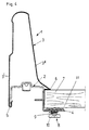
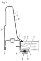
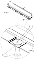
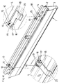
- a drawer frame 1 according to the invention is more conventional Way with two drawer frames 1, a base plate 7, a drawer rear wall and a front panel.
- the figures of the drawings are only one drawer frame 1 and the base plate 7 shown, the other parts the drawer are designed according to the conventional state of the art.
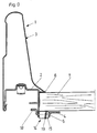
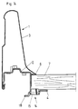
- Each drawer frame 1 consists of an upper part 3 and a lower part 2, wherein the lower part 2 a support part in the form of a support web 4 for the base plate 7 has.
- the lower part 2 of the drawer frame 1 can be used as a pull-out rail for a pull-out guide set be carried out or there can be a separate pull-out rail in this Lower part 2 can be attached.
- the upper part 3 of the drawer frame 1 is double-walled with an outer wall 3 'and an inner wall 3' '.
- a cover lip 6 is formed, which in the mounting position Side edge of the base plate 7 covers and thus prevents dirt particles in the Penetrate gap between the base plate 7 and the lower part 2 of the drawer 1.
- the drawer frame 1 is made of metal, preferably Sheet steel, and the bottom plate 7 made of a wood material, for example a chipboard.
- the holding devices 8 comprise clamping parts which can be rotated about a vertical axis (the expressions vertical "and horizontal "refer to the position of use of the drawer in the furniture body).
- the clamping parts are designed as bolts 9, which are provided with a thread and are supported in a nut thread 21 of the support web 4 of the drawer frame 1 or of the lower frame part 2.
- Two clamping parts or bolts 9 are advantageously provided per drawer frame 1, where a clamping part at the front end of the drawer frame 1 and the second Clamping parts located at or near the rear end of the drawer frame 1.
- Each bolt 9 is provided with a handle 10 located below the support web 4, which is designed as a one-armed lever. On his facing the base plate 7 On the side, the holding device 8 has a pressure plate 11 which is immediate is formed on the bolt 9.
- the handle 10 If the handle 10 is rotated and the pressure plate 11 is raised, it presses the base plate 7 against the cover lip 6, which serves as a stop for the base plate 7.
- the Bottom plate 7 is therefore firmly clamped between the cover lip 6 and the bolt 9 the holding device 8 held.
- the clamping part or the pressure plate 11 presses on the flat underside of the base plate 7, which has no grooves or hangers.
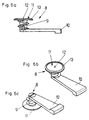
- the pressure plate 11 can also be used be provided with claw-like holding means, for example with one in the middle of the Pressure plates 11 arranged center 12 or with the edge of Pressure plate 11 surrounding cutting ring 13.
- a pressure plate 11 can either be a Grain tip 12 or a cutting ring 13 or, as in FIGS. 5 and 6 shown, provided both with a center point 12 and with a cutting ring 13 be.
- the handle 10 of the holding device 8 is preferred aligned parallel to the drawer frame 1, d. H. it is from the support footbridge 4 covered.
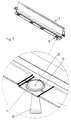
- the drawer frame 1 is designed analogously to the previously described exemplary embodiment, with a double-walled upper part 3 and a lower part 2, on which the support web 4 is designed for the base plate 7.
- the clamping parts of the holding devices 14 are in turn mounted on the support web 4.
- the support web 4 has two protruding downwards Provide tabs 16 in which the axis 17 of the respective roller 15 is added is.
- the rollers 15 are aligned horizontally, with the longitudinal central axis of the at the rear end of the drawer frame 1 arranged roller 15 in the longitudinal direction the drawer frame 1 extends while at the front end of the Drawer frame 1 arranged roller 15 aligned transversely to the drawer frame 1 is.
- the drawer frame 1 is again with two holding devices 14, d. H. provided with two rollers 15.
- Each roller 15 has a handle 18, which enables a manual and tool-free rotation of the roller 15.
- the roller 15 arranged at the rear end of the drawer frame 1 has two Providing cutting rings 19, when clamping the base plate 7 in the wood material the bottom plate 7 penetrate the roller 15 at the front end of the
- the drawer frame 1 arranged holding device 14 has only one cutting ring 19 on, and this is formed in half of the roller 15, the inner Wall of the drawer frame 1 has.
- the handle 18 of the rear holding device 14 In the position in which the base plate 7 between the support web 4 and the cover lip 6 can be inserted, the handle 18 of the rear holding device 14 in the position shown in FIG. 11. To fix the base plate 7 the handle 18 is pivoted and the roller 15 rotated. In the cocking position the handle 18 is in the position shown in FIG. 12. The Cutting rings 19 of the roller 15 pressed into the wood material of the base plate 7 and the base plate 7 is pressed against the cover lip 6.
- the handles 18 are included angled ends 20 provided.
- rollers 15, which are used at the front end of the drawer 1 depending on whether it is the right or left drawer frame 1 acts differently trained, d. H. the cutting ring 19 is in each case opposite End of the roller 15 arranged.
Landscapes
- Drawers Of Furniture (AREA)
- Clamps And Clips (AREA)
- Patch Boards (AREA)
- Casings For Electric Apparatus (AREA)
- Valve Device For Special Equipments (AREA)
- Special Wing (AREA)
- Television Systems (AREA)
- Time-Division Multiplex Systems (AREA)
Priority Applications (1)
| Application Number | Priority Date | Filing Date | Title |
|---|---|---|---|
| AT99111106T ATE296558T1 (de) | 1998-06-24 | 1999-06-08 | Schubladenzarge |
Applications Claiming Priority (2)
| Application Number | Priority Date | Filing Date | Title |
|---|---|---|---|
| AT0109298A AT409072B (de) | 1998-06-24 | 1998-06-24 | Schubladenzarge |
| AT109298 | 1998-06-24 |
Publications (3)
| Publication Number | Publication Date |
|---|---|
| EP0966903A2 true EP0966903A2 (fr) | 1999-12-29 |
| EP0966903A3 EP0966903A3 (fr) | 2003-12-17 |
| EP0966903B1 EP0966903B1 (fr) | 2005-06-01 |
Family
ID=3506415
Family Applications (1)
| Application Number | Title | Priority Date | Filing Date |
|---|---|---|---|
| EP99111106A Expired - Lifetime EP0966903B1 (fr) | 1998-06-24 | 1999-06-08 | Cadre de tiroir |
Country Status (5)
| Country | Link |
|---|---|
| US (1) | US6095627A (fr) |
| EP (1) | EP0966903B1 (fr) |
| AT (2) | AT409072B (fr) |
| DE (1) | DE59912104D1 (fr) |
| ES (1) | ES2242328T3 (fr) |
Cited By (3)
| Publication number | Priority date | Publication date | Assignee | Title |
|---|---|---|---|---|
| AT512383A1 (de) * | 2011-12-22 | 2013-07-15 | Blum Gmbh Julius | Doppelwandige schubladenzarge mit einer innenwand und einer aussenwand |
| WO2015172164A1 (fr) * | 2014-05-14 | 2015-11-19 | Julius Blum Gmbh | Paroi latérale de tiroir |
| CN109561761A (zh) * | 2016-08-15 | 2019-04-02 | 保罗海蒂诗有限及两合公司 | 用于抽屉的边框 |
Families Citing this family (22)
| Publication number | Priority date | Publication date | Assignee | Title |
|---|---|---|---|---|
| DE19944643A1 (de) * | 1999-09-17 | 2001-03-22 | Hettich Paul Gmbh & Co | Befestigungsanordnung |
| AU1471401A (en) | 1999-11-05 | 2001-05-14 | University Of Utah Research Foundation | Degradation of polycyclic aromatic hydrocarbons |
| DE20209416U1 (de) * | 2002-06-17 | 2003-10-30 | Alfit AG, Götzis | Anordnung für die Verbindung einer Schubladenzarge mit dem Boden einer Schublade |
| USD563125S1 (en) * | 2005-09-13 | 2008-03-04 | Julius Blum Gmbh | Side wall of a drawer |
| USD577936S1 (en) | 2005-09-13 | 2008-10-07 | Julius Blum Gmbh | Side wall of a drawer |
| USD572511S1 (en) * | 2007-05-07 | 2008-07-08 | Julius Blum Gmbh | Part of drawers |
| MY142138A (en) * | 2007-08-06 | 2010-09-30 | Harn Marketing Sdn Bhd | Drawer assembly |
| AT510773B1 (de) * | 2010-11-23 | 2014-09-15 | Blum Gmbh Julius | Schubladenanordnung mit einer an einem Schubladenbehälter vormontierten Behältnisschiene |
| ITMI20111454A1 (it) * | 2011-07-29 | 2013-01-30 | Salice Arturo Spa | Dispositivo di aggancio per il fissaggio di un cassetto ad una guida |
| USD746090S1 (en) * | 2013-08-02 | 2015-12-29 | Grass Gmbh | Side panel for furniture drawer |
| DE202013011422U1 (de) * | 2013-12-20 | 2015-03-23 | Grass Gmbh | Möbelschublade und Schubladenwandelement für eine Schublade |
| DE202013011426U1 (de) * | 2013-12-20 | 2015-03-23 | Grass Gmbh | Schubladenwandeelement |
| DE202014104929U1 (de) * | 2014-10-16 | 2016-01-19 | Grass Gmbh | Zarge für eine Schublade mit einem Zargenkörper sowie Schublade und Möbel mit einer Schublade |
| DE202014104923U1 (de) * | 2014-10-16 | 2016-01-19 | Grass Gmbh | Wandelement für eine Zarge sowie Zarge, Schublade und Möbel |
| DE202014104926U1 (de) * | 2014-10-16 | 2016-01-19 | Grass Gmbh | Wandbauteil, Schublade mit einem solchen Wandbauteil und Möbel |
| TWI531342B (zh) * | 2015-11-12 | 2016-05-01 | 川湖科技股份有限公司 | 抽屜側牆組件 |
| AT520804B1 (de) * | 2017-12-19 | 2023-04-15 | Blum Gmbh Julius | Doppelwandige Schubladenseitenwand |
| AT520734B1 (de) * | 2018-02-01 | 2019-07-15 | Blum Gmbh Julius | Ladenschiene für eine Schubladenausziehführung |
| USD1070442S1 (en) * | 2020-05-29 | 2025-04-15 | Grass Gmbh | Side wall for a drawer |
| USD1070443S1 (en) * | 2020-05-29 | 2025-04-15 | Grass Gmbh | Side wall for a drawer |
| DE102020119901A1 (de) * | 2020-07-28 | 2022-02-03 | Paul Hettich Gmbh & Co. Kg | Adaptereinheit zur Verbindung eines Schubkastenbodens mit einer Seitenzarge eines Schubkastens, Seitenzarge und Schubkasten |
| DE102023130076A1 (de) * | 2023-10-31 | 2025-04-30 | Paul Hettich Gmbh & Co. Kg | Schubkasten |
Citations (2)
| Publication number | Priority date | Publication date | Assignee | Title |
|---|---|---|---|---|
| EP0429428A2 (fr) | 1989-11-20 | 1991-05-29 | Alfit Aktiengesellschaft | Tiroir |
| DE9303903U1 (de) | 1993-03-17 | 1994-04-14 | Grass AG, Höchst, Vorarlberg | Schublade mit Zarge und Schubladenboden |
Family Cites Families (5)
| Publication number | Priority date | Publication date | Assignee | Title |
|---|---|---|---|---|
| DE8510835U1 (de) * | 1985-04-13 | 1985-06-13 | Alfred Grass GmbH Metallwarenfabrik, Höchst, Vorarlberg | Schubladenkasten für Ausziehführungen |
| DE3942897A1 (de) * | 1989-12-23 | 1991-06-27 | Grass Ag | Schublade |
| DE9216508U1 (de) * | 1992-12-03 | 1993-02-25 | Grass AG, Höchst, Vorarlberg | Schublade mit Befestigung für einen Schubladenboden |
| AT401856B (de) * | 1993-05-13 | 1996-12-27 | Blum Gmbh Julius | Schublade |
| DE19717184B4 (de) * | 1997-04-24 | 2004-02-26 | Grass Gmbh | Schublade |
-
1998
- 1998-06-24 AT AT0109298A patent/AT409072B/de not_active IP Right Cessation
-
1999
- 1999-06-08 DE DE59912104T patent/DE59912104D1/de not_active Expired - Lifetime
- 1999-06-08 AT AT99111106T patent/ATE296558T1/de not_active IP Right Cessation
- 1999-06-08 EP EP99111106A patent/EP0966903B1/fr not_active Expired - Lifetime
- 1999-06-08 ES ES99111106T patent/ES2242328T3/es not_active Expired - Lifetime
- 1999-06-22 US US09/337,545 patent/US6095627A/en not_active Expired - Lifetime
Patent Citations (2)
| Publication number | Priority date | Publication date | Assignee | Title |
|---|---|---|---|---|
| EP0429428A2 (fr) | 1989-11-20 | 1991-05-29 | Alfit Aktiengesellschaft | Tiroir |
| DE9303903U1 (de) | 1993-03-17 | 1994-04-14 | Grass AG, Höchst, Vorarlberg | Schublade mit Zarge und Schubladenboden |
Cited By (5)
| Publication number | Priority date | Publication date | Assignee | Title |
|---|---|---|---|---|
| AT512383A1 (de) * | 2011-12-22 | 2013-07-15 | Blum Gmbh Julius | Doppelwandige schubladenzarge mit einer innenwand und einer aussenwand |
| AT512383B1 (de) * | 2011-12-22 | 2016-06-15 | Blum Gmbh Julius | Doppelwandige schubladenzarge mit einer innenwand und einer aussenwand |
| US9456690B2 (en) | 2011-12-22 | 2016-10-04 | Julius Blum Gmbh | Double-walled drawer frame with an inner wall and an outer wall |
| WO2015172164A1 (fr) * | 2014-05-14 | 2015-11-19 | Julius Blum Gmbh | Paroi latérale de tiroir |
| CN109561761A (zh) * | 2016-08-15 | 2019-04-02 | 保罗海蒂诗有限及两合公司 | 用于抽屉的边框 |
Also Published As
| Publication number | Publication date |
|---|---|
| AT409072B (de) | 2002-05-27 |
| EP0966903B1 (fr) | 2005-06-01 |
| EP0966903A3 (fr) | 2003-12-17 |
| ATE296558T1 (de) | 2005-06-15 |
| DE59912104D1 (de) | 2005-07-07 |
| ATA109298A (de) | 2001-10-15 |
| ES2242328T3 (es) | 2005-11-01 |
| US6095627A (en) | 2000-08-01 |
Similar Documents
| Publication | Publication Date | Title |
|---|---|---|
| EP0966903B1 (fr) | Cadre de tiroir | |
| EP0244582B1 (fr) | Eléments de construction pour meuble | |
| EP0537151A1 (fr) | Kit pour monter des tables de travail et des bureaux. | |
| DE4100675A1 (de) | Moebelstueck zur aufnahme von monitoren | |
| DE4102363A1 (de) | Montagevorrichtung fuer gelenkarmmarkise | |
| DE102008057170B4 (de) | Schublade und Adapterelement | |
| DE10163182A1 (de) | Befestigungselement zum Befestigen eines Haushaltgeräts | |
| DE4428937C2 (de) | Computermöbel | |
| EP0503234A1 (fr) | Guidage pour tiroirs, de préférence en métal | |
| EP0019833B1 (fr) | Fixation de manche détachable pour balais ou balais-brosses | |
| EP0413396B1 (fr) | Appareil domestique, notamment machine à laver le vaiselle | |
| DE7530601U (de) | Halterung fuer einen wandschrank | |
| DE29701179U1 (de) | Reinigungsgerät | |
| DE9210602U1 (de) | Befestigungselement für Verkleidungselemente | |
| DE2752580A1 (de) | Befestigungsvorrichtung fuer tablars und haengeschraenke | |
| DE19920918C2 (de) | Toilettensitzerhöhung | |
| DE60000313T2 (de) | Befestigungssystem an einer Säule für ein Trägerelement | |
| DE1154245B (de) | Halter zum Befestigen von Tragschienen fuer Gardinen, Vorhaenge u. dgl. | |
| EP0213236A2 (fr) | Dispositif de type rayonnage | |
| DE8619968U1 (de) | Arbeitstisch, insbesondere Bürotisch | |
| DE2331976C2 (de) | Trennwand | |
| EP1249192A1 (fr) | Chaise | |
| DE29510298U1 (de) | Anordnung einer Schraubverbindung | |
| AT527379A1 (de) | Stützvorrichtung zum Abstützen eines Schubladenbodens | |
| DE4207134A1 (de) | Regal |
Legal Events
| Date | Code | Title | Description |
|---|---|---|---|
| PUAI | Public reference made under article 153(3) epc to a published international application that has entered the european phase |
Free format text: ORIGINAL CODE: 0009012 |
|
| AK | Designated contracting states |
Kind code of ref document: A2 Designated state(s): AT BE CH CY DE DK ES FI FR GB GR IE IT LI LU MC NL PT SE |
|
| AX | Request for extension of the european patent |
Free format text: AL;LT;LV;MK;RO;SI |
|
| RIN1 | Information on inventor provided before grant (corrected) |
Inventor name: SUTTERLUETTI, HAROLD |
|
| PUAL | Search report despatched |
Free format text: ORIGINAL CODE: 0009013 |
|
| AK | Designated contracting states |
Kind code of ref document: A3 Designated state(s): AT BE CH CY DE DK ES FI FR GB GR IE IT LI LU MC NL PT SE |
|
| AX | Request for extension of the european patent |
Extension state: AL LT LV MK RO SI |
|
| RIC1 | Information provided on ipc code assigned before grant |
Ipc: 7A 47B 88/04 B Ipc: 7A 47B 88/00 A |
|
| 17P | Request for examination filed |
Effective date: 20040308 |
|
| AKX | Designation fees paid |
Designated state(s): AT DE ES IT |
|
| GRAP | Despatch of communication of intention to grant a patent |
Free format text: ORIGINAL CODE: EPIDOSNIGR1 |
|
| GRAS | Grant fee paid |
Free format text: ORIGINAL CODE: EPIDOSNIGR3 |
|
| GRAA | (expected) grant |
Free format text: ORIGINAL CODE: 0009210 |
|
| RAP1 | Party data changed (applicant data changed or rights of an application transferred) |
Owner name: JULIUS BLUM GMBH |
|
| AK | Designated contracting states |
Kind code of ref document: B1 Designated state(s): AT DE ES IT |
|
| PG25 | Lapsed in a contracting state [announced via postgrant information from national office to epo] |
Ref country code: AT Free format text: LAPSE BECAUSE OF NON-PAYMENT OF DUE FEES Effective date: 20050608 |
|
| REG | Reference to a national code |
Ref country code: IE Ref legal event code: FG4D Free format text: LANGUAGE OF EP DOCUMENT: GERMAN |
|
| REF | Corresponds to: |
Ref document number: 59912104 Country of ref document: DE Date of ref document: 20050707 Kind code of ref document: P |
|
| REG | Reference to a national code |
Ref country code: ES Ref legal event code: FG2A Ref document number: 2242328 Country of ref document: ES Kind code of ref document: T3 |
|
| PLBE | No opposition filed within time limit |
Free format text: ORIGINAL CODE: 0009261 |
|
| STAA | Information on the status of an ep patent application or granted ep patent |
Free format text: STATUS: NO OPPOSITION FILED WITHIN TIME LIMIT |
|
| 26N | No opposition filed |
Effective date: 20060302 |
|
| PGFP | Annual fee paid to national office [announced via postgrant information from national office to epo] |
Ref country code: DE Payment date: 20180831 Year of fee payment: 20 Ref country code: ES Payment date: 20180723 Year of fee payment: 20 Ref country code: IT Payment date: 20180622 Year of fee payment: 20 |
|
| REG | Reference to a national code |
Ref country code: DE Ref legal event code: R071 Ref document number: 59912104 Country of ref document: DE |
|
| REG | Reference to a national code |
Ref country code: ES Ref legal event code: FD2A Effective date: 20200721 |
|
| PG25 | Lapsed in a contracting state [announced via postgrant information from national office to epo] |
Ref country code: ES Free format text: LAPSE BECAUSE OF EXPIRATION OF PROTECTION Effective date: 20190609 |