EP0967031A2 - Vorrichtung zum Herstellen von Taschenfedern - Google Patents
Vorrichtung zum Herstellen von Taschenfedern Download PDFInfo
- Publication number
- EP0967031A2 EP0967031A2 EP98310364A EP98310364A EP0967031A2 EP 0967031 A2 EP0967031 A2 EP 0967031A2 EP 98310364 A EP98310364 A EP 98310364A EP 98310364 A EP98310364 A EP 98310364A EP 0967031 A2 EP0967031 A2 EP 0967031A2
- Authority
- EP
- European Patent Office
- Prior art keywords
- coil spring
- coil
- coil springs
- sheet
- cased
- Prior art date
- Legal status (The legal status is an assumption and is not a legal conclusion. Google has not performed a legal analysis and makes no representation as to the accuracy of the status listed.)
- Withdrawn
Links
Images





Classifications
-
- B—PERFORMING OPERATIONS; TRANSPORTING
- B21—MECHANICAL METAL-WORKING WITHOUT ESSENTIALLY REMOVING MATERIAL; PUNCHING METAL
- B21F—WORKING OR PROCESSING OF METAL WIRE
- B21F33/00—Tools or devices specially designed for handling or processing wire fabrics or the like
- B21F33/04—Connecting ends of helical springs for mattresses
-
- B—PERFORMING OPERATIONS; TRANSPORTING
- B68—SADDLERY; UPHOLSTERY
- B68G—METHODS, EQUIPMENT, OR MACHINES FOR USE IN UPHOLSTERING; UPHOLSTERY NOT OTHERWISE PROVIDED FOR
- B68G9/00—Placing upholstery springs in pockets; Fitting springs in upholstery
-
- B—PERFORMING OPERATIONS; TRANSPORTING
- B68—SADDLERY; UPHOLSTERY
- B68G—METHODS, EQUIPMENT, OR MACHINES FOR USE IN UPHOLSTERING; UPHOLSTERY NOT OTHERWISE PROVIDED FOR
- B68G9/00—Placing upholstery springs in pockets; Fitting springs in upholstery
- B68G2009/005—Devices for turning the springs 90° inside the pockets
-
- Y—GENERAL TAGGING OF NEW TECHNOLOGICAL DEVELOPMENTS; GENERAL TAGGING OF CROSS-SECTIONAL TECHNOLOGIES SPANNING OVER SEVERAL SECTIONS OF THE IPC; TECHNICAL SUBJECTS COVERED BY FORMER USPC CROSS-REFERENCE ART COLLECTIONS [XRACs] AND DIGESTS
- Y10—TECHNICAL SUBJECTS COVERED BY FORMER USPC
- Y10T—TECHNICAL SUBJECTS COVERED BY FORMER US CLASSIFICATION
- Y10T29/00—Metal working
- Y10T29/51—Plural diverse manufacturing apparatus including means for metal shaping or assembling
- Y10T29/5186—Covering
-
- Y—GENERAL TAGGING OF NEW TECHNOLOGICAL DEVELOPMENTS; GENERAL TAGGING OF CROSS-SECTIONAL TECHNOLOGIES SPANNING OVER SEVERAL SECTIONS OF THE IPC; TECHNICAL SUBJECTS COVERED BY FORMER USPC CROSS-REFERENCE ART COLLECTIONS [XRACs] AND DIGESTS
- Y10—TECHNICAL SUBJECTS COVERED BY FORMER USPC
- Y10T—TECHNICAL SUBJECTS COVERED BY FORMER US CLASSIFICATION
- Y10T29/00—Metal working
- Y10T29/51—Plural diverse manufacturing apparatus including means for metal shaping or assembling
- Y10T29/5191—Assembly
Definitions
- the present invention relates to an apparatus for producing the so-called cased coil springs for use in mattresses and chairs which are cased in casings (bags) which are successively formed in a pocket form from a sheet of a non-woven fabric or a cloth.
- a conventional type of cased coil spring producing apparatus is not equipped with any hardening device for hardening the coil springs, and thus it has the problem of the produced coil springs being weak in resiliency and thus has a durability problem.
- an expensive, oil-tempered, wire rod is used in forming the coil springs, but since the oil-tempered wire rod has a strong resiliency, it takes much time and labor in forming the oil-tempered wire rod into a coiled form, thus reducing productivity and thus increasing manufacturing costs of the coil springs, combined with the expensive wire rod.
- the formed coil springs are put into a compressed state and then are inserted in the casings.
- a large-stroke cylinder rod having at its tip end thereof a circular compressing plate has been generally used.
- the coil springs after thrown in cylindrical guides to be in a vertical position, are each compressed with the compressing plate from above by a force of the cylinder rod and then pushed at an outer diameter portion thereof to be inserted in the casing.
- This conventional way involves the problem of low productivity, because the feeding of a next coil spring cannot be done until the compressing plate is raised up.
- the applicant previously proposed a pocket coil spring producing apparatus (US Patent Publication No. 5,740,597, corresponding to the Japanese Laid-open Patent Publication No. Hei 9(1997)-173673).
- the proposed apparatus has however the disadvantage that when the production speed of the pocket coil spring producing apparatus is increased for increase of productivity, the coil spring producing mechanism will show a tendency of errors in cutting of the wire. It also has undesirable tendencies of delays in hardening and conveying and compression and insertion of the coil springs formed in the coil spring producing mechanism and of mistakes in the process of laying down the coil springs as compressed vertically in the sheet casings or bags to their horizontal position.
- the present invention has been made based on the applicant's previous proposal, with the aim to provide improved productivity and provide a high-grade mattress or equivalent having a partially different repulsion.
- a cased coil spring producing apparatus comprises a coil spring producing mechanism for forming coil springs; a conveying mechanism including a conveyer for conveying the coil springs fed from the coil spring producing mechanism; a hardening-and-cooling mechanism for hardening the coil springs and cooling them; a sheet feeding mechanism for double folding a sheet and feeding it; a compression-and-insertion mechanism for compressing the coil springs and inserting them in the double folded sheet; a bonding mechanism for bonding the double folded sheet inserting therein the coil springs together; and a coil spring arraying mechanism for changing position of the coil springs inserted in the sheet.
- the conveyer of the conveying mechanism includes coil spring supporting members aligned in two or more rows rising upwardly therefrom, and also a sorting mechanism is provided for sortably distributing the coil springs fed from the coil spring producing mechanism to the coil spring supporting members.
- the coil spring producing mechanism comprises a device capable of changing a pitch of each of coil springs formed in the process of forming the coil springs.
- the coil spring producing mechanism includes a cutter for cutting a wire of the springs successively formed into a coil form, and the cutter has a cutting edge and a separation pawl for separating a terminal end of an earlier coil spring from a leading end of the next coil spring before the cutter edge goes into action and is so structured as to be movable between an operating position of the separation pawl and an operating position of the cutting edge.
- the coil spring producing mechanism is so structured that the coil springs can be changed in pitch by a wire guide member being changed in position while a terminal end of an earlier coil spring is separated from a leading end of the next coil spring and/or while a wire is formed into a coil form.
- the compression-and-insertion mechanism comprises a compressing member for compressing each row of coil springs by pressing from above; a driving mechanism for driving the compressing member for the pressing of the coil springs; and a carrying member for carrying the compressed coil springs to a shoot guide.
- the coil spring arraying mechanism is composed of rotating blades having an action to slant the compressed coil springs in the sheets by pushing the coil springs at the upper portions thereof and an action to lay the slanted coil springs down to a horizontal position to array the coil springs in order.
- the sheet feeding mechanism is so structured that at a sheet fold-back portion at which the sheet fed from a sheet roll is folded back or in proximity to the sheet fold-back portion, the sheet is folded approximately half of the width of the sheet at a first folding portion and further this folded part of the sheet is folded at a second folding portion at an angle of generally 90 degree with respect to the first folding portion so that the folded part can be laid over or under the part of the sheet folded at the fold-back portion.
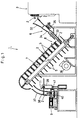
- FIG. 1 is a schematic side view of a cased coil spring producing apparatus and FIG. 2 is a front view of the same.
- Numeral 1 in the illustration shows the entirety of the cased coil spring producing apparatus.
- the cased coil spring producing apparatus 1 comprises a coil spring producing mechanism 3 for forming coil springs 2 from a wire; a coil spring sorting mechanism 6 for alternately distributing the coil springs 3 fed from the coil spring producing mechanism 3 to coil spring supporting bars 5 embedded in two rows in a conveyer 4; a conveying mechanism 7 including the conveyer 4 for conveying the coil springs 2 fed from the coil spring sorting mechanism 6 with their supported by the supporting bars 5; a hardening-and-cooling mechanism 8 for successively hardening the coil springs 2 and cooling them by blowing in the process of conveyance; a sheet feeding mechanism 10 for feeding a double folded sheet 9 in which the coil springs are inserted; a compression-and-insertion mechanism 11 for simultaneously compressing a plurality of coil springs 2 as hardened and cooled and inserting them in the double folded sheet 9; a bonding mechanism 12 for bonding the double folded sheet 9 inserting therein the coil springs 2 together, to form generally rectangular sheet casings or bags for casing therein the coil springs 2;
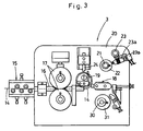
- the wire 14 is fed through a wire guide 16 to a round tool 18 via a pair of wire feed rollers 17 and is formed into a circular-arc form thereat. Then, the wire 14 formed into the circular-arc form is pressed at one end thereof by a pitch tool 19, to be formed into a coil having a prescribed pitch.
- the pitch tool 19 also acts as a device for making changes in pitch and height of the coil springs.
- the change in pitch of the coils thus successively formed are made by an operating shaft 23 being rotated by a pitch adjuster 23a which is shifted sliding in contact with a profile (a cam surface) of a pitch adjusting eccentric cam 22 which is assembled to a shaft 21 rotatably pivoted by a frame 20 of a part of the coil spring producing mechanism 3.
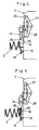
- the coil spring 2 When the pressing force of the pitch tool 19 to the wire 14 is strong, the coil spring 2 will have a large pitch, as shown in FIG. 4, and when the pressing force is decreased, the coil spring 2 will have a small pitch or zero pitch, as shown in FIG. 5.
- the pitch of the coil springs can be variously changed by changing the position of the pitch adjuster 23a by a cylinder 23b in the course of producing the coil springs.
- the round tool 18 is moved rightward or leftward in FIG. 3 in a swinging manner via an eccentric cam 31 which is assembled to a coil diameter adjusting shaft 30 pivoted by the frame 20 of a part of the coil spring producing mechanism 3.
- the coil spring 2 formed When the round tool 18 is moved leftward, the coil spring 2 formed will have a reduced outer diameter; and when the round tool 18 is moved rightward, the coil spring 2 will have an increased outer diameter.
- the coil spring 2 of a barrel shape as shown in FIG. 5 or a hand-drum shape as opposed to the barrel shape, not shown, can be formed with ease.
- the cutter 24 is disposed at an upper end portion of the coil spring 2 formed by the coil spring producing mechanism 3.
- the cutter 24 has a cutting edge 25 and an integrally formed separation pawl 26, located at the tip end portion of the cutter, for separating a terminal end of an earlier coil spring from a leading end of the next coil spring, as shown in FIGS. 4 to 8.
- the cutter is so structured as to be movable between an operating position of the separation pawl 26 and an operating position of the cutting edge 25.
- a cutter operating cam 27 is provided in the frame at the side of the coil spring producing mechanism 3.
- a cam slot 28 slotted in the cutter operating cam 27 controls the cutter 24 to move between a first position at which the separation pawl 26 projects and a second position at which the separation pawl further projects as far as the cutting edge 25 cuts the wire of the coil spring 2.
- the cutter operating cam 27 is operated to insert the separation pawl 26 in a space between coils, to expand the space between the coil and the adjoining wire to be cut (See FIG. 8).
- the pitch adjusting eccentric cam 22 is adjusted so that even when the pitch of the coil spring 2 is reduced to zero or less, i.e., even when the terminal end of the coil spring or a leading end of the next coil spring comes into the inside, or when the cutter 24 is moved further to bring the cutting edge 25 into action, the wire can be cut at a specified position without errors in cutting.
- the coil springs 2 thus cut by use of the cutter 24 are fed from a shooter 32 opening in front of the cutter to the conveyer 4 of the conveying mechanism 7 through the sorting mechanism 6 and a feeding guide 33.
- the coil spring supporting bars 5, 5 in two rows are embedded in the conveyer 4 of the conveying mechanism 7.
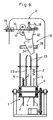
- the sorting mechanism 6 for sortably distributing the coil springs 2, 2 to the two rows of coil spring supporting bars 5, 5 is provided between the shooter 32 and the feeding guide 33, as shown in FIG. 9.
- the sorting mechanism comprises a cylindrical guide portion 34 for guiding the coil springs.
- the cylindrical guide portion 34 is rotatably pivoted nearly at an upper edge portion thereof, so that a lower portion of the cylindrical guide portion 34 is selectively swung between the two rows of coil spring supporting bars 5, 5 by a cylinder 35 provided under the pivot point of the cylindrical guide portion 34.
- the hardening-and-cooling mechanism 8, via which the coil springs 2 fed to the conveyer 4 of the conveying mechanism 7 are hardened and cooled on their way to the compression-and-insertion mechanism 11, comprises electrodes and a blower 36.
- the electrodes are brought into contact with the coil springs 2 at upper and lower portions thereof, to pass a current through the coil springs 2 from the electrodes so that the coil springs can be heated and thus hardened.
- the coil springs 2 are cooled down to generally atmospheric temperature by the blower 36 for sending air to the coil springs 2, before the coil springs 2 are fed to the following compression-and-insertion mechanism 11.
- the compression-and-insertion mechanism 11 comprises frame shooters 37 to which the coil springs supported by the coil spring supporting bars 5, 5 are fed therefrom when the conveyer 4 turns around at the upper turn and the coil spring supporting bars 5 points downward, as shown in FIG. 1; plate-like compressing members 38 with which the coil springs 2 fed into the frame shooters 37 are pressed from above into a compressed form; a driving mechanism 39 for driving the compressing members 38 to rotate and move up and down; shoot guides 40 having a cross section like the horizontally oriented letter U (FIG.
- the sheet 9 fed from a sheet roll 42 of a non-woven fabric in strip form is folded back at one end 43 (at the left side) of the cased coil spring producing apparatus 1, as shown in FIGS. 2 and 10.
- the sheet 9 is first folded approximately half of the width of the sheet at a first folding portion 44 and further this folded part of the sheet is folded at a second folding portion 45 so that the part as folded twice can be laid over or under the part of the sheet folded at the fold-back portion 43.
- the angle formed between the first folding portion 44 and the second folding portion 45 is generally 90 degree.
- the doubled sheets 9 inserting therein the compressed coil springs 2 are sealed at their parts at the side of the coil springs 2 and at their openings for insertion of the coil springs 2 by fusing or adhesive bonding via the bonding mechanism 12, with the coil springs kept compressed, and the resultant sheet casings are fed to the coil spring arraying mechanism 13 through sheet feed rollers 46.
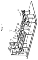
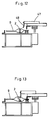
- the coil springs 2 compressed to be in a vertical position in the sheet casings fed through the sheet feed rollers 46 are pushed at their upper end portions by a push-down plate 48 fixed to an air cylinder 47, as shown in FIGS. 2, 11 and 12, and thereby are slanted, as shown in FIG. 13.
- the slanted coil springs 2 are tapped at their upper end portions by rotating blades 50 rotated by a motor 49 to be fallen out so that the axes of the coil springs 2 can be oriented horizontally (See FIGS. 14 and 15).
- the air cylinder 47 for actuating the push-down plate 48 and bearings 52 of a rotary shaft 51 of the rotating blades 50 are fixed to a fixing plate 53, and the fixing plate 53 is fixed to an elevating air cylinder 54. While the products are fed forward by the sheet feeding rollers 46, the push-down plate 48 and the rotating blades 50 are put in their raised position by the elevating air cylinder 54 not to hinder the feeding of the products (See FIG. 10).
- cased coil springs 2 thus formed are aligned in row, and a number of cased coil springs in row can be bonded to each other at the side wall portions thereof by application of adhesive thereto to thereby produce a spring structure for a bed, for example.
- the coil spring supporting members are arrayed in rows standing on the conveyer of the conveying mechanism, and the coil spring sorting mechanism is provided for sortably distributing the coil springs fed from the coil spring producing mechanism to the coil spring supporting members.
- This arrangement enables the hardening-and-cooling step to be effected by two or more at a time, even when the production speed of the coil spring producing mechanism is increased. This can produce the advantage of producing effectiveness of improvement in productivity, without delays in the hardening-and-conveying and in the compression-and-insertion of the coil springs, as in the prior art.
- the cased coil spring producing apparatus includes the device capable of instantaneously changing height (pitch) of each of the springs formed by the coil spring producing mechanism in the process of producing the coil springs. This enables the row of the cased coil springs to have a partially different repulsion, thus producing the advantage of providing a high-grade mattress having a partially different repulsion.
- the coil spring producing mechanism includes the cutter for cutting a wire, which includes the cutting edge and the separation pawl for separating a terminal end of an earlier coil spring from a leading end of the next coil spring before the cutter edge goes into action and which is so structured as to be movable between an operating position of the separation pawl and an operating position of the cutting edge.
- the coil spring arraying mechanism which is composed of the rotating blades having an action to slant the coiled springs compressed to be in the vertical position in the sheets by pushing the coil springs at the upper portions thereof and an action to lay the slanted coil springs down horizontally to array the coil springs in order, can produce the advantage that the position change of the coil springs can reliably be made with simplified structure.
- the sheet feeding mechanism is so structured that at a sheet fold-back portion at which the sheet fed from the sheet roll is folded back or in proximity to the sheet fold-back portion, the sheet is folded approximately half of the width of the sheet at the first folding portion and further this folded part of the sheet is folded at the second folding portion at an angle of generally 90 degree with respect to the first folding portion so that the folded part can be laid over or under the part of the sheet folded at the folding portion.
Landscapes
- Engineering & Computer Science (AREA)
- Mechanical Engineering (AREA)
- Wire Processing (AREA)
- Mattresses And Other Support Structures For Chairs And Beds (AREA)
- Heat Treatment Of Articles (AREA)
Applications Claiming Priority (2)
| Application Number | Priority Date | Filing Date | Title |
|---|---|---|---|
| JP10181077A JP2000015377A (ja) | 1998-06-26 | 1998-06-26 | 収納型コイルバネ製造装置 |
| JP18107798 | 1998-06-26 |
Publications (2)
| Publication Number | Publication Date |
|---|---|
| EP0967031A2 true EP0967031A2 (de) | 1999-12-29 |
| EP0967031A3 EP0967031A3 (de) | 2000-01-05 |
Family
ID=16094416
Family Applications (1)
| Application Number | Title | Priority Date | Filing Date |
|---|---|---|---|
| EP98310364A Withdrawn EP0967031A3 (de) | 1998-06-26 | 1998-12-17 | Vorrichtung zum Herstellen von Taschenfedern |
Country Status (3)
| Country | Link |
|---|---|
| US (1) | US6119322A (de) |
| EP (1) | EP0967031A3 (de) |
| JP (1) | JP2000015377A (de) |
Cited By (9)
| Publication number | Priority date | Publication date | Assignee | Title |
|---|---|---|---|---|
| EP0976678A3 (de) * | 1998-07-31 | 2000-06-28 | Matsushita Industrial Co. Ltd. | Federkern für Möbel und Matratzen und Verfahren zu dessen Herstellung |
| WO2002038304A1 (en) * | 2000-11-10 | 2002-05-16 | Spühl AG St. Gallen | A method and installation for the transport of springs for spring interiors for mattresses or upholstery |
| WO2004009265A1 (en) * | 2002-07-19 | 2004-01-29 | Springform Technology Limited | Method and apparatus for manufacturing spring assemblies |
| FR2861615A1 (fr) * | 2003-10-29 | 2005-05-06 | Plastef Investissements | Dispositif de manipulation pour un objet, installation de manipulation d'un objet et procede pour manipuler un objet |
| CN103332433A (zh) * | 2013-06-24 | 2013-10-02 | 深圳市宝龙盛五金制品有限公司 | 具有新型输送系统并可液体冷却的床垫弹簧加工设备 |
| CN108057822A (zh) * | 2017-12-07 | 2018-05-22 | 佛山市顺德区奥丰弹簧有限公司 | 一种铰链弹簧的制作工艺 |
| US10206515B1 (en) | 2017-09-20 | 2019-02-19 | L&P Property Management Company | Pocketed spring assembly |
| CN110369640A (zh) * | 2019-07-15 | 2019-10-25 | 夏文凯 | 一种建筑工程用节能型钢筋切割设备 |
| CN117161275A (zh) * | 2023-10-30 | 2023-12-05 | 福州立洲弹簧有限公司 | 一种弹簧生产用卷簧装置 |
Families Citing this family (16)
| Publication number | Priority date | Publication date | Assignee | Title |
|---|---|---|---|---|
| KR100368070B1 (ko) * | 2000-04-28 | 2003-01-15 | 주식회사 대구정밀 | 다각형 코일스프링을 성형하기 위한 가이드 장치 |
| US6751933B2 (en) * | 2000-06-27 | 2004-06-22 | Spuhl Ag St. Gallen | Method and device for turning and relaxing springs |
| US6694554B2 (en) * | 2001-04-20 | 2004-02-24 | L&P Property Management Company | Fiber mass with side coil insertion |
| GB0519009D0 (en) * | 2005-09-17 | 2005-10-26 | Harrison Bedding Ltd | Pocketted spring units |
| JP4874373B2 (ja) * | 2009-09-09 | 2012-02-15 | 松下工業株式会社 | ポケットコイルバネ構造体組立装置 |
| EP2316783B1 (de) * | 2009-10-27 | 2012-10-03 | Spühl AG | Vorrichtung und Verfahren zum Überführen von Federn |
| US8912472B1 (en) | 2010-07-19 | 2014-12-16 | Barnes Group Inc. | Induction heating of springs |
| KR101184757B1 (ko) | 2010-07-27 | 2012-09-20 | 안정호 | 코일스프링 어셈블리의 제조를 위한 압축코일스프링의 포켓 내 자세조정장치 |
| CN103879604B (zh) * | 2014-03-05 | 2016-01-27 | 广州市联柔机械设备有限公司 | 一种袋装弹簧生产压缩输送机构 |
| US10577240B2 (en) * | 2017-04-17 | 2020-03-03 | Macao Commercial & Industrial Spring Mattress Manufacturer Macao TAIWA Machinery | Automatic bagged spring production apparatus |
| WO2022268920A1 (en) * | 2021-06-24 | 2022-12-29 | Sanofi Winthrop Industrie | Spring carrier |
| KR20240046430A (ko) * | 2021-06-24 | 2024-04-09 | 사노피 윈쓰롭 인더스트리 | 스프링 캐리어 |
| EP4359321A1 (de) * | 2021-06-24 | 2024-05-01 | Sanofi Winthrop Industrie | Federträger |
| KR102550827B1 (ko) * | 2023-01-09 | 2023-07-03 | 주식회사 시몬스 | 이중 포켓 스프링 제조장치 및 이중 포켓 스프링의 제조방법 |
| KR102550826B1 (ko) * | 2023-01-09 | 2023-07-03 | 주식회사 시몬스 | 포켓 스프링 조정 장치 |
| CN118726732B (zh) * | 2024-07-15 | 2025-03-18 | 深圳市以凡泰科技有限公司 | 一种用于镍钛合金弹簧的热处理设备 |
Family Cites Families (8)
| Publication number | Priority date | Publication date | Assignee | Title |
|---|---|---|---|---|
| US2032510A (en) * | 1934-03-28 | 1936-03-03 | Spuhl Julius | Machine for the manufacture of pocket bands containing upholstery springs |
| JPH0777655B2 (ja) * | 1992-07-24 | 1995-08-23 | 株式会社板屋製作所 | バネ製造装置 |
| US5572853A (en) * | 1994-08-15 | 1996-11-12 | Simmons Company | Method and apparatus for conditioning pocketed coil springs |
| US5613287A (en) * | 1995-06-07 | 1997-03-25 | Simmons Company | Method for forming strings of pocketed springs |
| JP2895791B2 (ja) * | 1995-12-25 | 1999-05-24 | 松下工業株式会社 | ポケットコイルバネ製造装置 |
| US5669093A (en) * | 1996-07-17 | 1997-09-23 | L & P Property Management Company | Pocketed coil spring assembly |
| JP3434994B2 (ja) * | 1996-12-12 | 2003-08-11 | 富士通株式会社 | セル組立多重化装置 |
| US5868383A (en) * | 1997-03-27 | 1999-02-09 | L&P Property Management Company | Multiple rate coil spring assembly |
-
1998
- 1998-06-26 JP JP10181077A patent/JP2000015377A/ja active Pending
- 1998-12-17 EP EP98310364A patent/EP0967031A3/de not_active Withdrawn
- 1998-12-31 US US09/223,714 patent/US6119322A/en not_active Expired - Lifetime
Cited By (18)
| Publication number | Priority date | Publication date | Assignee | Title |
|---|---|---|---|---|
| US6170807B1 (en) | 1998-07-31 | 2001-01-09 | Matsushita Industrial Co., Ltd. | Inner springs for use in furniture and bedding and a producing method therefor |
| EP0976678A3 (de) * | 1998-07-31 | 2000-06-28 | Matsushita Industrial Co. Ltd. | Federkern für Möbel und Matratzen und Verfahren zu dessen Herstellung |
| CH694635A5 (de) * | 2000-11-10 | 2005-05-13 | Spuehl Ag St Gallen | Verfahren und Anlage zum Transport von Federn für Federkerne für Matratzen oder Polster. |
| WO2002038304A1 (en) * | 2000-11-10 | 2002-05-16 | Spühl AG St. Gallen | A method and installation for the transport of springs for spring interiors for mattresses or upholstery |
| WO2004009265A1 (en) * | 2002-07-19 | 2004-01-29 | Springform Technology Limited | Method and apparatus for manufacturing spring assemblies |
| US8099845B2 (en) | 2003-10-29 | 2012-01-24 | Tech Group Europe Limited | Method of handling an article |
| WO2005046930A1 (fr) * | 2003-10-29 | 2005-05-26 | Plastef Investissements | Dispositif de manipulation pour un objet, installation de manipulation d'un objet et procede pour manipuler un objet |
| US7845056B2 (en) | 2003-10-29 | 2010-12-07 | Tech Group Europe Limited | Device for handling an article |
| FR2861615A1 (fr) * | 2003-10-29 | 2005-05-06 | Plastef Investissements | Dispositif de manipulation pour un objet, installation de manipulation d'un objet et procede pour manipuler un objet |
| US8127416B2 (en) | 2003-10-29 | 2012-03-06 | Tech Group Europe Limited | Device for handling an article |
| CN103332433A (zh) * | 2013-06-24 | 2013-10-02 | 深圳市宝龙盛五金制品有限公司 | 具有新型输送系统并可液体冷却的床垫弹簧加工设备 |
| CN103332433B (zh) * | 2013-06-24 | 2016-08-10 | 深圳市宝龙盛五金制品有限公司 | 具有新型输送系统并可液体冷却的床垫弹簧加工设备 |
| US10206515B1 (en) | 2017-09-20 | 2019-02-19 | L&P Property Management Company | Pocketed spring assembly |
| CN108057822A (zh) * | 2017-12-07 | 2018-05-22 | 佛山市顺德区奥丰弹簧有限公司 | 一种铰链弹簧的制作工艺 |
| CN110369640A (zh) * | 2019-07-15 | 2019-10-25 | 夏文凯 | 一种建筑工程用节能型钢筋切割设备 |
| CN110369640B (zh) * | 2019-07-15 | 2020-08-21 | 中国机械工业建设集团有限公司 | 一种建筑工程用节能型钢筋切割设备 |
| CN117161275A (zh) * | 2023-10-30 | 2023-12-05 | 福州立洲弹簧有限公司 | 一种弹簧生产用卷簧装置 |
| CN117161275B (zh) * | 2023-10-30 | 2024-02-13 | 福州立洲弹簧有限公司 | 一种弹簧生产用卷簧装置 |
Also Published As
| Publication number | Publication date |
|---|---|
| JP2000015377A (ja) | 2000-01-18 |
| US6119322A (en) | 2000-09-19 |
| EP0967031A3 (de) | 2000-01-05 |
Similar Documents
| Publication | Publication Date | Title |
|---|---|---|
| US6119322A (en) | Cased coil spring producing apparatus | |
| US10961112B2 (en) | Method and apparatus for the production of a pocketed spring unit | |
| EP0781726B1 (de) | Vorrichtung zur Herstellung von Taschenschraubenfedern | |
| EP1068147B1 (de) | Vorrichtung zur herstellung von taschenfedern | |
| US5988253A (en) | Press holding mechanism for use in pocket coil spring structure assembling apparatus | |
| US4565046A (en) | Apparatus for manufacturing pocketed coil springs | |
| US6170807B1 (en) | Inner springs for use in furniture and bedding and a producing method therefor | |
| CN110155932B (zh) | 袋装弹簧床网粘接组合装置、方法及袋装弹簧床网 | |
| WO1995024987A1 (en) | Apparatus for manufacturing mattresses and box springs | |
| EP0212466B1 (de) | Verfahren zum Bilden von Filterelementen und Apparat dafür | |
| CZ341495A3 (en) | Panel made of mineral wool, process of its manufacture and apparatus for making the same | |
| US4459733A (en) | Method and devices for assembly of helixes into face structures | |
| US6575457B2 (en) | Variable length sheet feeding mechanism | |
| US4121628A (en) | Spring forming machine | |
| US5125887A (en) | Device for the accumulation of sheet material articles downstream of the machine which produces them | |
| HK1033930B (en) | Apparatus for the production of pocketed coil springs | |
| HK1010352B (en) | Apparatus for manufacturing mattresses and box springs |
Legal Events
| Date | Code | Title | Description |
|---|---|---|---|
| PUAI | Public reference made under article 153(3) epc to a published international application that has entered the european phase |
Free format text: ORIGINAL CODE: 0009012 |
|
| PUAL | Search report despatched |
Free format text: ORIGINAL CODE: 0009013 |
|
| AK | Designated contracting states |
Kind code of ref document: A2 Designated state(s): CH DE ES GB IT LI |
|
| AX | Request for extension of the european patent |
Free format text: AL;LT;LV;MK;RO;SI |
|
| AK | Designated contracting states |
Kind code of ref document: A3 Designated state(s): AT BE CH CY DE DK ES FI FR GB GR IE IT LI LU MC NL PT SE |
|
| AX | Request for extension of the european patent |
Free format text: AL;LT;LV;MK;RO;SI |
|
| 17P | Request for examination filed |
Effective date: 20000126 |
|
| AKX | Designation fees paid | ||
| REG | Reference to a national code |
Ref country code: DE Ref legal event code: 8566 |
|
| RBV | Designated contracting states (corrected) |
Designated state(s): CH DE ES GB IT LI |
|
| 17Q | First examination report despatched |
Effective date: 20011105 |
|
| STAA | Information on the status of an ep patent application or granted ep patent |
Free format text: STATUS: THE APPLICATION IS DEEMED TO BE WITHDRAWN |
|
| 18D | Application deemed to be withdrawn |
Effective date: 20020316 |