EP0967048A1 - Appareil de polissage double face - Google Patents
Appareil de polissage double face Download PDFInfo
- Publication number
- EP0967048A1 EP0967048A1 EP99110960A EP99110960A EP0967048A1 EP 0967048 A1 EP0967048 A1 EP 0967048A1 EP 99110960 A EP99110960 A EP 99110960A EP 99110960 A EP99110960 A EP 99110960A EP 0967048 A1 EP0967048 A1 EP 0967048A1
- Authority
- EP
- European Patent Office
- Prior art keywords
- upper platen
- elevator
- workpiece
- air
- platen
- Prior art date
- Legal status (The legal status is an assumption and is not a legal conclusion. Google has not performed a legal analysis and makes no representation as to the accuracy of the status listed.)
- Withdrawn
Links
- 230000007246 mechanism Effects 0.000 claims abstract description 26
- 238000001816 cooling Methods 0.000 claims description 10
- 238000010438 heat treatment Methods 0.000 claims description 10
- 239000012530 fluid Substances 0.000 claims description 4
- 238000005086 pumping Methods 0.000 claims description 4
- 230000003247 decreasing effect Effects 0.000 claims description 3
- 230000008859 change Effects 0.000 abstract description 6
- 230000008602 contraction Effects 0.000 description 7
- 238000005498 polishing Methods 0.000 description 4
- 230000000694 effects Effects 0.000 description 2
- 230000002079 cooperative effect Effects 0.000 description 1
- 230000000875 corresponding effect Effects 0.000 description 1
- 230000001815 facial effect Effects 0.000 description 1
- 230000004048 modification Effects 0.000 description 1
- 238000012986 modification Methods 0.000 description 1
- 230000000630 rising effect Effects 0.000 description 1
Images




Classifications
-
- B—PERFORMING OPERATIONS; TRANSPORTING
- B24—GRINDING; POLISHING
- B24B—MACHINES, DEVICES, OR PROCESSES FOR GRINDING OR POLISHING; DRESSING OR CONDITIONING OF ABRADING SURFACES; FEEDING OF GRINDING, POLISHING, OR LAPPING AGENTS
- B24B37/00—Lapping machines or devices; Accessories
- B24B37/04—Lapping machines or devices; Accessories designed for working plane surfaces
- B24B37/07—Lapping machines or devices; Accessories designed for working plane surfaces characterised by the movement of the work or lapping tool
- B24B37/08—Lapping machines or devices; Accessories designed for working plane surfaces characterised by the movement of the work or lapping tool for double side lapping
-
- B—PERFORMING OPERATIONS; TRANSPORTING
- B24—GRINDING; POLISHING
- B24B—MACHINES, DEVICES, OR PROCESSES FOR GRINDING OR POLISHING; DRESSING OR CONDITIONING OF ABRADING SURFACES; FEEDING OF GRINDING, POLISHING, OR LAPPING AGENTS
- B24B41/00—Component parts such as frames, beds, carriages, headstocks
- B24B41/06—Work supports, e.g. adjustable steadies
- B24B41/067—Work supports, e.g. adjustable steadies radially supporting workpieces
-
- B—PERFORMING OPERATIONS; TRANSPORTING
- B24—GRINDING; POLISHING
- B24B—MACHINES, DEVICES, OR PROCESSES FOR GRINDING OR POLISHING; DRESSING OR CONDITIONING OF ABRADING SURFACES; FEEDING OF GRINDING, POLISHING, OR LAPPING AGENTS
- B24B49/00—Measuring or gauging equipment for controlling the feed movement of the grinding tool or work; Arrangements of indicating or measuring equipment, e.g. for indicating the start of the grinding operation
- B24B49/16—Measuring or gauging equipment for controlling the feed movement of the grinding tool or work; Arrangements of indicating or measuring equipment, e.g. for indicating the start of the grinding operation taking regard of the load
Definitions
- the present invention relates to a two-sided flattening apparatus capable of finely adjusting the pressing force of an upper platen applied to a workpiece by a sub elevator of an elevator mechanism.
- FIG. 9 is a sectional view of a two-sided flattening apparatus according to the related art.
- the two-sided flattening apparatus makes a carrier 110 engaged with a sun gear 101 and an internal gear 102 rotate and revolve by the rotation of the sun gear 101 and makes the lower platen 100 and the upper platen 120 rotate opposite from each other so as to simultaneously polish the two sides of the workpiece W.
- an elevator mechanism 200 is provided for making the upper platen 120 rise or descend.
- This elevator mechanism 200 is comprised of a large sized main cylinder 201 for simply making the heavy upper platen 120 rise or descend and a small sized sub cylinder 202 for fine adjustment of the pressing force.
- the heavy upper platen 120 rise and descend by the large horsepower main cylinder 201. Further, at the time of descent of the upper platen 120, the upper platen 120 is made to descend to a position directly above and in close proximity to the workpiece W. Suitably thereafter, the small horsepower sub cylinder 202 is used to bring the upper platen 120 into soft contact with the top of the workpiece W and the pressing force of the upper platen 120 on the workpiece W is increased a little at a time to the desired pressure by the sub cylinder 202.
- the sub cylinder 202 as shown in FIG. 9, is structured with a piston 204 fit air-tightly into a cylinder body 203.
- a piston 204 fit air-tightly into a cylinder body 203.
- the sub cylinder 202 is structured with the piston 204 in facial contact with the inside wall of the cylinder body 203, so due to variations in the sliding friction etc., the piston 204 cannot move finely in accordance with the continuous changes in the pressure difference in the upper chamber 205 and the lower chamber 206.
- the weight of the upper platen 120 may be rapidly applied to the workpiece W and may damage the workpiece W. Further, it is not possible to continuously change the pressing force applied by the upper platen 120 on the workpiece W after contact and not possible to press the workpiece W by a desired pressure. As a result, the problem arises of a different polishing rate of the workpiece W for each batch.
- the present invention was made to solve the above problems and has as its object to provide a two-sided flattening apparatus configured to be able to substantially continuously change the pressing force of the upper platen on the workpiece so as to prevent damage to the workpiece at the time of contact and set the pressing force of the upper platen on the workpiece to a desired value.
- a two-sided flattening apparatus provided with a rotatable lower platen, an upper platen arranged elevatably above the lower platen, and an elevator mechanism for making the upper platen rise and descend with respect to the lower platen, the elevator mechanism comprising: a sub elevator for increasing, decreasing, heating or cooling a fluid inside a bag member having one end connected to a top part of the upper platen to make the bag member expand or contract; and a main elevator for making a piston rod disposed in a cylinder and connected to another end of the bag member rise or descend by adjustment of the pressure inside a cylinder.
- the upper platen rises or descends together with the sub elevator. Further, if the sub elevator of the elevator mechanism is used to increase, decrease, heat or cool the fluid in the bag member connected to the top part of the upper platen to make the bag member expand or contract, the upper platen rises and falls continuously in accordance with the expansion or contraction of the bag member.
- the sub elevator of the elevator mechanism may make the bag member expand or contract by increasing, decreasing, heating or cooling the fluid in the bag member.
- the sub elevator of the elevator mechanism comprises: an air bag serving as the bag member having one end connected to a top part of the upper platen and having another end connected to a piston rod of the main elevator; a hose connected to the air bag; and an air pump for pumping air into and out of the air bag through the hose.
- the air pump of the sub elevator is used to pump air into and out from the air bag having one end connected to the top part of the upper platen and having another end connected to the piston rod of the main elevator, the air bag expands or contract and the upper platen rises or descends continuously in accordance with the expansion or contraction of the air bag.
- the sub elevator of the elevator mechanism comprises: an air bag serving as the bag member having one end connected to a top part of the upper platen and having another end connected to a piston rod of the main elevator; and a heating/cooling apparatus capable of heating and cooling the air in the air bag.
- the heating/cooling apparatus is used to heat or cool the air in the air bag, the air bag expands or contracts and the upper platen continuously rises or descends in accordance with the expansion or contraction of the air bag.
- the upper platen is provided with a connecting member extending sideways from the top part; the top end of the bag member of the sub elevator is connected to the connecting member; and the piston rod of the main elevator is connected to the bottom end of the bag member.
- the bottom end of the bag member of the sub elevator is connected to the top part of the upper platen and the top end of the bag member is connected to the piston rod of the main elevator.
- the two-sided flattening apparatus of the present invention may be a two-sided lapping apparatus or a two-sided flattening apparatus.
- FIG. 1 is a partially cut away front view of a two-sided flattening apparatus according to a first embodiment of the present invention.
- the two-sided flattening apparatus is provided with a lower platen 1, an upper platen 2, and an elevator mechanism 3 for making the upper platen 2 rise or descend with respect to the lower platen 1.
- the lower platen 1 is a donut-shaped disk member arranged concentrically at the outside of the sun gear 10 attached to the top end of the shaft 10a rotating by a not shown motor and is driven to rotate by a not shown motor.
- An internal gear 11 is arranged concentrically with the lower platen 1 at the outside of the lower platen 1 and is rotated by a not shown motor.
- a carrier 12 having a hole 12a for holding a workpiece W is placed on this lower platen 1 and is engaged with a sun gear 10 and internal gear 11.
- reference numeral 10b indicates a driver attached on the sun gear 10.
- a longitudinal groove 10c is cut into the periphery of the driver 10b.
- the upper platen 2 is arranged above the lower platen 1. At the center of the bottom surface of the upper platen 2 is provided a recess 20 in which the driver 10b fits. In the recess 20 is attached a hook 21 engageable with the longitudinal groove 10 of the driver 10b.
- a connecting member 4 extending to the elevator mechanism 3 side from above the upper platen 2.
- a shaft 22 of the upper platen 2 is inserted through a support member 40 fixed to the connecting member 4.
- a bearing 41 is attached between the support member 40 and the shaft 22.
- the elevator mechanism 3 makes the upper platen 2 rise or descend by making the connecting member 4 move up or down and is provided with a main elevator 6 and a sub elevator 7 fixed to the base 5.
- the main elevator 6 is comprised of three large sized cylinders 60 bolted to the base 5.
- the front end of the piston rod 61 of each cylinder 60 is connected to the movable plate 63.
- the three cylinders 60 as shown by the broken lines of FIG. 2, are arranged point symmetrically around the male screw member 67 of an after-mentioned motor 65.
- a ball bearing 64 fit on a rail 50 provided projecting from the base 5.
- the movable plate 63 moves up and down guided by the rail 50.
- a motor 65 for making the movable plate 63 move up or down linked with the cylinder 60.
- the motor 65 is bolted to the bottom side of the base 5 and has a male screw member 67 connected to the front end of its shaft 66.
- the male screw member 67 is screwed into the female screw member 68 attached to the center part of the movable plate 63.
- the main elevator 6 By configuring the main elevator 6 in this way, it is possible to change the air pressure in the cylinder 60 to make the piston 62 move up and down to make the piston rod 61 extend and retract. Further, by driving the motor 65 to make the male screw member 67 rotate either forward or reverse, the female screw member 68 engaged with the male screw member 67 rises or descends on the male screw member 67. That is, due to the cooperative action of the three cylinders 60 and the motor 65, it is possible to make the movable plate 63 move up or down.
- the sub elevator 7 is comprised of three air bags 70 placed on and fixed to the movable plate 63, three hoses 71 connected to the air bags 70, and an air pump 72 pumping air into and out of the air bags 70 through the hoses 71.
- the three air bags 70 as shown by the solid lines in FIG. 2, are arranged point symmetrically directly above the three cylinders 60.
- bearing members 44 are attached vertically movably to the frame member 51 provided projecting from the base 5.
- the frame member 51 is formed by a plurality of column members 52 and a plate member 53 attached on these column members 52.
- the bearing members 44 are attached to rails 54 attached to the side parts of the column members 52.
- FIG. 3 is a perspective view of the structure of a bearing member 44; while FIG. 4 is a sectional view of the state of assembly of a bearing member 44 on to a rail 54.
- each of the bearing members 44 form U-sectional shapes.
- Ball holders 44b are formed in the two inner side surfaces 44a.
- a plurality of balls 44c are accommodated in the ball holders 44b.
- the two side surfaces of the rails 54 as shown in FIG. 4, have V-shaped grooves 54a cut into them in the longitudinal direction. The exposed portions of the balls 44c of the bearing members 44 are made to abut against the grooves 54a.
- the connecting member 4 moves up or down by exactly the distance corresponding to the amount of expansion or amount of contraction of the air bag 70, the bearing members 44 slide along the rails 54, and the upper platen 2 rises or descends with respect to the lower platen 1.
- the air pump 72 is used to supply air through the hoses 71 to the three air bags 70 to make the three air bags sufficiently and equally expand.
- the three cylinders 60 of the main elevator 6 are driven to make the piston rods 61 extend equally upward and the motor 65 is driven so that the female screw member 68 of the movable plate 63 rises along the male screw member 67.
- the upper platen 2 rises to separate from the lower platen 1, then a not shown loader is used to transfer the workpiece W to the lower platen 1 and place it in a hole 12a in the carrier 12 (see FIG. 1).
- the cylinders 60 are driven in reverse to make the piston rods 61 retract and the motor 65 is driven in reverse so that the female screw member 68 of the movable plate 63 descends along the male screw member 67.
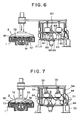
- the upper platen 2 descends toward the lower platen 1, so, as shown in FIG. 6, when the upper plate 2 descends to a position directly above and in close proximity to the workpiece W, the cylinder 60 and the motor 65 stop being driven and the upper platen 2 is maintained at the position directly above and in close proximity to the workpiece W.
- the air pump 72 is used to draw the air out of the air bags 70 to make the air bags 70 contract, whereupon the upper platen 2 gradually descends toward the workpiece W and contacts the surface of the workpiece W.
- the above contact work is performed by the sub cylinder 202, but due to the variation in the sliding frictional resistance between the piston 204 and the cylinder body 203, the piston 204 does not move in accordance with the change in pressure in the cylinder body 203 and sometimes the upper platen 120 falls rapidly on the workpiece W.
- the upper platen 2 descends continuously in accordance with the amount of contraction of the air bags 70.
- the rate of contraction of the air bags 70 By making the rate of contraction of the air bags 70 smaller, it is possible to make the upper platen 2 come into soft contact with the surface of the workpiece W.
- the air bags 70 further contract gradually after the upper platen 2 comes into contact with the workpiece W, the pressing force of the upper platen 2 on the workpiece W increases continuously, so the air pump 72 is stopped when the desired pressing force is reached.
- FIG. 8 is a partially cutaway front view of a two-sided flattening apparatus according to a second embodiment of the present invention.
- the two-sided flattening apparatus of this embodiment differs from the first embodiment in the point of arranging the elevator mechanism 3 above the lower platen 1.
- the elevator mechanism 3 as a whole is attached above the lower platen 1 in an upside-down state.
- the connecting member 4' is connected to the lower ends of the three air bags 70 through the shafts 73. Therefore, the top ends of the air bags 70 are connected to the lower ends of the piston rods 61 of the cylinders 60 through the movable plate 63.
- the upper platen 2 is connected rotatably to the support mechanism 40' attached to the center portion of the connecting member 4'. That is, the shaft 22 is inserted through the support member 40' and a bearing 41 is attached between the shaft 22 and the support member 40'.
- the air pump 72 is used to drawn the air out from the three air bags 70 to make the air bags 70 contract. Further, the three cylinders 60 of the main elevator 6 are drive in reverse to retract the piston rods 61 equally and the motor 65 is driven in reverse so that the female screw member 68 of the movable plate 63 rises along the male screw member 67.
- the cylinders 60 are driven to make the piston rods 61 extend and the motor 65 is driven so that the female screw member 68 of the movable plate 63 descends along the male screw member 67.
- the air pump 72 is used to supply air into the air bags 70 to make the air bags 70 gradually expand. Further, by making the air bags 70 gradually expand, it is possible to make the pressing force of the upper platen 2 on the workpiece W a desired pressing force.
- a motor 65 was provided, but it is possible to leave this out and make the upper platen 2 rise or descend by just the three cylinders 60.
- the invention was configured to make the three air bags 70 expand and contract by pumping in or out air, but the invention may also be configured to make the air bags 70 expand and contract by filling air into the air bags 70 in advance and then heating or cooling the air in the air bags 70 by a heating/cooling apparatus.
- the main elevator of the elevator mechanism is used to make the upper platen descend to close to the workpiece on the top of the lower platen, then the sub elevator of the elevator mechanism is used to make the upper platen continuously descend toward the workpiece. Therefore, there are the superior effects that it is possible to bring even a heavy upper platen into soft contact with a workpiece and possible to prevent damage to the workpiece at the time of contact with the upper platen.
Landscapes
- Engineering & Computer Science (AREA)
- Mechanical Engineering (AREA)
- Finish Polishing, Edge Sharpening, And Grinding By Specific Grinding Devices (AREA)
- Constituent Portions Of Griding Lathes, Driving, Sensing And Control (AREA)
- Mechanical Treatment Of Semiconductor (AREA)
Applications Claiming Priority (2)
| Application Number | Priority Date | Filing Date | Title |
|---|---|---|---|
| JP17492698 | 1998-06-22 | ||
| JP17492698A JP2000006005A (ja) | 1998-06-22 | 1998-06-22 | 両面研磨装置 |
Publications (1)
| Publication Number | Publication Date |
|---|---|
| EP0967048A1 true EP0967048A1 (fr) | 1999-12-29 |
Family
ID=15987142
Family Applications (1)
| Application Number | Title | Priority Date | Filing Date |
|---|---|---|---|
| EP99110960A Withdrawn EP0967048A1 (fr) | 1998-06-22 | 1999-06-08 | Appareil de polissage double face |
Country Status (2)
| Country | Link |
|---|---|
| EP (1) | EP0967048A1 (fr) |
| JP (1) | JP2000006005A (fr) |
Cited By (7)
| Publication number | Priority date | Publication date | Assignee | Title |
|---|---|---|---|---|
| CN112171392A (zh) * | 2020-09-30 | 2021-01-05 | 广东鼎泰机器人科技有限公司 | 一种带有压持结构的多方位刀具磨削机构 |
| CN116372695A (zh) * | 2023-04-04 | 2023-07-04 | 江苏盛安传动股份公司 | 一种齿轮加工用齿轮端面磨平装置 |
| US11801580B1 (en) | 2019-12-16 | 2023-10-31 | Arc Specialties, Inc. | Dual airbag compliance device for ball and seat lapping |
| CN117086774A (zh) * | 2023-10-19 | 2023-11-21 | 新乡市斯凯夫机械有限公司 | 一种陶瓷件专用研磨机及研磨工艺 |
| CN118219119A (zh) * | 2024-04-17 | 2024-06-21 | 东台启盛新能源科技有限公司 | 一种方便取出的风扇叶片打磨机及使用方法 |
| CN119304708A (zh) * | 2024-03-15 | 2025-01-14 | 新泰市东晟机械有限公司 | 具有夹持功能的轴承室生产抛光装置 |
| CN119319504A (zh) * | 2024-10-18 | 2025-01-17 | 郑州大学 | 一种修复加固混凝土构件表面处理装置 |
Families Citing this family (2)
| Publication number | Priority date | Publication date | Assignee | Title |
|---|---|---|---|---|
| CN111940243B (zh) * | 2020-06-30 | 2021-10-19 | 蒙特费罗(湖州)电梯部件有限公司 | 一种电梯轿厢生产用防腐处理装置 |
| JP2023094699A (ja) * | 2021-12-24 | 2023-07-06 | 株式会社ディスコ | 治具、装着方法及び取り外し方法 |
Citations (5)
| Publication number | Priority date | Publication date | Assignee | Title |
|---|---|---|---|---|
| US4370835A (en) * | 1979-12-18 | 1983-02-01 | Peter Wolters | Working pressure control mechanism |
| EP0481936A2 (fr) * | 1990-10-17 | 1992-04-22 | MELCHIORRE OFFICINA MECCANICA S.r.l. | Méthode et appareil pour le contrôle continu de la pression d'application sur une pièce dans une machine à roder des deux côtés |
| EP0747167A2 (fr) * | 1995-06-09 | 1996-12-11 | Applied Materials, Inc. | Appareil pour retenir une plaquette pendant le polissage |
| US5681215A (en) * | 1995-10-27 | 1997-10-28 | Applied Materials, Inc. | Carrier head design for a chemical mechanical polishing apparatus |
| EP0847835A1 (fr) * | 1996-12-12 | 1998-06-17 | Wacker Siltronic Gesellschaft für Halbleitermaterialien Aktiengesellschaft | Procédé et dispositif pour le polissage des plaquettes semiconductrices |
-
1998
- 1998-06-22 JP JP17492698A patent/JP2000006005A/ja active Pending
-
1999
- 1999-06-08 EP EP99110960A patent/EP0967048A1/fr not_active Withdrawn
Patent Citations (5)
| Publication number | Priority date | Publication date | Assignee | Title |
|---|---|---|---|---|
| US4370835A (en) * | 1979-12-18 | 1983-02-01 | Peter Wolters | Working pressure control mechanism |
| EP0481936A2 (fr) * | 1990-10-17 | 1992-04-22 | MELCHIORRE OFFICINA MECCANICA S.r.l. | Méthode et appareil pour le contrôle continu de la pression d'application sur une pièce dans une machine à roder des deux côtés |
| EP0747167A2 (fr) * | 1995-06-09 | 1996-12-11 | Applied Materials, Inc. | Appareil pour retenir une plaquette pendant le polissage |
| US5681215A (en) * | 1995-10-27 | 1997-10-28 | Applied Materials, Inc. | Carrier head design for a chemical mechanical polishing apparatus |
| EP0847835A1 (fr) * | 1996-12-12 | 1998-06-17 | Wacker Siltronic Gesellschaft für Halbleitermaterialien Aktiengesellschaft | Procédé et dispositif pour le polissage des plaquettes semiconductrices |
Cited By (9)
| Publication number | Priority date | Publication date | Assignee | Title |
|---|---|---|---|---|
| US11801580B1 (en) | 2019-12-16 | 2023-10-31 | Arc Specialties, Inc. | Dual airbag compliance device for ball and seat lapping |
| CN112171392A (zh) * | 2020-09-30 | 2021-01-05 | 广东鼎泰机器人科技有限公司 | 一种带有压持结构的多方位刀具磨削机构 |
| CN116372695A (zh) * | 2023-04-04 | 2023-07-04 | 江苏盛安传动股份公司 | 一种齿轮加工用齿轮端面磨平装置 |
| CN116372695B (zh) * | 2023-04-04 | 2023-09-29 | 江苏盛安传动股份公司 | 一种齿轮加工用齿轮端面磨平装置 |
| CN117086774A (zh) * | 2023-10-19 | 2023-11-21 | 新乡市斯凯夫机械有限公司 | 一种陶瓷件专用研磨机及研磨工艺 |
| CN117086774B (zh) * | 2023-10-19 | 2024-01-05 | 新乡市斯凯夫机械有限公司 | 一种陶瓷件专用研磨机及研磨工艺 |
| CN119304708A (zh) * | 2024-03-15 | 2025-01-14 | 新泰市东晟机械有限公司 | 具有夹持功能的轴承室生产抛光装置 |
| CN118219119A (zh) * | 2024-04-17 | 2024-06-21 | 东台启盛新能源科技有限公司 | 一种方便取出的风扇叶片打磨机及使用方法 |
| CN119319504A (zh) * | 2024-10-18 | 2025-01-17 | 郑州大学 | 一种修复加固混凝土构件表面处理装置 |
Also Published As
| Publication number | Publication date |
|---|---|
| JP2000006005A (ja) | 2000-01-11 |
Similar Documents
| Publication | Publication Date | Title |
|---|---|---|
| KR19990082691A (ko) | 유리물품의가공마무리장치 | |
| KR20010015582A (ko) | 3지주에 장착된 플래폼 조립체가 설치된 연마기 | |
| CN110270898B (zh) | 一种凸度圆柱滚子外圆的柔性超精研抛加工装置及方法 | |
| CN100472074C (zh) | 线性致动器及其处理方法 | |
| JPH1052825A (ja) | タイヤ加硫機 | |
| CN119427084A (zh) | 一种轴承外圈的内外自动打磨机床 | |
| CN120680371B (zh) | 一种偏心磨削加工装置 | |
| KR101986907B1 (ko) | 구면 연마장치 | |
| CN113618595A (zh) | 一种抛光盘平面度可调整抛光装置及其工作方法 | |
| CN114193320B (zh) | 旋转装夹机构 | |
| CN216707107U (zh) | 一种研磨超精机 | |
| CN217019903U (zh) | 一种用于高承载力双金属轴承内孔抛光的工装 | |
| JP2000006005A (ja) | 両面研磨装置 | |
| CN120480694A (zh) | 一种模具加工用孔壁打磨设备 | |
| CN113560994A (zh) | 一种光学镜片加工用抛光连续化加工装置 | |
| CN117921500B (zh) | 一种铸件多角度打磨装置 | |
| CN219967522U (zh) | 一种钢材表面抛光装置 | |
| JP3673904B2 (ja) | 薄板円板状ワークの両面研削装置 | |
| CN109759905B (zh) | 一种磁流变抛光加工系统 | |
| JP4285888B2 (ja) | 揺動式両面研磨装置 | |
| CN210586520U (zh) | 一种用于弯板成型的压型模 | |
| CN216127023U (zh) | 一种用于加工止回阀的抛光机 | |
| CN114406817A (zh) | 一种偏心孔定位装置 | |
| CN112192398A (zh) | 一种便携式倒角设备 | |
| US6227945B1 (en) | Method and apparatus for polishing the outer periphery of disc-shaped workpiece |
Legal Events
| Date | Code | Title | Description |
|---|---|---|---|
| PUAI | Public reference made under article 153(3) epc to a published international application that has entered the european phase |
Free format text: ORIGINAL CODE: 0009012 |
|
| 17P | Request for examination filed |
Effective date: 19991025 |
|
| AK | Designated contracting states |
Kind code of ref document: A1 Designated state(s): DE FR GB NL |
|
| AX | Request for extension of the european patent |
Free format text: AL;LT;LV;MK;RO;SI |
|
| 17Q | First examination report despatched |
Effective date: 20000623 |
|
| AKX | Designation fees paid |
Free format text: DE FR GB NL |
|
| RBV | Designated contracting states (corrected) |
Designated state(s): DE FR GB NL |
|
| STAA | Information on the status of an ep patent application or granted ep patent |
Free format text: STATUS: THE APPLICATION IS DEEMED TO BE WITHDRAWN |
|
| 18D | Application deemed to be withdrawn |
Effective date: 20001104 |