EP0967104A2 - Apparatus with directable blades for conveying air to radiators of motor vehicles and the like - Google Patents
Apparatus with directable blades for conveying air to radiators of motor vehicles and the like Download PDFInfo
- Publication number
- EP0967104A2 EP0967104A2 EP99201818A EP99201818A EP0967104A2 EP 0967104 A2 EP0967104 A2 EP 0967104A2 EP 99201818 A EP99201818 A EP 99201818A EP 99201818 A EP99201818 A EP 99201818A EP 0967104 A2 EP0967104 A2 EP 0967104A2
- Authority
- EP
- European Patent Office
- Prior art keywords
- blades
- transmission
- rotation
- pivot pin
- gearing
- Prior art date
- Legal status (The legal status is an assumption and is not a legal conclusion. Google has not performed a legal analysis and makes no representation as to the accuracy of the status listed.)
- Withdrawn
Links
Images


Classifications
-
- F—MECHANICAL ENGINEERING; LIGHTING; HEATING; WEAPONS; BLASTING
- F01—MACHINES OR ENGINES IN GENERAL; ENGINE PLANTS IN GENERAL; STEAM ENGINES
- F01P—COOLING OF MACHINES OR ENGINES IN GENERAL; COOLING OF INTERNAL-COMBUSTION ENGINES
- F01P7/00—Controlling of coolant flow
- F01P7/02—Controlling of coolant flow the coolant being cooling-air
- F01P7/06—Controlling of coolant flow the coolant being cooling-air by varying blade pitch
-
- B—PERFORMING OPERATIONS; TRANSPORTING
- B60—VEHICLES IN GENERAL
- B60K—ARRANGEMENT OR MOUNTING OF PROPULSION UNITS OR OF TRANSMISSIONS IN VEHICLES; ARRANGEMENT OR MOUNTING OF PLURAL DIVERSE PRIME-MOVERS IN VEHICLES; AUXILIARY DRIVES FOR VEHICLES; INSTRUMENTATION OR DASHBOARDS FOR VEHICLES; ARRANGEMENTS IN CONNECTION WITH COOLING, AIR INTAKE, GAS EXHAUST OR FUEL SUPPLY OF PROPULSION UNITS IN VEHICLES
- B60K11/00—Arrangement in connection with cooling of propulsion units
- B60K11/02—Arrangement in connection with cooling of propulsion units with liquid cooling
- B60K11/04—Arrangement or mounting of radiators, radiator shutters, or radiator blinds
Definitions
- the present invention relates to an apparatus which comprises a fan with directable blades for conveying air to radiators of motor vehicles and the like and is able to perform adjustment of the quantity of air conveyed onto the heat exchanger containing the cooling liquid so as to keep the engine at the most suitable temperature in all operating conditions thereof.
- said apparatus must be operated only when a certain predefined temperature of the water is reached, said temperature being detected by means of a thermostat which actuates suitable engaging devices - such as, for example, an electromagnetic clutch, closing of which causes the rotational movement of the fan - which are designed to cause rotation of the fan itself at varying speeds so as to regulate the flowrate of the cooling air forced onto the radiator in accordance with the real needs arising from the conditions which produce the increase in temperature.
- suitable engaging devices - such as, for example, an electromagnetic clutch, closing of which causes the rotational movement of the fan - which are designed to cause rotation of the fan itself at varying speeds so as to regulate the flowrate of the cooling air forced onto the radiator in accordance with the real needs arising from the conditions which produce the increase in temperature.
- said apparatus do not allow continuous adjustment of the quantity of air forced onto the heat exchanger which cools the liquid, thus limiting the potential performance of the device.
- the technical problem which is posed, therefore, is that of providing a ventilation apparatus for conveying the air cooling the cooling liquid in motor vehicles or the like, which allows the flowrate of the air forced onto the heat exchanger containing the cooling liquid to be continuously adjusted, without the need for variation in the speed of rotation of the fan which is able to run at a constant speed which is substantially the same as, or proportional to, the speed of rotation of the actuating shaft connected to the driving shaft, without the need for devices controlling the speed itself.
- the quantity of air forced onto the heat exchanger should be controlled by means of the direct detection of the temperature of the cooling liquid depending on the different or particular external climatic conditions due to the very high or very low temperatures of the environment itself.
- an apparatus for conveying air to radiators of vehicles and the like comprising a central body mounted on a rotating support and a plurality of blades radially mounted by means of associated engaging elements on said central body, in which said blades are rotatable about their respective longitudinal axis upon actuation of associated drive means and transmission means for the movement, forming part of the apparatus itself.
- the apparatus 10 for cooling the cooling liquid in motor vehicles and the like according to the invention is mounted on a device 20 for supporting and transmitting the movement, comprising a support 21 rotating with respect to a fixture 22 joined to the body 22a of the engine by means of bolts 22b or the like and extending in the longitudinal direction with a shaft 21a on which the apparatus 10 is mounted.
- the support 21, and hence the apparatus 10 are kept constantly rotating by means of a pulley 23 which is joined to the support itself and connected in a known manner to a shaft of the vehicle engine.
- the apparatus 10 essentially consists of a central body 11 on which the blades 12 are radially mounted, said blades causing the flow of the air from the outside towards the radiator (not shown) containing the cooling liquid.
- each blade 12 situated inside the central body 11 consists of a pivot pin 31 which has a cylindrical toothing 31a and is radially mounted by means of bearings 31b on the body 11.
- each blade 12 in addition to rotating with the fan 10 on the support 21a, is also able to rotate about its own longitudinal axis 12a as will emerge more clearly below.
- Each gearing 31a is in fact coupled to an actuating device consisting of an associated rectilinear rack 41a which is integral with a tube 41 mounted on the shaft 21a with which it therefore rotates integrally.
- the tube 41 is also connected, by means of a bearing 42a, to a disk 42 which may be translated parallel to the shaft 21a by means of a screw 43a operated by a motor 43 arranged outside the support 21.
- the blade actuation device allows all the blades to be rotated simultaneously and in the same manner through a certain angle which is determined in each case according to needs.
- the external motor may in fact be controlled in a known manner so as to obtain a substantially continuous variation in the angle of orientation of the blades.
- Fig. 3 shows a first variation of an example of embodiment of the device 140 for actuating rotation of the blades 12.
- the motor 43 is arranged inside the support 121 of the fan.
- Said support is in this case formed by two bell-shaped members 121a and 121b located opposite each other and separated by a partition 121c carrying the shank 141b of a disk 141 on which the racks 141a are mounted.
- said shank 141b extends on the opposite side to that of the racks 141a and is integral, by means of bearings 141c, with a further element 142 axially movable translationwise upon operation of a screw 43a which can be actuated by means of a motor 43, which are coaxially arranged inside the support 121.
- Rotation of the element 142 is prevented by the longitudinal pin 142a.
- Figure 4 shows a further embodiment of the apparatus according to the invention, in which the motor 43 is replaced by a double-acting cylinder 143 which is in turn arranged inside the support 121 and the rod 143a of which is connected to the element 142.
- Figs. 5a and 5b show a further embodiment of the device for actuating rotation of the blades about their longitudinal axes.
- each pivot pin 231 of the blade 12 has a bevel gearing 230 and one of said pivot pins 231 extends longitudinally towards the centre of the fan where it has a cylindrical toothing 231a designed to co-operate with a rack 241a which has a shank 241b.
- the shank 241b is radially connected, by means of a pin 244a which passes through the support 221, via an eyelet 221c, to a bush 244 which is in turn coupled by means of bearing 42a to a disk 42 which can be translated by means of the screw 43a and the motor 43 which are located outside the support 221.
- the bevel gears 230 of the blades are engaged with bevel gears 230a which form a chain for transmission of the rotation to all the blades 12 with the same direction of rotation being maintained for all the blades themselves which are thus oriented simultaneously and in the same manner as required.
- the fan according to the invention may have a device for actuating rotation of the blades, realized in accordance with a further variation.
- each blade 12 has a bevel gearing 331a on its pivot pin 331; each bevel gearing 331a meshes with a bevel wheel 341a which has a tube 341b extending on the opposite side to the toothing and mounted on the same shaft 321a supporting the fan 11.
- Said tube 341b has, in a suitable position, an eyelet 341c with its axis inclined with respect to the axis of the shaft 321a.
- the tube 341b is radially connected, by means of a pin 344a inserted inside the eyelet 341c, to a bush 344 which is in turn coupled, by means of a bearing 42a, to a disk 42 which can be translated by means of the screw 43a and the motor 43 which are located outside the support 321.
- Fig. 9 shows a drive device consisting of a double-acting cylinder 143 arranged inside the support 121 of the fan in a similar manner to that illustrated in Figs. 4 and 7.
- the rod 143a of the cylinder actuates a cup-shaped member 343a which has a pin 344a radially projecting inwards and inserted into the eyelet 341c of the tube 341b. In this case also the forwards movement of the rod 143a causes rotation of the bevel wheel 341a.
- the drive system may consist of a motor 43 which is arranged inside the support 321 of the fan 10.
- Fig. 10a shows a further variation of an example of the device for rotational actuation of the blades 12 which are mounted in the body 11 of the fan by means of a smooth pivot pin 431 which is axially keyed into a first hole 431b formed at a first end of an associated lever 431a, the other end of which has a second hole 431c which receives a pivot pin 441a radially integral with a plate 441 mounted, by means of a bearing 441d, on a support 441b which is radially connected, by means of a pin 444a, to bush 44 which is in turn coupled, by means of the bearing 42a, to the disk 42 which can be translated by means of the screw 43a and the motor 43 which are located outside the support 421 of the fan.
- the forwards movement/backwards movement of the disk 42 upon operation of the motor 43, causes the forwards movement/backwards movement and simultaneous rotation of the plate 441 and the consequent rotation of the levers 431a which cause the simultaneous and uniform rotation of the blades 12.
- a drive device located inside the support 421 of the fan shown, by way of example in Fig. 11, as a cylinder 143, the rod 143a of which directly causes the translation - and therefore the rotation owing to the constraints imposed - of the plate 451.
- the drive system for rotation located inside the fan support, may consist of an electric motor or the like.
- Figure 12 shows a further example of embodiment of the device for rotational actuation of the blades 12 about their longitudinal axis 12a.
- each blade 12 is mounted in the body 11 of the fan by means of its pivot pin 531 joined to a first end of an L-shaped lever 531a, the other end of which is connected to a disk 541 by means of a radial pin 541a.
- Said disk 541 is in turn coupled, by means of a bearing 541d, to an axial extension 541b designed for engagement with an actuating device 540.
- Said axial extension 541b comprises a bell member 551 with an internal thread 551a designed to engage with a threading 552a of a shaft 552 which is in turn integral with a double-acting hydraulic actuator 543, the piston 543a of which may be rotationally actuated in either direction by means of suitable supplying/discharging of corresponding fluid recirculation ducts 543b respectively leading into the two chambers 543c of the cylinder 543.
- the shaft 552 extends over a short distance outside the cylinder 543 on the opposite side to the fan so as to allow coupling to a device 544 for measuring the rotation performed by the piston 543a.
- This device may for example consist of an encoder which is conventional per se and therefore not described in detail.
- the operating principle of the apparatus is as follows: When manual operation or automatic control produces supplying/discharging of either of the two ducts 543b, the piston 543a rotates in one direction (Fig. 13a) or the other direction (Fig. 13c) causing rotation of the shaft 552 in either direction so that the threading 552a, acting on the internal thread 551a of the bell member 551, produces translation thereof in either direction, causing the forwards movement/backwards movement of the disk 541 which, acting by means of the levers 531a, on each pivot pin 531 of the blades 12, causes the controlled rotation of the latter about their longitudinal axes 12a in one direction (Fig. 13b) or in the other direction (Fig. 13d).
- Fig. 14 shows solely the detail of a variation of embodiment of the devices for controlling rotation which in this case are formed by means of sensors 1544 which are arranged outside the bell member 551. With this configuration it is obviously possible to obtain stepwise control of the position and not continuous control as in the case above.
- Fig. 14 also shows means 600 which are designed make rotation of the shaft 552 and hence the blades 12 irreversible.
- Said means 600 consist of an electromagnet 601 acting on a pin 602 designed to engage with a corresponding seat 603 of the shaft 552, once controlled rotation of the latter has terminated.
- detection means such as sensors and the like which can be associated with programming devices designed to automate adjustment of the angle of rotation of the blades.
Landscapes
- Engineering & Computer Science (AREA)
- Chemical & Material Sciences (AREA)
- Combustion & Propulsion (AREA)
- Mechanical Engineering (AREA)
- General Engineering & Computer Science (AREA)
- Structures Of Non-Positive Displacement Pumps (AREA)
- Devices For Post-Treatments, Processing, Supply, Discharge, And Other Processes (AREA)
Abstract
Description
- The present invention relates to an apparatus which comprises a fan with directable blades for conveying air to radiators of motor vehicles and the like and is able to perform adjustment of the quantity of air conveyed onto the heat exchanger containing the cooling liquid so as to keep the engine at the most suitable temperature in all operating conditions thereof.
- In the technical sector relating to the treatment of cooling liquids contained in the radiators of motor vehicles or the like it is known that there is the need to force a flow of air onto the radiator itself in order to obtain a more rapid dissipation of heat from the liquid to the exterior, said forced air flow being obtained by causing rotation of an apparatus which is normally mounted either directly on the driving shaft or on the shaft of the water pump or on a driven shaft carrying a pulley which receives movement from a belt actuated by the driving shaft itself.
- It is also known that said apparatus must be operated only when a certain predefined temperature of the water is reached, said temperature being detected by means of a thermostat which actuates suitable engaging devices - such as, for example, an electromagnetic clutch, closing of which causes the rotational movement of the fan - which are designed to cause rotation of the fan itself at varying speeds so as to regulate the flowrate of the cooling air forced onto the radiator in accordance with the real needs arising from the conditions which produce the increase in temperature.
- An example of such adjustments to the speed of rotation of the fan is illustrated in IT-MI97A 1447 in the name of the same present Applicants.
- Although performing their function, said apparatus do not allow continuous adjustment of the quantity of air forced onto the heat exchanger which cools the liquid, thus limiting the potential performance of the device.
- The technical problem which is posed, therefore, is that of providing a ventilation apparatus for conveying the air cooling the cooling liquid in motor vehicles or the like, which allows the flowrate of the air forced onto the heat exchanger containing the cooling liquid to be continuously adjusted, without the need for variation in the speed of rotation of the fan which is able to run at a constant speed which is substantially the same as, or proportional to, the speed of rotation of the actuating shaft connected to the driving shaft, without the need for devices controlling the speed itself.
- Within the scope of this problem a further requirement is that the quantity of air forced onto the heat exchanger should be controlled by means of the direct detection of the temperature of the cooling liquid depending on the different or particular external climatic conditions due to the very high or very low temperatures of the environment itself.
- These technical problems are solved according to the present invention by an apparatus for conveying air to radiators of vehicles and the like, comprising a central body mounted on a rotating support and a plurality of blades radially mounted by means of associated engaging elements on said central body, in which said blades are rotatable about their respective longitudinal axis upon actuation of associated drive means and transmission means for the movement, forming part of the apparatus itself.
- Further details may be obtained from the following description of a non-limiting example of embodiment of the invention provided with reference to the accompanying drawings in which:
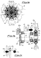
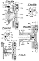
- Figure 1a shows a cross-section transverse to the axis of the apparatus according to the present invention with a device for orientation of the blades of the multiple rack type and associated drive system outside the fan support;
- Figure 1b shows a cross-section along the plane indicated by Ib-Ib in Fig. 1a;
- Figure 1c shows a simplified diagram of the device for performing rotation of the blades, corresponding to Fig. 1b;
- Figure 2a shows a schematic cross-section transverse to the axis of the fan apparatus according to the present invention with a rack-type device for orientation of the blades, in the minimum air flow position;
- Figure 2b shows a cross-section along the plane indicated by IIb-IIb in Fig. 2a;
- Figure 2c shows a simplified diagram of the device for actuating rotation of the blades, corresponding to Fig. 2b;
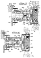
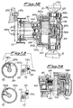
- Figure 3 shows a cross-sectional view, similar to that of Fig. 2b, of the apparatus according to the invention with a device for actuation of the blades and associated drive system inside the fan support;
- Figure 4 shows a cross-sectional view, similar to that of Fig. 3, of a different actuation drive system inside the apparatus support;
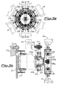
- Figure 5a shows a cross-sectional view, similar to that of Fig. 1a, of the apparatus according to the invention with a device for actuation of the blades of the centralized rack type and associated drive system outside the apparatus support;
- Figure 5b shows a cross-section along the plane Vb-Vb of Fig. 5a;
- Figure 6 shows an axial cross-section through the apparatus of the centralized rack type with a device for actuation of the blades and associated drive system inside the fan support;
- Figure 7 shows a cross-sectional view, similar to that of Fig. 6, with a different realization of the drive system for actuation of the blades inside the driving shaft;
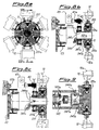
- Figure 8a shows a cross-sectional view, similar to that of Fig. 1a, of a further embodiment of the apparatus according to the invention with a device for moving the blades of the bevel wheel type and associated drive system outside the fan support;
- Figure 8b shows a cross-section along the plane indicated by VIIIb-VIIIb in Fig. 8a with the blades in the maximum flow position;
- Figure 8c shows a cross-section along the plane indicated by VIIIb-VIIIb in Fig. 8a with the blades in the minimum flow position;
- Figure 9 shows a cross-section, similar to that of Fig. 8b, with a device for actuation of the blades and associated drive system which are located inside the shaft supporting the fan;
- Figure 10a shows a cross-sectional view, along an axial vertical plane, of a further embodiment of the apparatus with a device for actuation of the blades of the lever type and drive system outside the fan support with the blades in the maximum flow position;
- Figure 10b shows a schematic view of the blade actuating lever according to Fig. 10a;
- Figure 10c shows a cross-section, similar to that of Fig. 10a, with the blades in the minimum flow position;
- Figure 10d is a schematic view of the blade actuating lever according to Fig. 10c;
- Figure 11 shows a cross-section, similar to that of Fig. 10a, with a device for actuation of the blades and associated drive system which are located inside the fan support;
- Figure 12 shows a further variation of an embodiment of the apparatus according to the invention;
- Figures 13a to 13d show a detail of the different positions of the means for actuation of blades; and
- Figure 14 shows an example of a variation of the devices for controlling the position of the blade during rotation about its longitudinal axis and the means for irreversibility of rotation itself.
- As shown in Figs. 1a, 1b, the
apparatus 10 for cooling the cooling liquid in motor vehicles and the like according to the invention is mounted on adevice 20 for supporting and transmitting the movement, comprising asupport 21 rotating with respect to afixture 22 joined to thebody 22a of the engine by means of bolts 22b or the like and extending in the longitudinal direction with ashaft 21a on which theapparatus 10 is mounted. Thesupport 21, and hence theapparatus 10, are kept constantly rotating by means of apulley 23 which is joined to the support itself and connected in a known manner to a shaft of the vehicle engine. - The
apparatus 10 essentially consists of acentral body 11 on which theblades 12 are radially mounted, said blades causing the flow of the air from the outside towards the radiator (not shown) containing the cooling liquid. - In the example of embodiment according to Fig. 1a, the end of each
blade 12 situated inside thecentral body 11 consists of apivot pin 31 which has acylindrical toothing 31a and is radially mounted by means ofbearings 31b on thebody 11. In this way eachblade 12, in addition to rotating with thefan 10 on thesupport 21a, is also able to rotate about its ownlongitudinal axis 12a as will emerge more clearly below. - Each
gearing 31a is in fact coupled to an actuating device consisting of an associatedrectilinear rack 41a which is integral with atube 41 mounted on theshaft 21a with which it therefore rotates integrally. - The
tube 41 is also connected, by means of abearing 42a, to adisk 42 which may be translated parallel to theshaft 21a by means of ascrew 43a operated by amotor 43 arranged outside thesupport 21. - In this way it is possible, during rotation of the fan, to actuate, as required, the
motor 43 which moves (in either direction) thedisk 42 which, moving backwards towards the support 21 (Figs. 1b and 1c) or moving forwards towards the fan (Figs. 2b and 2c), causes respectively the backwards movement/forwards movement of therack 41a and hence the rotation, in either direction, of thegearing 31a with consequent rotation of theblades 12 from a maximum flow position (Fig. 1b) to a minimum flow position (Fig. 2b). - As is obvious, the blade actuation device allows all the blades to be rotated simultaneously and in the same manner through a certain angle which is determined in each case according to needs.
- The external motor may in fact be controlled in a known manner so as to obtain a substantially continuous variation in the angle of orientation of the blades.
- Fig. 3 shows a first variation of an example of embodiment of the device 140 for actuating rotation of the
blades 12. In this configuration themotor 43 is arranged inside thesupport 121 of the fan. - Said support is in this case formed by two bell-shaped members 121a and 121b located opposite each other and separated by a
partition 121c carrying theshank 141b of adisk 141 on which theracks 141a are mounted. In greater detail, saidshank 141b extends on the opposite side to that of theracks 141a and is integral, by means ofbearings 141c, with afurther element 142 axially movable translationwise upon operation of ascrew 43a which can be actuated by means of amotor 43, which are coaxially arranged inside thesupport 121. - Rotation of the
element 142 is prevented by thelongitudinal pin 142a. - Figure 4 shows a further embodiment of the apparatus according to the invention, in which the
motor 43 is replaced by a double-actingcylinder 143 which is in turn arranged inside thesupport 121 and therod 143a of which is connected to theelement 142. - Figs. 5a and 5b show a further embodiment of the device for actuating rotation of the blades about their longitudinal axes.
- In this configuration each
pivot pin 231 of theblade 12 has abevel gearing 230 and one of said pivot pins 231 extends longitudinally towards the centre of the fan where it has acylindrical toothing 231a designed to co-operate with arack 241a which has ashank 241b. - The
shank 241b is radially connected, by means of apin 244a which passes through thesupport 221, via aneyelet 221c, to a bush 244 which is in turn coupled by means of bearing 42a to adisk 42 which can be translated by means of thescrew 43a and themotor 43 which are located outside thesupport 221. - In this way actuation of the
motor 43 causes the forwards movement of thedisk 42 and hence thepin 244a inside the associatedeyelet 221c; the forwards movement of thepin 244a causes the consequent forwards movement of theshank 241b which moves, together with it, thecentral rack 241a which in turn actuates thegearing 231a, thepivot pin 231 and thebevel gearing 230. - As shown in Fig. 5a, the
bevel gears 230 of the blades are engaged withbevel gears 230a which form a chain for transmission of the rotation to all theblades 12 with the same direction of rotation being maintained for all the blades themselves which are thus oriented simultaneously and in the same manner as required. - In this case also it is possible to envisage (Figs. 6 and 7) the arrangement of the
drive system rack 241a in a position inside thesupport 121 of the fan. Since the design of the various parts is substantially the same as that already described in connection with Figs. 3 and 4, respectively, a further description of the corresponding Figs. 6 and 7 will not provided, since the correspondence with the said preceding figures may be easily verified. - As illustrated in Figs. 8a to 8c, the fan according to the invention may have a device for actuating rotation of the blades, realized in accordance with a further variation.
- In this configuration each
blade 12 has abevel gearing 331a on itspivot pin 331; eachbevel gearing 331a meshes with abevel wheel 341a which has atube 341b extending on the opposite side to the toothing and mounted on thesame shaft 321a supporting thefan 11. -
Said tube 341b has, in a suitable position, aneyelet 341c with its axis inclined with respect to the axis of theshaft 321a. - The
tube 341b is radially connected, by means of apin 344a inserted inside theeyelet 341c, to abush 344 which is in turn coupled, by means of abearing 42a, to adisk 42 which can be translated by means of thescrew 43a and themotor 43 which are located outside the support 321. - In this way, when the
motor 43 actuates thescrew 43a and causes the axial displacement of thedisk 42 in either direction, this also produces the movement, along with it, of thebush 344 which is connected to theshaft 321a by means of thepin 344a and, as a result of the action of the latter on theinclined eyelet 341c, a corresponding rotation of thebevel wheel 341a which causes the rotation, simultaneously and in the same manner, of all the bevel gears 330 with consequent rotation of theblades 12. - Fig. 9 shows a drive device consisting of a double-acting
cylinder 143 arranged inside thesupport 121 of the fan in a similar manner to that illustrated in Figs. 4 and 7. - The
rod 143a of the cylinder actuates a cup-shapedmember 343a which has apin 344a radially projecting inwards and inserted into theeyelet 341c of thetube 341b. In this case also the forwards movement of therod 143a causes rotation of thebevel wheel 341a. - In this version also, the drive system may consist of a
motor 43 which is arranged inside the support 321 of thefan 10. - Fig. 10a shows a further variation of an example of the device for rotational actuation of the
blades 12 which are mounted in thebody 11 of the fan by means of asmooth pivot pin 431 which is axially keyed into afirst hole 431b formed at a first end of an associatedlever 431a, the other end of which has asecond hole 431c which receives apivot pin 441a radially integral with aplate 441 mounted, by means of abearing 441d, on asupport 441b which is radially connected, by means of apin 444a, tobush 44 which is in turn coupled, by means of thebearing 42a, to thedisk 42 which can be translated by means of thescrew 43a and themotor 43 which are located outside thesupport 421 of the fan. - The forwards movement/backwards movement of the
disk 42, upon operation of themotor 43, causes the forwards movement/backwards movement and simultaneous rotation of theplate 441 and the consequent rotation of thelevers 431a which cause the simultaneous and uniform rotation of theblades 12. - For this embodiment also it is possible to envisage a drive device located inside the
support 421 of the fan shown, by way of example in Fig. 11, as acylinder 143, therod 143a of which directly causes the translation - and therefore the rotation owing to the constraints imposed - of theplate 451. - In a manner similar to that of the preceding examples, the drive system for rotation, located inside the fan support, may consist of an electric motor or the like.
- Figure 12 shows a further example of embodiment of the device for rotational actuation of the
blades 12 about theirlongitudinal axis 12a. - In this configuration, each
blade 12 is mounted in thebody 11 of the fan by means of itspivot pin 531 joined to a first end of an L-shapedlever 531a, the other end of which is connected to adisk 541 by means of aradial pin 541a. -
Said disk 541 is in turn coupled, by means of a bearing 541d, to an axial extension 541b designed for engagement with anactuating device 540. - Said axial extension 541b comprises a
bell member 551 with an internal thread 551a designed to engage with a threading 552a of ashaft 552 which is in turn integral with a double-actinghydraulic actuator 543, thepiston 543a of which may be rotationally actuated in either direction by means of suitable supplying/discharging of correspondingfluid recirculation ducts 543b respectively leading into the twochambers 543c of thecylinder 543. - As shown, the
shaft 552 extends over a short distance outside thecylinder 543 on the opposite side to the fan so as to allow coupling to adevice 544 for measuring the rotation performed by thepiston 543a. This device may for example consist of an encoder which is conventional per se and therefore not described in detail. - The operating principle of the apparatus is as follows:
When manual operation or automatic control produces supplying/discharging of either of the twoducts 543b, thepiston 543a rotates in one direction (Fig. 13a) or the other direction (Fig. 13c) causing rotation of theshaft 552 in either direction so that thethreading 552a, acting on the internal thread 551a of thebell member 551, produces translation thereof in either direction, causing the forwards movement/backwards movement of thedisk 541 which, acting by means of thelevers 531a, on eachpivot pin 531 of theblades 12, causes the controlled rotation of the latter about theirlongitudinal axes 12a in one direction (Fig. 13b) or in the other direction (Fig. 13d). - By means of the detection performed by the
encoder 544 it is also possible to control continuously the rotation and therefore the position of theblades 12, causing an air flow corresponding to the actual cooling conditions which are required. - Fig. 14 shows solely the detail of a variation of embodiment of the devices for controlling rotation which in this case are formed by means of
sensors 1544 which are arranged outside thebell member 551. With this configuration it is obviously possible to obtain stepwise control of the position and not continuous control as in the case above. - The same Fig. 14 also shows means 600 which are designed make rotation of the
shaft 552 and hence theblades 12 irreversible. - Said means 600 consist of an
electromagnet 601 acting on apin 602 designed to engage with acorresponding seat 603 of theshaft 552, once controlled rotation of the latter has terminated. - Many variations may be introduced with regard to the practical realization of the various component parts, it being possible to envisage for example manual lever-type operating devices or electronic control and operating devices to obtain rotation of the blades at discrete or continuous angles in relation to the precise requirements for each specific application.
- In addition, the irreversibility of rotation of the blades is ensured, said blades thus remaining in the position defined by the actuating and control devices.
- It is also easy for the person skilled in the art to envisage detection means such as sensors and the like which can be associated with programming devices designed to automate adjustment of the angle of rotation of the blades.
- On the other hand, in simplified embodiments, it is also possible to envisage using manual control means which are arranged, for example, inside the motor vehicle and can be easily operated by the driver.
Claims (28)
- Apparatus with directable blades for conveying air to radiators of motor vehicles and the like, comprising a central body (11) mounted on a rotating support (21;121;221;321;421) and a plurality of blades (12) each radially mounted with its own engaging element (31;131;231;331;431) on said central body (11), characterized in that each of said blades (12) are rotatable about their own longitudinal axes by drive means (42,43,43a;142,143,143a) and transmission means (41a,31a; 141a,31a; 241a,231a,230; 341a,330; 441a,431a) for the movement depending on the quantity of air required for correct operation of the engine.
- Apparatus according to Claim 1, characterized in that said engaging element of the blades (12) consists of a pivot pin (31;231;331;431;531) provided with the element for coupling with the said transmission means.
- Apparatus according to Claim 2, characterized in that said coupling element is a cylindrical gearing (31a; 231a).
- Apparatus according to Claim 3, characterized in that said cylindrical gearing (31a) is arranged on each pivot pin (31) of each blade (12).
- Apparatus according to Claim 4, characterized in that each gearing (31a) co-operates with a respective linear gearing (41a;141a) integral with a transmission element (41;141) which is movable translationwise in an axial direction.
- Apparatus according to Claim 5, characterized in that said transmission means (41;141) has an axial extension (41b;141b) suitable for coupling with said actuation means (43;143) for translation thereof.
- Apparatus according to Claim 3, characterized in that said cylindrical gearing (231a) is arranged on a single pivot pin (231) of a single blade (12).
- Apparatus according to Claim 7, characterized in that each pivot pin (231) has a bevel gearing (230).
- Apparatus according to Claim 8, characterized in that the cylindrical gearing (231a) co-operates with a single linear gearing (241a) integral with a transmission element (241b) movable translationwise in an axial direction and suitable for coupling with said means (43;143) for actuation thereof.
- Apparatus according to Claim 8, characterized in that further bevel gearings (230a) for transmission of the rotational movement of the blades (12) are radially mounted on the body (11) thereof.
- Apparatus according to Claim 2, characterized in that said element for coupling with the transmission means is a bevel gearing (331a).
- Apparatus according to Claim 11, characterized in that said transmission element consists of a bevel wheel (341a) provided with an axial extension (341b) for coupling with associated means (344,341d,344a;343a) for rotational actuation of the bevel wheel itself.
- Apparatus according to Claim 1, characterized in that said element for coupling with the transmission means consists of a lever (431a;531a), the opposite ends of which are respectively pivotably mounted on the pivot pin (431;531) of the blade and on the element (441;541) for transmission of the movement.
- Apparatus according to Claim 13, characterized in that said transmission element (441;541) is movable both rotatably and translatably upon operation of associated actuation means.
- Apparatus according to Claim 14, characterized in that said element for transmission of the movement consists of a disk (441;541) having an axial extension (441b;541b) suitable for coupling with the said actuation drive devices (43;143;543).
- Apparatus according to Claim 1, characterized in that said transmission drive means are located outside the support element (21;121;221;321;421) of the apparatus.
- Apparatus according to Claim 1, characterized in that said transmission drive means are located inside the support element (21;121;221;321;421) of the apparatus.
- Apparatus according to Claim 16, characterized in that said drive means comprise at least one disk (42) which is coaxially mounted rotatably idle on the support of the apparatus and movable translationwise in an axial direction with respect to the support itself.
- Apparatus according to Claim 1, characterized in that said drive means consist of a motor (43) actuating a screw (43a).
- Apparatus according to Claim 17, characterized in that said drive means consist of a double-acting cylinder (143;543).
- Apparatus according to Claim 20, characterized in that said drive means consist of a double-acting cylinder (543) with piston (543a) rotating about an associated axis of rotation.
- Apparatus according to Claim 21, characterized in that said axis of rotation consists of a shaft (552) provided with a threading (552a) designed to engage with the internal thread (551a) of a bell member (551) coaxial with the said shaft and associated with the said disk (541) for rotation of the blades (12).
- Apparatus according to Claim 22, characterized in that a bearing (541d) supporting a disk (541) connected to the pivot pins (531) of the blades (12) is mounted on one end of said shaft (552).
- Apparatus according to Claim 23, characterized in that said connection between disk (541) and pivot pin (531) of the blades (12) is obtained by means of a lever (531a).
- Apparatus according to Claim 22, characterized in that devices (544;1544) for detecting the angular position of the shaft itself and/or the bell member (551) are associated with the shaft (552).
- Apparatus according to Claim 17, characterized in that it comprises means (600) able to ensure the irreversibility of rotation of the blades (12).
- Apparatus according to Claim 26, characterized in that said irreversibility means (600) consist of a pivot pin (602) designed to engage with corresponding seats (603) of the shaft (552) for effecting rotation of the blades (12).
- Apparatus according to Claim 26, characterized in that said pivot pin is movable upon operation of associated actuating means (601) such as an electromagnet or the like.
Applications Claiming Priority (4)
| Application Number | Priority Date | Filing Date | Title |
|---|---|---|---|
| ITMI981389 IT1301740B1 (en) | 1998-06-17 | 1998-06-17 | Motor vehicle radiator fan |
| ITMI981389 | 1998-06-17 | ||
| ITMI981655 | 1998-07-17 | ||
| IT98MI001655A ITMI981655A1 (en) | 1998-07-17 | 1998-07-17 | EQUIPMENT WITH ADJUSTABLE BLADES FOR CONVEYING AIR TO MOTOR VEHICLE RADIATORS AND SIMILAR |
Publications (2)
| Publication Number | Publication Date |
|---|---|
| EP0967104A2 true EP0967104A2 (en) | 1999-12-29 |
| EP0967104A3 EP0967104A3 (en) | 2001-03-21 |
Family
ID=26331592
Family Applications (1)
| Application Number | Title | Priority Date | Filing Date |
|---|---|---|---|
| EP99201818A Withdrawn EP0967104A3 (en) | 1998-06-17 | 1999-06-08 | Apparatus with directable blades for conveying air to radiators of motor vehicles and the like |
Country Status (1)
| Country | Link |
|---|---|
| EP (1) | EP0967104A3 (en) |
Cited By (11)
| Publication number | Priority date | Publication date | Assignee | Title |
|---|---|---|---|---|
| GB2374124A (en) * | 2000-12-20 | 2002-10-09 | Borgwarner Inc | Cooling fan control system for a pitch adjustable variable flow rate fan |
| EP1319814A2 (en) | 2001-12-12 | 2003-06-18 | Baruffaldi S.p.A. | Apparatus for conveying air to cooling fluids of motor vehicles and the like with fan comprising directable blades and means for engaging/disengaging the movement of the fan |
| FR2910537A1 (en) * | 2006-12-21 | 2008-06-27 | Renault Sas | Air flow regulating device for internal combustion engine of motor vehicle, has fan including hub and blades oriented relative to hub so as to modify geometry of fan and to modulate air flow resistance of device |
| WO2014023299A1 (en) * | 2012-08-06 | 2014-02-13 | Norbert Kuhn | Axial fan |
| ITMO20130065A1 (en) * | 2013-03-13 | 2014-09-13 | Cnh Italia Spa | FAN WITH VARIABLE PITCH AND METHOD TO CHANGE THE PALLETS STEP IN A FAN. |
| EP2245313A4 (en) * | 2008-01-25 | 2015-04-01 | Skf Ab | DEVICE FOR CHANGING THE STEP OF THE WINDOW OF A WHEEL WITH AUBES / PROPELLER AND FAN COMPRISING THE DEVICE |
| WO2017080593A1 (en) * | 2015-11-11 | 2017-05-18 | Baruffaldi S.P.A. | Apparatus for actuating and controlling the rotation of blades of fans for cooling the coolant in machines/vehicles. |
| US10589619B2 (en) | 2015-05-19 | 2020-03-17 | Horton, Inc. | Angled torque transmission system and method |
| CN116576152A (en) * | 2023-07-12 | 2023-08-11 | 中国空气动力研究与发展中心低速空气动力研究所 | Wind tunnel fan blade fixing device and wind tunnel fan with adjustable blade mounting angle |
| WO2024089631A1 (en) * | 2022-10-28 | 2024-05-02 | Baruffaldi S.P.A. | Double-bearing support group for a fan for cooling vehicles |
| US20250334067A1 (en) * | 2024-04-24 | 2025-10-30 | Kubota Corporation | Working machine |
Family Cites Families (10)
| Publication number | Priority date | Publication date | Assignee | Title |
|---|---|---|---|---|
| US3006417A (en) * | 1961-10-31 | Axial flow fans | ||
| US1377400A (en) * | 1915-04-16 | 1921-05-10 | Coppus Engineering And Equipme | Blower |
| US1712883A (en) * | 1926-06-05 | 1929-05-14 | Charles S Groner | Adjustable fan |
| US2397183A (en) * | 1943-08-17 | 1946-03-26 | Westinghouse Electric Corp | Fluid impeller drive |
| US3054458A (en) * | 1959-07-11 | 1962-09-18 | Marsico Corrado | Variable pitch fan |
| US3177949A (en) * | 1963-05-07 | 1965-04-13 | Lowell T Caston | Reversible fan |
| US3603698A (en) * | 1969-11-19 | 1971-09-07 | Nordisk Ventilator | Axial flow fan wheel |
| US4047836A (en) * | 1976-05-03 | 1977-09-13 | The Budd Company | Phase change means for a power driven device, such as a fan |
| US4090812A (en) * | 1976-11-19 | 1978-05-23 | The United States Of America As Represented By The Secretary Of The Navy | Axial fan with automatically controlled variable pitch blades |
| DE3022211A1 (en) * | 1980-06-13 | 1981-12-24 | M.A.N. Maschinenfabrik Augsburg-Nürnberg AG, 8000 München | IC engine axial cooling fan - has blades tilted axially by oil pressure operated servomotor incorporated in fan hub |
-
1999
- 1999-06-08 EP EP99201818A patent/EP0967104A3/en not_active Withdrawn
Non-Patent Citations (1)
| Title |
|---|
| None |
Cited By (15)
| Publication number | Priority date | Publication date | Assignee | Title |
|---|---|---|---|---|
| GB2374124A (en) * | 2000-12-20 | 2002-10-09 | Borgwarner Inc | Cooling fan control system for a pitch adjustable variable flow rate fan |
| GB2374124B (en) * | 2000-12-20 | 2003-06-25 | Borgwarner Inc | Fan control system |
| EP1319814A2 (en) | 2001-12-12 | 2003-06-18 | Baruffaldi S.p.A. | Apparatus for conveying air to cooling fluids of motor vehicles and the like with fan comprising directable blades and means for engaging/disengaging the movement of the fan |
| FR2910537A1 (en) * | 2006-12-21 | 2008-06-27 | Renault Sas | Air flow regulating device for internal combustion engine of motor vehicle, has fan including hub and blades oriented relative to hub so as to modify geometry of fan and to modulate air flow resistance of device |
| EP2245313A4 (en) * | 2008-01-25 | 2015-04-01 | Skf Ab | DEVICE FOR CHANGING THE STEP OF THE WINDOW OF A WHEEL WITH AUBES / PROPELLER AND FAN COMPRISING THE DEVICE |
| WO2014023299A1 (en) * | 2012-08-06 | 2014-02-13 | Norbert Kuhn | Axial fan |
| WO2014140149A1 (en) * | 2013-03-13 | 2014-09-18 | Cnh Industrial Italia S.P.A. | A variable pitch fan and a method for varying the blade pitch in a fan |
| ITMO20130065A1 (en) * | 2013-03-13 | 2014-09-13 | Cnh Italia Spa | FAN WITH VARIABLE PITCH AND METHOD TO CHANGE THE PALLETS STEP IN A FAN. |
| US20160025102A1 (en) * | 2013-03-13 | 2016-01-28 | Cnh Industrial America Llc | A variable pitch fan and a method for varying the blade pitch in a fan |
| US10589619B2 (en) | 2015-05-19 | 2020-03-17 | Horton, Inc. | Angled torque transmission system and method |
| WO2017080593A1 (en) * | 2015-11-11 | 2017-05-18 | Baruffaldi S.P.A. | Apparatus for actuating and controlling the rotation of blades of fans for cooling the coolant in machines/vehicles. |
| WO2024089631A1 (en) * | 2022-10-28 | 2024-05-02 | Baruffaldi S.P.A. | Double-bearing support group for a fan for cooling vehicles |
| CN116576152A (en) * | 2023-07-12 | 2023-08-11 | 中国空气动力研究与发展中心低速空气动力研究所 | Wind tunnel fan blade fixing device and wind tunnel fan with adjustable blade mounting angle |
| CN116576152B (en) * | 2023-07-12 | 2023-09-22 | 中国空气动力研究与发展中心低速空气动力研究所 | Wind tunnel fan blade fixing device and wind tunnel fan with adjustable blade mounting angle |
| US20250334067A1 (en) * | 2024-04-24 | 2025-10-30 | Kubota Corporation | Working machine |
Also Published As
| Publication number | Publication date |
|---|---|
| EP0967104A3 (en) | 2001-03-21 |
Similar Documents
| Publication | Publication Date | Title |
|---|---|---|
| EP0967104A2 (en) | Apparatus with directable blades for conveying air to radiators of motor vehicles and the like | |
| US6257177B1 (en) | Water pump for the cooling circuit of an internal combustion engine | |
| EP1872985B1 (en) | Mode mechanization system with integrated heater outlet | |
| EP2715085B1 (en) | Engine cooling fan speed control system | |
| EP1703173B1 (en) | Drive axle with variable oil flow mechanism | |
| US20180172009A1 (en) | Valve Assembly Integrated into a Coolant Pump and Method for Controlling the Same | |
| EP3374612B1 (en) | Apparatus for actuating and controlling the rotation of blades of fans for cooling the coolant in machines/vehicles. | |
| US20090175742A1 (en) | Hydraulic supply system for a motor vehicle | |
| EP1001193A2 (en) | Automatic speed-change selector apparatus for a gear transmission | |
| US2225209A (en) | Motor cooling control | |
| US7229250B2 (en) | Control system for variable pitch fan | |
| EP2310218B1 (en) | Ventilation system | |
| EP1319814B1 (en) | Apparatus for conveying air to cooling fluids of motor vehicles and the like with fan comprising directable blades and means for engaging/disengaging the movement of the fan | |
| US2680262A (en) | Variable speed windshield wiper | |
| KR20100116605A (en) | Method and arrangement for control of cooling and an engine | |
| KR20050061626A (en) | Cooling water distributor | |
| US11566558B2 (en) | Controller of fan coupling device | |
| WO2006019575A1 (en) | Adjustment for steering levers for hydrostatic drive | |
| US20060213484A1 (en) | Packaging arrangement for an increment position sensor | |
| US12504200B2 (en) | Fin arrangement of a cooling air opening | |
| JP4059055B2 (en) | Cooling liquid injection method and flow control valve used for the injection method | |
| US12241476B2 (en) | Cooling fan assembly | |
| KR0142727B1 (en) | Variable Cooling System for Vehicle | |
| CN207711753U (en) | A kind of car duct flow sensor | |
| ITMI981655A1 (en) | EQUIPMENT WITH ADJUSTABLE BLADES FOR CONVEYING AIR TO MOTOR VEHICLE RADIATORS AND SIMILAR |
Legal Events
| Date | Code | Title | Description |
|---|---|---|---|
| PUAI | Public reference made under article 153(3) epc to a published international application that has entered the european phase |
Free format text: ORIGINAL CODE: 0009012 |
|
| AK | Designated contracting states |
Kind code of ref document: A2 Designated state(s): AT BE CH CY DE DK ES FI FR GB GR IE IT LI LU MC NL PT SE |
|
| AX | Request for extension of the european patent |
Free format text: AL;LT;LV;MK;RO;SI |
|
| PUAL | Search report despatched |
Free format text: ORIGINAL CODE: 0009013 |
|
| AK | Designated contracting states |
Kind code of ref document: A3 Designated state(s): AT BE CH CY DE DK ES FI FR GB GR IE IT LI LU MC NL PT SE |
|
| AX | Request for extension of the european patent |
Free format text: AL;LT;LV;MK;RO;SI |
|
| RIC1 | Information provided on ipc code assigned before grant |
Free format text: 7B 60K 11/04 A, 7F 04D 29/36 B |
|
| AKX | Designation fees paid | ||
| REG | Reference to a national code |
Ref country code: DE Ref legal event code: 8566 |
|
| STAA | Information on the status of an ep patent application or granted ep patent |
Free format text: STATUS: THE APPLICATION IS DEEMED TO BE WITHDRAWN |
|
| 18D | Application deemed to be withdrawn |
Effective date: 20010922 |