EP0967104A2 - Vorrichtung mit verstellbaren Flügeln um Luft zu Kühlern von Motorfahrzeugen u.ä. zu fördern - Google Patents
Vorrichtung mit verstellbaren Flügeln um Luft zu Kühlern von Motorfahrzeugen u.ä. zu fördern Download PDFInfo
- Publication number
- EP0967104A2 EP0967104A2 EP99201818A EP99201818A EP0967104A2 EP 0967104 A2 EP0967104 A2 EP 0967104A2 EP 99201818 A EP99201818 A EP 99201818A EP 99201818 A EP99201818 A EP 99201818A EP 0967104 A2 EP0967104 A2 EP 0967104A2
- Authority
- EP
- European Patent Office
- Prior art keywords
- blades
- transmission
- rotation
- pivot pin
- gearing
- Prior art date
- Legal status (The legal status is an assumption and is not a legal conclusion. Google has not performed a legal analysis and makes no representation as to the accuracy of the status listed.)
- Withdrawn
Links
Images


Classifications
-
- F—MECHANICAL ENGINEERING; LIGHTING; HEATING; WEAPONS; BLASTING
- F01—MACHINES OR ENGINES IN GENERAL; ENGINE PLANTS IN GENERAL; STEAM ENGINES
- F01P—COOLING OF MACHINES OR ENGINES IN GENERAL; COOLING OF INTERNAL-COMBUSTION ENGINES
- F01P7/00—Controlling of coolant flow
- F01P7/02—Controlling of coolant flow the coolant being cooling-air
- F01P7/06—Controlling of coolant flow the coolant being cooling-air by varying blade pitch
-
- B—PERFORMING OPERATIONS; TRANSPORTING
- B60—VEHICLES IN GENERAL
- B60K—ARRANGEMENT OR MOUNTING OF PROPULSION UNITS OR OF TRANSMISSIONS IN VEHICLES; ARRANGEMENT OR MOUNTING OF PLURAL DIVERSE PRIME-MOVERS IN VEHICLES; AUXILIARY DRIVES FOR VEHICLES; INSTRUMENTATION OR DASHBOARDS FOR VEHICLES; ARRANGEMENTS IN CONNECTION WITH COOLING, AIR INTAKE, GAS EXHAUST OR FUEL SUPPLY OF PROPULSION UNITS IN VEHICLES
- B60K11/00—Arrangement in connection with cooling of propulsion units
- B60K11/02—Arrangement in connection with cooling of propulsion units with liquid cooling
- B60K11/04—Arrangement or mounting of radiators, radiator shutters, or radiator blinds
Definitions
- the present invention relates to an apparatus which comprises a fan with directable blades for conveying air to radiators of motor vehicles and the like and is able to perform adjustment of the quantity of air conveyed onto the heat exchanger containing the cooling liquid so as to keep the engine at the most suitable temperature in all operating conditions thereof.
- said apparatus must be operated only when a certain predefined temperature of the water is reached, said temperature being detected by means of a thermostat which actuates suitable engaging devices - such as, for example, an electromagnetic clutch, closing of which causes the rotational movement of the fan - which are designed to cause rotation of the fan itself at varying speeds so as to regulate the flowrate of the cooling air forced onto the radiator in accordance with the real needs arising from the conditions which produce the increase in temperature.
- suitable engaging devices - such as, for example, an electromagnetic clutch, closing of which causes the rotational movement of the fan - which are designed to cause rotation of the fan itself at varying speeds so as to regulate the flowrate of the cooling air forced onto the radiator in accordance with the real needs arising from the conditions which produce the increase in temperature.
- said apparatus do not allow continuous adjustment of the quantity of air forced onto the heat exchanger which cools the liquid, thus limiting the potential performance of the device.
- the technical problem which is posed, therefore, is that of providing a ventilation apparatus for conveying the air cooling the cooling liquid in motor vehicles or the like, which allows the flowrate of the air forced onto the heat exchanger containing the cooling liquid to be continuously adjusted, without the need for variation in the speed of rotation of the fan which is able to run at a constant speed which is substantially the same as, or proportional to, the speed of rotation of the actuating shaft connected to the driving shaft, without the need for devices controlling the speed itself.
- the quantity of air forced onto the heat exchanger should be controlled by means of the direct detection of the temperature of the cooling liquid depending on the different or particular external climatic conditions due to the very high or very low temperatures of the environment itself.
- an apparatus for conveying air to radiators of vehicles and the like comprising a central body mounted on a rotating support and a plurality of blades radially mounted by means of associated engaging elements on said central body, in which said blades are rotatable about their respective longitudinal axis upon actuation of associated drive means and transmission means for the movement, forming part of the apparatus itself.
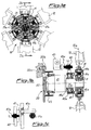
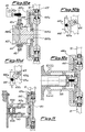
- the apparatus 10 for cooling the cooling liquid in motor vehicles and the like according to the invention is mounted on a device 20 for supporting and transmitting the movement, comprising a support 21 rotating with respect to a fixture 22 joined to the body 22a of the engine by means of bolts 22b or the like and extending in the longitudinal direction with a shaft 21a on which the apparatus 10 is mounted.
- the support 21, and hence the apparatus 10 are kept constantly rotating by means of a pulley 23 which is joined to the support itself and connected in a known manner to a shaft of the vehicle engine.
- the apparatus 10 essentially consists of a central body 11 on which the blades 12 are radially mounted, said blades causing the flow of the air from the outside towards the radiator (not shown) containing the cooling liquid.
- each blade 12 situated inside the central body 11 consists of a pivot pin 31 which has a cylindrical toothing 31a and is radially mounted by means of bearings 31b on the body 11.
- each blade 12 in addition to rotating with the fan 10 on the support 21a, is also able to rotate about its own longitudinal axis 12a as will emerge more clearly below.
- Each gearing 31a is in fact coupled to an actuating device consisting of an associated rectilinear rack 41a which is integral with a tube 41 mounted on the shaft 21a with which it therefore rotates integrally.
- the tube 41 is also connected, by means of a bearing 42a, to a disk 42 which may be translated parallel to the shaft 21a by means of a screw 43a operated by a motor 43 arranged outside the support 21.
- the blade actuation device allows all the blades to be rotated simultaneously and in the same manner through a certain angle which is determined in each case according to needs.
- the external motor may in fact be controlled in a known manner so as to obtain a substantially continuous variation in the angle of orientation of the blades.
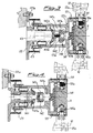
- Fig. 3 shows a first variation of an example of embodiment of the device 140 for actuating rotation of the blades 12.
- the motor 43 is arranged inside the support 121 of the fan.
- Said support is in this case formed by two bell-shaped members 121a and 121b located opposite each other and separated by a partition 121c carrying the shank 141b of a disk 141 on which the racks 141a are mounted.
- said shank 141b extends on the opposite side to that of the racks 141a and is integral, by means of bearings 141c, with a further element 142 axially movable translationwise upon operation of a screw 43a which can be actuated by means of a motor 43, which are coaxially arranged inside the support 121.
- Rotation of the element 142 is prevented by the longitudinal pin 142a.
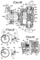
- Figure 4 shows a further embodiment of the apparatus according to the invention, in which the motor 43 is replaced by a double-acting cylinder 143 which is in turn arranged inside the support 121 and the rod 143a of which is connected to the element 142.
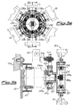
- Figs. 5a and 5b show a further embodiment of the device for actuating rotation of the blades about their longitudinal axes.
- each pivot pin 231 of the blade 12 has a bevel gearing 230 and one of said pivot pins 231 extends longitudinally towards the centre of the fan where it has a cylindrical toothing 231a designed to co-operate with a rack 241a which has a shank 241b.
- the shank 241b is radially connected, by means of a pin 244a which passes through the support 221, via an eyelet 221c, to a bush 244 which is in turn coupled by means of bearing 42a to a disk 42 which can be translated by means of the screw 43a and the motor 43 which are located outside the support 221.
- the bevel gears 230 of the blades are engaged with bevel gears 230a which form a chain for transmission of the rotation to all the blades 12 with the same direction of rotation being maintained for all the blades themselves which are thus oriented simultaneously and in the same manner as required.
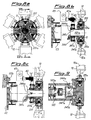
- the fan according to the invention may have a device for actuating rotation of the blades, realized in accordance with a further variation.
- each blade 12 has a bevel gearing 331a on its pivot pin 331; each bevel gearing 331a meshes with a bevel wheel 341a which has a tube 341b extending on the opposite side to the toothing and mounted on the same shaft 321a supporting the fan 11.
- Said tube 341b has, in a suitable position, an eyelet 341c with its axis inclined with respect to the axis of the shaft 321a.
- the tube 341b is radially connected, by means of a pin 344a inserted inside the eyelet 341c, to a bush 344 which is in turn coupled, by means of a bearing 42a, to a disk 42 which can be translated by means of the screw 43a and the motor 43 which are located outside the support 321.
- Fig. 9 shows a drive device consisting of a double-acting cylinder 143 arranged inside the support 121 of the fan in a similar manner to that illustrated in Figs. 4 and 7.
- the rod 143a of the cylinder actuates a cup-shaped member 343a which has a pin 344a radially projecting inwards and inserted into the eyelet 341c of the tube 341b. In this case also the forwards movement of the rod 143a causes rotation of the bevel wheel 341a.
- the drive system may consist of a motor 43 which is arranged inside the support 321 of the fan 10.
- Fig. 10a shows a further variation of an example of the device for rotational actuation of the blades 12 which are mounted in the body 11 of the fan by means of a smooth pivot pin 431 which is axially keyed into a first hole 431b formed at a first end of an associated lever 431a, the other end of which has a second hole 431c which receives a pivot pin 441a radially integral with a plate 441 mounted, by means of a bearing 441d, on a support 441b which is radially connected, by means of a pin 444a, to bush 44 which is in turn coupled, by means of the bearing 42a, to the disk 42 which can be translated by means of the screw 43a and the motor 43 which are located outside the support 421 of the fan.
- the forwards movement/backwards movement of the disk 42 upon operation of the motor 43, causes the forwards movement/backwards movement and simultaneous rotation of the plate 441 and the consequent rotation of the levers 431a which cause the simultaneous and uniform rotation of the blades 12.
- a drive device located inside the support 421 of the fan shown, by way of example in Fig. 11, as a cylinder 143, the rod 143a of which directly causes the translation - and therefore the rotation owing to the constraints imposed - of the plate 451.
- the drive system for rotation located inside the fan support, may consist of an electric motor or the like.
- Figure 12 shows a further example of embodiment of the device for rotational actuation of the blades 12 about their longitudinal axis 12a.
- each blade 12 is mounted in the body 11 of the fan by means of its pivot pin 531 joined to a first end of an L-shaped lever 531a, the other end of which is connected to a disk 541 by means of a radial pin 541a.
- Said disk 541 is in turn coupled, by means of a bearing 541d, to an axial extension 541b designed for engagement with an actuating device 540.
- Said axial extension 541b comprises a bell member 551 with an internal thread 551a designed to engage with a threading 552a of a shaft 552 which is in turn integral with a double-acting hydraulic actuator 543, the piston 543a of which may be rotationally actuated in either direction by means of suitable supplying/discharging of corresponding fluid recirculation ducts 543b respectively leading into the two chambers 543c of the cylinder 543.
- the shaft 552 extends over a short distance outside the cylinder 543 on the opposite side to the fan so as to allow coupling to a device 544 for measuring the rotation performed by the piston 543a.
- This device may for example consist of an encoder which is conventional per se and therefore not described in detail.
- the operating principle of the apparatus is as follows: When manual operation or automatic control produces supplying/discharging of either of the two ducts 543b, the piston 543a rotates in one direction (Fig. 13a) or the other direction (Fig. 13c) causing rotation of the shaft 552 in either direction so that the threading 552a, acting on the internal thread 551a of the bell member 551, produces translation thereof in either direction, causing the forwards movement/backwards movement of the disk 541 which, acting by means of the levers 531a, on each pivot pin 531 of the blades 12, causes the controlled rotation of the latter about their longitudinal axes 12a in one direction (Fig. 13b) or in the other direction (Fig. 13d).
- Fig. 14 shows solely the detail of a variation of embodiment of the devices for controlling rotation which in this case are formed by means of sensors 1544 which are arranged outside the bell member 551. With this configuration it is obviously possible to obtain stepwise control of the position and not continuous control as in the case above.
- Fig. 14 also shows means 600 which are designed make rotation of the shaft 552 and hence the blades 12 irreversible.
- Said means 600 consist of an electromagnet 601 acting on a pin 602 designed to engage with a corresponding seat 603 of the shaft 552, once controlled rotation of the latter has terminated.
- detection means such as sensors and the like which can be associated with programming devices designed to automate adjustment of the angle of rotation of the blades.
Landscapes
- Engineering & Computer Science (AREA)
- Chemical & Material Sciences (AREA)
- Combustion & Propulsion (AREA)
- Mechanical Engineering (AREA)
- General Engineering & Computer Science (AREA)
- Devices For Post-Treatments, Processing, Supply, Discharge, And Other Processes (AREA)
- Structures Of Non-Positive Displacement Pumps (AREA)
Applications Claiming Priority (4)
| Application Number | Priority Date | Filing Date | Title |
|---|---|---|---|
| ITMI981389 | 1998-06-17 | ||
| ITMI981389 IT1301740B1 (it) | 1998-06-17 | 1998-06-17 | Apparecchiatura a pale orientabili per il convogliamento di aria aradiatori di autoveicoli e simili. |
| ITMI981655 | 1998-07-17 | ||
| IT98MI001655A ITMI981655A1 (it) | 1998-07-17 | 1998-07-17 | Apparecchiatura a pale orientabili per il convogliamento di aria a radiatori di autoveicoli e simili |
Publications (2)
| Publication Number | Publication Date |
|---|---|
| EP0967104A2 true EP0967104A2 (de) | 1999-12-29 |
| EP0967104A3 EP0967104A3 (de) | 2001-03-21 |
Family
ID=26331592
Family Applications (1)
| Application Number | Title | Priority Date | Filing Date |
|---|---|---|---|
| EP99201818A Withdrawn EP0967104A3 (de) | 1998-06-17 | 1999-06-08 | Vorrichtung mit verstellbaren Flügeln um Luft zu Kühlern von Motorfahrzeugen u.ä. zu fördern |
Country Status (1)
| Country | Link |
|---|---|
| EP (1) | EP0967104A3 (de) |
Cited By (10)
| Publication number | Priority date | Publication date | Assignee | Title |
|---|---|---|---|---|
| GB2374124A (en) * | 2000-12-20 | 2002-10-09 | Borgwarner Inc | Cooling fan control system for a pitch adjustable variable flow rate fan |
| EP1319814A2 (de) | 2001-12-12 | 2003-06-18 | Baruffaldi S.p.A. | Kühllüfter mit einer Blattverstellung und einer Kupplung für Kraftfahrzeuge |
| FR2910537A1 (fr) * | 2006-12-21 | 2008-06-27 | Renault Sas | Dispositif et procede de regulation du debit de l'air envoye au travers d'un echangeur de chaleur pour moteur a combustion interne de vehicule automobile |
| WO2014023299A1 (de) * | 2012-08-06 | 2014-02-13 | Norbert Kuhn | Axial - ventilator |
| ITMO20130065A1 (it) * | 2013-03-13 | 2014-09-13 | Cnh Italia Spa | Ventilatore a passo variabile e metodo per variare il passo delle pale in un ventilatore. |
| EP2245313A4 (de) * | 2008-01-25 | 2015-04-01 | Skf Ab | Vorrichtung zur steigungsänderung bei einem impeller-/propellerblatt sowie lüfter mit der vorrichtung |
| WO2017080593A1 (en) * | 2015-11-11 | 2017-05-18 | Baruffaldi S.P.A. | Apparatus for actuating and controlling the rotation of blades of fans for cooling the coolant in machines/vehicles. |
| US10589619B2 (en) | 2015-05-19 | 2020-03-17 | Horton, Inc. | Angled torque transmission system and method |
| CN116576152A (zh) * | 2023-07-12 | 2023-08-11 | 中国空气动力研究与发展中心低速空气动力研究所 | 一种风洞风扇桨叶固定装置及可调桨叶安装角风洞风扇 |
| WO2024089631A1 (en) * | 2022-10-28 | 2024-05-02 | Baruffaldi S.P.A. | Double-bearing support group for a fan for cooling vehicles |
Family Cites Families (10)
| Publication number | Priority date | Publication date | Assignee | Title |
|---|---|---|---|---|
| US3006417A (en) * | 1961-10-31 | Axial flow fans | ||
| US1377400A (en) * | 1915-04-16 | 1921-05-10 | Coppus Engineering And Equipme | Blower |
| US1712883A (en) * | 1926-06-05 | 1929-05-14 | Charles S Groner | Adjustable fan |
| US2397183A (en) * | 1943-08-17 | 1946-03-26 | Westinghouse Electric Corp | Fluid impeller drive |
| US3054458A (en) * | 1959-07-11 | 1962-09-18 | Marsico Corrado | Variable pitch fan |
| US3177949A (en) * | 1963-05-07 | 1965-04-13 | Lowell T Caston | Reversible fan |
| US3603698A (en) * | 1969-11-19 | 1971-09-07 | Nordisk Ventilator | Axial flow fan wheel |
| US4047836A (en) * | 1976-05-03 | 1977-09-13 | The Budd Company | Phase change means for a power driven device, such as a fan |
| US4090812A (en) * | 1976-11-19 | 1978-05-23 | The United States Of America As Represented By The Secretary Of The Navy | Axial fan with automatically controlled variable pitch blades |
| DE3022211A1 (de) * | 1980-06-13 | 1981-12-24 | M.A.N. Maschinenfabrik Augsburg-Nürnberg AG, 8000 München | Kuehlanlage fuer eine fluessigkeitsgekuehlte verbrennungskraftmaschine |
-
1999
- 1999-06-08 EP EP99201818A patent/EP0967104A3/de not_active Withdrawn
Non-Patent Citations (1)
| Title |
|---|
| None |
Cited By (14)
| Publication number | Priority date | Publication date | Assignee | Title |
|---|---|---|---|---|
| GB2374124A (en) * | 2000-12-20 | 2002-10-09 | Borgwarner Inc | Cooling fan control system for a pitch adjustable variable flow rate fan |
| GB2374124B (en) * | 2000-12-20 | 2003-06-25 | Borgwarner Inc | Fan control system |
| EP1319814A2 (de) | 2001-12-12 | 2003-06-18 | Baruffaldi S.p.A. | Kühllüfter mit einer Blattverstellung und einer Kupplung für Kraftfahrzeuge |
| FR2910537A1 (fr) * | 2006-12-21 | 2008-06-27 | Renault Sas | Dispositif et procede de regulation du debit de l'air envoye au travers d'un echangeur de chaleur pour moteur a combustion interne de vehicule automobile |
| EP2245313A4 (de) * | 2008-01-25 | 2015-04-01 | Skf Ab | Vorrichtung zur steigungsänderung bei einem impeller-/propellerblatt sowie lüfter mit der vorrichtung |
| WO2014023299A1 (de) * | 2012-08-06 | 2014-02-13 | Norbert Kuhn | Axial - ventilator |
| WO2014140149A1 (en) * | 2013-03-13 | 2014-09-18 | Cnh Industrial Italia S.P.A. | A variable pitch fan and a method for varying the blade pitch in a fan |
| ITMO20130065A1 (it) * | 2013-03-13 | 2014-09-13 | Cnh Italia Spa | Ventilatore a passo variabile e metodo per variare il passo delle pale in un ventilatore. |
| US20160025102A1 (en) * | 2013-03-13 | 2016-01-28 | Cnh Industrial America Llc | A variable pitch fan and a method for varying the blade pitch in a fan |
| US10589619B2 (en) | 2015-05-19 | 2020-03-17 | Horton, Inc. | Angled torque transmission system and method |
| WO2017080593A1 (en) * | 2015-11-11 | 2017-05-18 | Baruffaldi S.P.A. | Apparatus for actuating and controlling the rotation of blades of fans for cooling the coolant in machines/vehicles. |
| WO2024089631A1 (en) * | 2022-10-28 | 2024-05-02 | Baruffaldi S.P.A. | Double-bearing support group for a fan for cooling vehicles |
| CN116576152A (zh) * | 2023-07-12 | 2023-08-11 | 中国空气动力研究与发展中心低速空气动力研究所 | 一种风洞风扇桨叶固定装置及可调桨叶安装角风洞风扇 |
| CN116576152B (zh) * | 2023-07-12 | 2023-09-22 | 中国空气动力研究与发展中心低速空气动力研究所 | 一种风洞风扇桨叶固定装置及可调桨叶安装角风洞风扇 |
Also Published As
| Publication number | Publication date |
|---|---|
| EP0967104A3 (de) | 2001-03-21 |
Similar Documents
| Publication | Publication Date | Title |
|---|---|---|
| EP0967104A2 (de) | Vorrichtung mit verstellbaren Flügeln um Luft zu Kühlern von Motorfahrzeugen u.ä. zu fördern | |
| US6257177B1 (en) | Water pump for the cooling circuit of an internal combustion engine | |
| EP1872985B1 (de) | Verstellsystem mit integriertem Warmluftauslass | |
| EP2715085B1 (de) | Drehzahlregelsystem für motorgebläse | |
| EP1703173B1 (de) | Antriebsachse mit veränderlicher Öl-Durchflussmenge | |
| US6286380B1 (en) | Automatic speed-change apparatus for a gear transmission | |
| US20180172009A1 (en) | Valve Assembly Integrated into a Coolant Pump and Method for Controlling the Same | |
| US20090175742A1 (en) | Hydraulic supply system for a motor vehicle | |
| US2225209A (en) | Motor cooling control | |
| EP3374612B1 (de) | Vorrichtung zur betätigung und steuerung der rotation von schaufeln von gebläsen zur kühlung des kühlmittels in maschinen/fahrzeugen | |
| JP2000505522A (ja) | 自動車用クーラントポンプ | |
| US7229250B2 (en) | Control system for variable pitch fan | |
| EP2310218B1 (de) | Belüftungssystem | |
| EP1319814B1 (de) | Kühllüfter mit einer Blattverstellung und einer Kupplung für Kraftfahrzeuge | |
| KR20100116605A (ko) | 냉각 제어를 위한 방법 및 장치와 엔진 | |
| KR20050061626A (ko) | 엔진의 냉각수 분배장치 | |
| DE102014010983B4 (de) | Getriebevorrichtung, umfassend ein Getriebe und einen Lüfter | |
| EP1768889A1 (de) | Verstellung für lenkhebel für hydrostatischen antrieb | |
| JP2009521632A (ja) | エンジン操作機 | |
| US12504200B2 (en) | Fin arrangement of a cooling air opening | |
| JP4059055B2 (ja) | 冷却液の注入方法、及びこの注入方法に用いる流量制御バルブ | |
| US12241476B2 (en) | Cooling fan assembly | |
| KR0142727B1 (ko) | 차량용 가변식 쿨링장치 | |
| CN207711753U (zh) | 一种汽车风道流量传感器 | |
| US8313304B2 (en) | On-demand on-off water pump assembly |
Legal Events
| Date | Code | Title | Description |
|---|---|---|---|
| PUAI | Public reference made under article 153(3) epc to a published international application that has entered the european phase |
Free format text: ORIGINAL CODE: 0009012 |
|
| AK | Designated contracting states |
Kind code of ref document: A2 Designated state(s): AT BE CH CY DE DK ES FI FR GB GR IE IT LI LU MC NL PT SE |
|
| AX | Request for extension of the european patent |
Free format text: AL;LT;LV;MK;RO;SI |
|
| PUAL | Search report despatched |
Free format text: ORIGINAL CODE: 0009013 |
|
| AK | Designated contracting states |
Kind code of ref document: A3 Designated state(s): AT BE CH CY DE DK ES FI FR GB GR IE IT LI LU MC NL PT SE |
|
| AX | Request for extension of the european patent |
Free format text: AL;LT;LV;MK;RO;SI |
|
| RIC1 | Information provided on ipc code assigned before grant |
Free format text: 7B 60K 11/04 A, 7F 04D 29/36 B |
|
| AKX | Designation fees paid | ||
| REG | Reference to a national code |
Ref country code: DE Ref legal event code: 8566 |
|
| STAA | Information on the status of an ep patent application or granted ep patent |
Free format text: STATUS: THE APPLICATION IS DEEMED TO BE WITHDRAWN |
|
| 18D | Application deemed to be withdrawn |
Effective date: 20010922 |