EP0967110B1 - Mécanisme d'inclinaison pour sièges de véhicules - Google Patents
Mécanisme d'inclinaison pour sièges de véhicules Download PDFInfo
- Publication number
- EP0967110B1 EP0967110B1 EP99304880A EP99304880A EP0967110B1 EP 0967110 B1 EP0967110 B1 EP 0967110B1 EP 99304880 A EP99304880 A EP 99304880A EP 99304880 A EP99304880 A EP 99304880A EP 0967110 B1 EP0967110 B1 EP 0967110B1
- Authority
- EP
- European Patent Office
- Prior art keywords
- arm member
- cam element
- hinge pin
- slide
- cam
- Prior art date
- Legal status (The legal status is an assumption and is not a legal conclusion. Google has not performed a legal analysis and makes no representation as to the accuracy of the status listed.)
- Expired - Lifetime
Links
Images



Classifications
-
- B—PERFORMING OPERATIONS; TRANSPORTING
- B60—VEHICLES IN GENERAL
- B60N—SEATS SPECIALLY ADAPTED FOR VEHICLES; VEHICLE PASSENGER ACCOMMODATION NOT OTHERWISE PROVIDED FOR
- B60N2/00—Seats specially adapted for vehicles; Arrangement or mounting of seats in vehicles
- B60N2/02—Seats specially adapted for vehicles; Arrangement or mounting of seats in vehicles the seat or part thereof being movable, e.g. adjustable
- B60N2/22—Seats specially adapted for vehicles; Arrangement or mounting of seats in vehicles the seat or part thereof being movable, e.g. adjustable the back-rest being adjustable
- B60N2/235—Seats specially adapted for vehicles; Arrangement or mounting of seats in vehicles the seat or part thereof being movable, e.g. adjustable the back-rest being adjustable by gear-pawl type mechanisms
- B60N2/2356—Seats specially adapted for vehicles; Arrangement or mounting of seats in vehicles the seat or part thereof being movable, e.g. adjustable the back-rest being adjustable by gear-pawl type mechanisms with internal pawls
- B60N2/236—Seats specially adapted for vehicles; Arrangement or mounting of seats in vehicles the seat or part thereof being movable, e.g. adjustable the back-rest being adjustable by gear-pawl type mechanisms with internal pawls linearly movable
Definitions
- the present invention relates to a reclining mechanism for a vehicle seat for adjusting an inclined angle of a back rest of the seat relative to a seat cushion.
- a reclining mechanism for a vehicle seat which is composed of a pair of ann members for attachment to a frame structure of a seat cushion and to a frame structure of a back rest, the arm members being connected by means of a hinge pin for relative rotation about the hinge pin, a slide pawl slidably coupled with one of the arm members to be moved in a radial direction with respect to the hinge pin, and a cam element mounted on the hinge pin for rotation therewith and engaged with the slide pawl for maintaining the slide pawl in engagement with a ratchet portion of the other of the arm members and for disengaging the slide pawl from the ratchet portion when it is rotated with the hinge pin.
- the relative rotation of the arm members is restricted by engagement of the slide pawl with the ratchet portion to lock the back rest at an inclined angle and is permitted by disengagement of the slide pawl from the ratchet portion for adjustment of the inclined angle of the back rest.
- the engagement of the slide pawl with the ratchet portion of the arm member is maintained in a condition where the slide pawl is pressed by engagement with a portion of the cam element.
- the cam element is rotated with the hinge pin to disengage the slide pawl from the ratchet portion of the arm member, the slide pawl is retracted by engagement with a portion of the cam element. If the reclining mechanism is applied with a load, the slide pawl is slightly rotated due to an error in assembly of the component parts of the reclining mechanism. This results in looseness in engagement of the slide pawl with the ratchet portion of the arm member.
- a reclining mechanism for a vehicle seat which comprises a first arm member for attachment to a frame structure of a seat cushion or a back rest of the vehicle seat, a second arm member for attachment to a frame structure of the other of the back rest or the seat cushion, the second arm member being connected with the first arm member by means of a hinge pin for relative rotation about the hinge pin and having a semi-circular ratchet portion concentric with the hinge pin, a slide pawl slidably coupled with the first arm member in a radial direction with respect to the hinge pin to be moved toward and away from the ratchet portion of the second arm member, and a cam element slidably coupled with the first arm member in a lateral direction perpendicular to the slide pawl and operatively connected with the hinge pin to be moved by rotation of the hinge pin in the lateral direction for engaging the slide pawl with the ratchet portion of the second arm member and for disengaging the slide pawl from the
- the first arm member is formed with a first guide groove in a radial direction with respect to the hinge pin and a second guide groove perpendicular to the first guide groove
- the slide pawl is slidably coupled within the first guide groove while the cam element is slidably coupled within the second guide groove.
- the cam element is formed with an elongated lateral hole in the lateral direction perpendicular to the slide pawl, and the hinge pin is inserted across the lateral hole of the cam element for connection to the first and second arm members and being engaged with a portion of the lateral hole of the cam element.
- a reclining mechanism for a vehicle seat which comprises a first arm member for attachment to a frame structure of a seat cushion or a back rest of the vehicle seat, a second arm member for attachment to a frame structure of the other of the back rest or the seat cushion, the second arm member being connected with the first arm member by means of a hinge pin for relative rotation about the hinge pin and having a pair of diametrically opposed semi-circular ratchet portions concentric with the hinge pin, a pair of diametrically opposed slide pawls slidably coupled with the first arm member in a radial direction with respect to the hinge pin to be moved toward and away from the ratchet portions of the second arm member, and a cam element slidably coupled with the first arm member in a lateral direction perpendicular to the slide pawls and disposed between the slide pawls, the cam element being operatively connected with the hinge pin to be moved by rotation of the hinge pin in the lateral direction for engaging
- the slide pawls each are formed at their outer ends with a semi-circular toothed portion for engagement with each ratchet portion of the second arm members and at their inner ends with a pair of laterally spaced projections to be engaged with opposite flat surfaces of the cam element for maintaining the slide pawls in engagement with the ratchet portions of the second arm member, and wherein the cam element is formed with the opposite flat surfaces thereof with a pair of laterally spaced recesses to be engaged with the spaced projections of the slide pawls for permitting disengagement of the slide pawls from the ratchet portions of the second arm member.
- a cam plate is assembled with the cam element to disengage the slide pawls from the ratchet portions of the second arm member by engagement therewith when the hinge pin is rotated against the load of the torsion spring to cause lateral movement of the cam element.
- the cam plate is formed with a pair of diametrically opposed cam slots which are engaged with a pair of cam pins provided on the slide pawls to disengage the slide pawls from the ratchet portions of the second arm member when the hinge pin is rotated against the load of the torsion spring to cause lateral movement of the cam element.
- a movable cam plate may be assembled with the hinge pin to be rotated with the hinge pin and rotatably connected with the cam element to cause lateral movement of the cam element when rotated with the hinge pin, wherein the movable cam plate is formed with a pair of diametrically opposed cam slots which are engaged with a pair of cam pins provided on the slide pawls to disengage the slide pawls from the ratchet portions of the second arm member when the hinge pin is rotated against the load of the torsion spring.
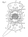
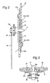
- a reclining mechanism for a vehicle seat in accordance with the present invention, which reclining mechanism is composed of a first arm member 11 for attachment to a frame structure of a seat cushion (not shown) of the vehicle seat, a second arm member 12 for attachment to a frame structure of a back rest (not shown) of the vehicle seat, a pair of slide pawls 13 and 14, a cam element 15, a torsion spring 16, a hinge pin 17 and an operation lever 18.
- the first and second arm members 11 and 12 are coupled to contain the slide pawls 13, 14 and cam element 15 therein.
- the second arm member 12 is connected to the first arm member 11 by means of the hinge pin 17 for relative rotation about the hinge pin 17.
- the reclining mechanism is assembled with the vehicle seat in such a manner that the second arm member 12 is locked to the first arm member 11 at a selected position to retain the back rest at an inclined angle and that the second arm member is released from the first arm member to permit adjustment of the inclined angle of the back rest.
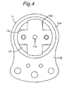
- the first arm member 11 has an upper portion 11a formed to contain the slide pawls 13, 14 and cam element 15 and a lower portion 11b for attachment to the frame structure of the seat cushion.
- the upper portion 11a of first arm member 11 is formed therein with a vertical guide groove 11d across a central hole 11c and a lateral guide groove 11e perpendicular to the vertical groove 11d.
- the vertical guide groove 11d is slightly extended outward from the inner periphery of a circular recess 11f formed in the upper portion 11a, while the lateral groove 11e is extended to the inner periphery of the circular recess 11f.
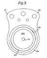
- the second arm member 12 has a lower portion 12a formed to contain the slide pawls 13, 14 and cam element 15 and an upper portion 12b for attachment to the frame structure of the back rest.
- the lower portion 12a of second arm member 12 is formed with a circular recess 12d concentric with a central hole 12c.
- the circular recess 12d and central hole 12c are formed in the lower portion 12a of second arm member 12 to correspond with the circular recess 11f and central hole 11c formed in the upper portion 11a of first arm member 11.
- the circular recess 12d of second arm member 12 is formed at its inner periphery with a pair of diametrically opposed semi-circular ratchet portions 12e.
- the slide pawls 13 and 14 are formed in the same width and thickness. As shown in Fig. 6, the slide pawls 13 and 14 are formed at their outer ends with semi-circular toothed portions 13a and 14a and at their inner ends with flat surfaces 13b and 14b and each pair of tapered projections 13c and 14c.
- the thickness of each of the slide pawls 13, 14 is determined to correspond with a space defined by the vertical guide groove 11d of first arm member 11 and the circular recess 12d of second arm member 12, and the width of each of the slide pawls 13, 14 is determined to correspond with the width of the vertical guide groove 11d of first arm member 11.
- the semi-circular toothed portions 13a, 14a of slide pawls 13, 14 are positioned to be engaged with and disengaged from the ratchet portions 12e of second arm member 12.
- the tapered projections 13c, 14c of slide pawls 13, 14 are formed to be located in the lateral guide groove 11e of first arm member 11 in a condition where the slide pawls 13, 14 are maintained in engagement with the ratchet portions 12e of second arm member 12.
- the cam element 15 is in the form of a rectangular plate which is formed at its central portion with an elongated lateral hole 15a and at its opposite flat surfaces with each pair of laterally spaced recesses 15b, 15c.
- the lateral hole 15a is formed at one side thereof with a radial recess 15d.
- the thickness of the cam element 15 is determined to correspond with a space defined by the lateral guide groove 11e of first arm member 11 and the circular recess 12d of second arm member 12.
- cam element 15 is determined to correspond with the width of lateral groove 11e of first arm member 11, and the elongated lateral hole 15a of cam element 15 is formed to allow rotation and lateral movement of cam element 15 relative to the hinge pin 17.
- the laterally spaced recesses 15b, 15c of cam element 15 each are formed to be brought into engagement with and disengaged from the laterally spaced projections 13c, 14c of slide pawls 13, 14.
- the radial recess 15d of cam element 15 is maintained in engagement with a radial projection 17a of hinge pin 17.
- the slide pawls 13, 14 are slidably engaged with the vertical guide groove 11d of first arm member 11, and the cam element 15 is slidably engaged with the lateral guide groove 11e of first arm member 11 and disposed between the slide pawls 13 and 14.
- the second arm member 12 is coupled at its lower portion 12a with the upper portion 11a of first arm member 11 for relative rotation and united with the first arm member 11 by engagement with upper and lower retainer plates 19a and 19b welded to the upper and lower portions 12a and 11a of second and first arm members 12 and 11.
- the retainer plate 19a is slidably engaged at its lower end portion with a semi-circular upper end of first arm member 11, while the retainer plate 19b is slidably engaged at its upper end portion with a semi-circular lower end of second arm member 12.
- the slide pawls 13, 14 and cam element 15 are contained in the circular recess 12d of second arm member 12.
- the hinge pin 17 is inserted into the central hole 12c of second arm member 12 across the central hole 11c of first arm member 11 and the elongated lateral hole 15a of cam element 15.
- the radial projection 17a of hinge pin 17 is engaged with the recess 15d of cam element 15.
- a support plate 19c is riveted to the upper portion 11a of first arm member 11 and engaged with a stepped portion of hinge pin 17 to retain the hinge pin 17 in position.
- the support plate 19c is formed with a pair of hooks 19d.
- the torsion spring 16 is engaged at its inner end with an outer end portion of hinge pin 17 and at its other end with one of the hooks 19d to bias the hinge pin 17 in a counterclockwise direction so that the cam element 15 is retained at a central portion of lateral guide groove 11e as shown in Fig. 6(a).
- the operation lever 18 is fixed to the outer end of hinge pin 17.
- cam element 15 The rightward movement of cam element 15 is restricted by abutment of the cam element 15 against the hinge pin 17 at the left-hand end of lateral hole 15a.
- the tapered projections 13c, 14c of slide pawls 13, 14 are brought into engagement with the recesses 15b, 15c of cam element 15 to disengage the slide pawls 13, 14 from the ratchet portions 12e of second arm member 12 as shown in Fig. 6(c).
- the slide pawls 13, 14 While the operation lever 18 is retained in its operated position, the slide pawls 13, 14 are retained in their disengaged positions from the ratchet portions 12e of second arm member 12 to permit adjustment of the inclined angle of the back rest.
- each pair of spaced projections 13c, 14c of slide pawls, 13, 14 engaged with the opposite flat surfaces of cam element 15 is useful to firmly maintain the slide pawls 13, 14 in engagement with the ratchet portions 12e of second arm member 12 even if the reclining mechanism is applied with a load.
- the hinge pin 17 is assembled across the elongated lateral hole 15a of cam element 15 and engaged at its radial projection 17a with the recess 15d of the elongated lateral hole 15a, the lateral movement of cam element 15 is smoothly effected by rotation of the hinge pin 17.
- a cam plate 21 is assembled with the cam element 15 to move the slide pawls 13, 14 toward and away from the ratchet portions 12e of second arm member 12 in accordance with lateral movement of the cam element 15.
- the cam plate 21 is in the form of a rectangular plate 21a formed at its opposite sides with a pair of arm portions 21b and formed with a pair of vertically spaced cam slots 21c.
- the cam plate 21 is fixed to the cam element 15 at its both arm portions 21b for movement therewith.
- the cam slots 21c each are formed with an inclined portion and a horizontal portion.
- the slide pawls 13, 14 are provided thereon with cam pins 13d, 14d which are slidably engaged with the cam slots 21c of cam plate 21.
- the spaced projections 13c, 14c of slide pawls 13, 14 are disengaged from the recesses 15b, 15c of cam element 15 and brought into engagement with the opposite flat surfaces of cam element 15 to engage the slide pawls 13, 14 with the ratchet portions 12e of second arm member 12, while the cam plate 21 is moved leftward with the cam element 15 so that the cam pins 13d, 14d are located in the horizontal portions of cam slots 21c.
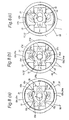
- Figs. 9(a) - 9(c) Illustrated in Figs. 9(a) - 9(c) is a second modification of the reclining mechanism shown Figs. 1 to 3.
- a movable cam plate 22 is assembled with the cam element 15 to move the slide pawls 13, 14 toward and away from the the ratchet portions 12e of second arm member 12 in accordance with lateral movement of the cam element 15.
- the cam element 15 is provided thereon with a pair of diametrically opposed support pins 15e, 15f for engagement with the cam plate 22.
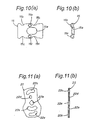
- Figs. 10(a) and 10(b) the cam element 15 is provided thereon with a pair of diametrically opposed support pins 15e, 15f for engagement with the cam plate 22.
- the cam plate 22 is formed at its central portion with a square hole 22a and formed with a pair of diametrically opposed semi-circular cam slots 22b and 22c.
- the cam plate 22 is further formed with a circular hole 22d for engagement with the support pin 15e of cam element 15 and a semi-circular elongated hole 22e which is slidably coupled with the support pin 15f of cam element 15 to permit rotation of the cam plate 22 relative to the cam plate 15.
- the cam plate 22 is assembled with the hinge pin 17 at its square hole 22a for rotation therewith and coupled with the support pins 15e, 15f of cam element 15 at its circular hole 22d and semi-circular elongated hole 22e.
- the slide pawls 13, 14 are provided thereon with cam pins 13d, 14d which are slidably engaged with the cam slots 22b, 22c of cam plate 22.
- the cam plate 22 is rotated with the hinge pin 17 to cause lateral movement of the cam element 15 in a direction perpendicular to the slide pawls 13 and 14.
- the slide pawls 13, 14a are maintained in engagement with the ratchet portions 12e of second arm member 12.
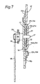
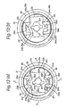
- Figs. 12 (a) - 12(b) and 14 Illustrated in Figs. 12 (a) - 12(b) and 14 is a third modification of the reclining mechanism shown in Figs. 1 to 3, wherein the first arm member 11 is replaced with a first disk member 31 for attachment to the frame structure of the seat cushion and a second disk member 32 for attachment to the frame structure of the back rest.
- the first disk member 31 has a circular recess 31a and vertical and lateral guide grooves 31b, 31c formed in the circular recess 31a.
- the second disk member 32 has a circular recess 32a formed at its inner periphery with a pair of diametrically opposed ratchet portions 32b.
- the second disk member 32 is coupled within the circular recess 31a of first disk member 31 for relative rotation in such a manner that a radial projection 32c of second disk member 32 is located in a semi-circular recess 31d formed in the inner periphery of circular recess 31a of first disk member 31.
- the radial projection 32c of second disk member 32 is provided to restrict rotation of the second disk member 32 relative to the first disk member 31 by engagement with a stepped end of the semi-circular recess 31d.
- the first and second disk members 31 and 32 are united with each other by means of an annular bracket 39a coupled therewith.
- slide pawls 33, 34 and cam element 35 which are contained in a space defined by the circular recesses 31a and 32a of disk members 31 and 32.
- the slide pawls 33, 34 are slidably coupled within the vertical guide groove 31b of first disk member 31, while the cam element 35 is slidably coupled within the lateral guide groove 31c and interposed between the slide pawls 33 and 34.
- the slide pawl 33 is formed at its outer end with a semi-circular toothed portion and at its inner end with a pair of tapered projections 33a and a recessed portion 33b between the tapered projections 33a.
- the slide pawl 34 is formed at its outer end with a semi-circular toothed portion and at its inner end with a pair of tapered projections 34a and a recessed portion 34b between the tapered projections 34a.
- the cam element 35 is formed at its opposite flat surfaces with each pair of laterally spaced recesses 35a, 35b and a pair of radially spaced projections 35c, 35d each of which is located between the recesses 35a and between the recesses 35b.
- a hinge pin 37 is integrally formed with a connecting arm 37a which is located in an aperture 35e formed in the cam element 35 and engaged with an inner periphery of the aperture 35e.
- the hinge pin 37 is assembled with the disk members 31, 32 in such a manner as to permit rotation of the second disk member 32 relative to the first disk member 31 and loaded by a torsion spring 36 in a counterclockwise direction.
- the hinge pin 37 is rotated by an operation level (not shown) against the load of torsion spring 36 in a clockwise direction, the cam element 35 is moved rightward by engagement with the connecting arm 37a of hinge pin 37.
- the cam element 35 When the operation level is released to rotate the hinge pin 37 in the counterclockwise direction under the load of torsion spring 36, the cam element 35 is moved leftward by engagement with the connecting arm 37a of hinge pin 37.
- the reference numeral 39b designates the frame structure of the seat cushion
- the reference numeral 39c designates the from structure of the back rest.
- the radial projection 32c of second disk member 32 is provided to restrict relative rotation of the second disk member 32 to the first disk member 31 by engagement therewith, the adjustment of the inclined angle of the back rest can be restricted in a predetermined extent in a simple construction.
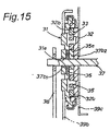
- Fig. 15 Illustrated in Fig. 15 is a modification of the reclining mechanism shown in Figs. 1 to 3.
- the modified reclining mechanism is composed of the same component parts as the disk members 31, 32, slide pawls 33, 34 and cam element 35 in the reclining mechanism shown in Figs. 13 and 14.
- the hinge pin 37 is in the form of a longitudinal connecting rod
- the connecting arm 37a of cam element 37 is replaced with an arm portion 37b2 which is integrally formed with a sleeve 37b1 splined to the connecting rod 37 for rotation therewith.
- the arm portion 37b2 of sleeve 37b1 is engaged with the inner periphery of aperture 35e of cam element 35 as shown in Fig. 12(a).
- the torsion spring 36 is disposed between the first disk member 31 and the arm portion 37b2 of sleeve 37b1 and assembled with the sleeve 37b1 to bias the connecting rod 37 in a counterclockwise direction.
- the connecting rod 37 can be adapted to operatively connect a pair of laterally spaced reclining mechanisms (not shown) mounted to opposite sides of a vehicle seat in a simple construction.
Landscapes
- Engineering & Computer Science (AREA)
- Aviation & Aerospace Engineering (AREA)
- Transportation (AREA)
- Mechanical Engineering (AREA)
- Chairs For Special Purposes, Such As Reclining Chairs (AREA)
- Seats For Vehicles (AREA)
Claims (12)
- Mécanisme d'inclinaison pour un siège de véhicule, comprenant un premier organe formant bras (11), pour assurer la fixation à une structure de cadre d'un coussin de siège ou d'un dossier du siège de véhicule, et un deuxième organe formant bras (12), pour assurer la fixation à une structure de cadre de l'autre du dossier ou du coussin de siège, le deuxième organe formant bras étant connecté au premier organe formant bras, à l'aide d'une tige de charnière (17), pour permettre une rotation relative autour de la tige de charnière et ayant une partie de cliquet (12e) circulaire, concentrique à la tige de charnière,
caractérisé en ce que le mécanisme d'inclinaison comprend un linguet coulissant (13), couplé à coulissement au premier organe formant bras (11) dans une direction radiale par rapport à la tige de charnière, pour être déplacé vers et à l'écart de la partie de cliquet (12e) du deuxième organe formant bras (12), et un élément formant came (15) couplé à coulissement au premier organe formant bras (11), dans une direction latérale perpendiculairement au linguet coulissant et relié fonctionnellement à la tige de charnière (17) pour être déplacée par la rotation de la tige de charnière dans la direction latérale pour mettre en prise le linguet coulissant avec la partie de cliquet du deuxième organe formant bras et pour mettre hors de prise le linguet coulissant vis-à-vis de la partie de cliquet du deuxième organe formant bras,
dans lequel la tige de charnière (17) est chargée par un ressort de torsion (16) assemblé sur elle, afin de solliciter l'élément formant came (15) dans la direction latérale, pour maintenir le linguet coulissant en prise avec la partie de cliquet du deuxième organe formant bras, le linguet coulissant (13) étant former pour présenter, à son extrémité extérieure, une partie dentée (13a) semi-circulaire, destinée à être mise en prise avec la partie de cliquet (12e) du deuxième organe formant bras (12) et, pour présenter à son extrémité intérieure, une paire de saillies (13c) espacées latéralement, devant venir en prise avec une surface d'extrémité de l'élément formant came (15), et l'élément formant came (15) est formé pour présenter, à sa surface d'extrémité, une paire de cavités (15b) espacées latéralement, devant venir en prise avec les saillies (13b) espacées du linguet coulissant (13), pour permettre une mise hors de prise du linguet coulissant (13) vis-à-vis de la partie de cliquet du deuxième organe formant bras. - Mécanisme d'inclinaison selon la revendication 1, dans lequel le deuxième organe formant bras (12) est couplé coaxialement au premier organe formant bras (11), pour permettre une rotation relative autour de la tige de charnière (17).
- Mécanisme d'inclinaison selon la revendication 1, dans lequel le premier organe formant bras (11) est formé pour présenter une première gorge de guidage (11d), dans une direction radiale par rapport à la tige de charnière (17), et une deuxième gorge de guidage (11e) perpendiculaire à la première gorge de guidage (11d), et dans lequel le linguet coulissant (13) est couplé à coulissement à l'intérieur de la première gorge de guidage (11d), tandis que l'élément formant came (15) est couplé à coulissement à l'intérieur de la deuxième gorge de guidage (11e).
- Mécanisme d'inclinaison selon la revendication 1, dans lequel l'élément formant came (15) est muni d'un trou latéral (15a) allongé, orienté dans la direction perpendiculaire au linguet coulissant (13), et dans lequel la tige de charnière (17) est insérée dans le trou latéral (15a) de l'élément formant came, pour établir une connexion aux premier et deuxième organes formant bras et est mis en prise avec une partie du trou latéral (15a) de l'élément formant came.
- Mécanisme d'inclinaison pour un siège de véhicule, comprenant un premier organe formant bras (11), pour assurer la fixation à une structure de cadre d'un coussin de siège ou d'un dossier du siège de véhicule, et un deuxième organe formant bras (12), pour assurer la fixation à une structure de cadre de l'autre du dossier ou du coussin de siège, le deuxième organe formant bras étant relié au premier organe formant bras, à l'aide d'une tige de charnière (17), pour permettre une rotation relative autour de la tige de charnière et ayant une partie de cliquet circulaire (12e) concentrique à la tige de charnière,
caractérisé en ce que le mécanisme d'inclinaison comprend une paire de linguets coulissant (13), couplés à coulissement au premier organe formant bras (11) dans une direction radiale par rapport à la tige de charnière, devant être déplacée vers et à l'écart vis-à-vis de la partie de cliquet (12e) du deuxième organe formant bras (12), et un élément de came (15), couplé à coulissement au premier organe formant bras (11), dans une direction perpendiculaire aux cliquets coulissants et disposé entre les cliquets coulissants, l'élément formant came étant relié fonctionnellement à la tige de charnière (17), pour être déplacé par une rotation de la tige de charnière dans une direction latérale, pour mise en prise des linguets coulissants avec la partie de cliquet du deuxième organe formant bras et pour mettre hors de prise les linguets coulissants vis-à-vis de la partie de cliquet du deuxième organe formant bras, et
en ce que la tige de charnière (17) est chargée, par un ressort de torsion (16) assemblé sur elle, afin de solliciter l'élément formant came (15) dans la direction latérale, afin de maintenir les linguets coulissants en prise avec la partie de cliquet du deuxième organe formant bras. - Mécanisme d'inclinaison selon la revendication 5, dans lequel les cliquets coulissants (13) sont chacun formés pour présenter, à leurs extrémités extérieures, d'une partie dentée (13a) semi-circulaire, devant venir en prise avec la partie de cliquet (12e) des deuxièmes organes formant bras (12), et, pour présenter à leurs extrémités intérieures, une paire de saillies (13c) espacées latéralement, devant être mises en prise avec des surfaces d'extrémité opposées de l'élément formant came (15), pour maintenir les linguets coulissants (13) en prise avec la partie de cliquet du deuxième organe formant bras, et dans lequel l'élément formant came est formé pour présenter, au niveau de ses surfaces d'extrémités opposées, une paire de cavités (15b) espacées latéralement, devant être mises en prise avec les saillies (13c) espacées des linguets coulissants afin de permettre une mise hors de prise des linguets coulissants vis-à-vis de la partie de cliquet du deuxième organe formant bras.
- Mécanisme d'inclinaison selon la revendication 6, dans lequel une plaque formant came (21) est assemblée avec l'élément formant came (15), pour mettre hors de prise les linguets coulissants (13) vis-à-vis de la partie de cliquet du deuxième organe formant bras, par mise en prise avec lui lorsque la tige de charnière (17) est tournée à l'encontre de la charge exercée par le ressort de torsion (16), pour provoquer un déplacement latéral de l'élément formant came (15).
- Mécanisme d'inclinaison selon la revendication 7, dans lequel ladite plaque formant came (21) est munie d'une paire de fentes de cames (21c) diamétralement opposées, mises en prise avec une paire de tiges de cames (13d) prévues sur les linguets coulissants, afin de mettre hors de prise les linguets coulissants vis-à-vis de la partie de cliquet du deuxième organe formant bras, lorsque la tige de charnière est tournée à l'encontre de la force exercée par le ressort de torsion, pour provoquer le déplacement latéral de l'élément formant came.
- Mécanisme d'inclinaison selon la revendication 6, dans lequel une plaque formant came (22) mobile est assemblée à la tige de charnière (17), pour tourner avec elle et reliée à rotation à l'élément formant came (15), pour provoquer un déplacement latéral de l'élément formant came, lors de la rotation avec la tige de charnière (17), et dans lequel la plaque formant came (22) mobile est formée pour présenter une paire de fentes de cames (22b) diamétralement opposées, mises en prise avec une paire de tiges de cames (13d) prévue sur les linguets coulissants (13), pour mettre hors de prise les linguets coulissants vis-à-vis de la partie de cliquet du deuxième organe formant bras, lorsque la tige de charnière est tournée à l'encontre de la charge exercée par le ressort de torsion (16).
- Un mécanisme d'inclinaison selon la revendication 6, dans lequel les linguets coulissants (33) sont chacun munis d'une partie creusée (33b,34b) entre les saillies (33a) espacées de ceux-ci, et dans lequel l'élément formant came (35) est formé pour présenter une paire de saillies radiales (35c,35d), destinées à être mises en prise avec les parties creusées (33b) des linguets coulissants pour mettre hors de prise les linguets coulissants vis-à-vis des parties de cliquets du deuxième organe formant bras, lorsque la tige de charnière est tournée à l'encontre de la charge exercée par le ressort de torsion, afin de provoquer un déplacement latéral de l'élément formant came.
- Mécanisme d'inclinaison selon l'une quelconque des revendications 1 à 4, dans lequel le premier organe formant bras (11) est réalisé sous la forme d'un premier organe discoïde (31), pour fixation à une structure de cadre d'un coussin de siège ou d'un dossier du siège de véhicule, et dans lequel le deuxième organe formant bras (12) est réalisé à la forme d'un deuxième organe discoïde (32), pour fixation à une structure de cadre de l'autre du dossier ou du coussin de siège, le deuxième organe discoïde (32) étant couplé au premier organe discoïde (31), pour permettre une rotation relative et unie au premier organe discoïde (31), au moyen d'un support annulaire (39a) lui étant couplé pour retenir le cliquet coulissant et l'élément formant came s'y trouvant.
- Un mécanisme d'inclinaison selon l'une quelconque des revendications 5, 6 et 10, dans lequel le premier organe formant bras (11) est réalisé sous la forme d'un premier organe discoïde (31) pour fixation à une structure de cadre d'un coussin de siège ou d'un dossier du siège de véhicule, et dans lequel le deuxième organe formant bras (12) est réalisé sous la forme d'un deuxième organe discoïde (32), pour fixation à une structure formant cadre de l'autre du dossier ou du coussin de siège, le deuxième organe discoïde (32) étant couplé au premier organe discoïde (31), pour permettre une rotation relative, et uni au premier organe discoïde (31) au moyen d'un support annulaire (39a) lui étant couplé, pour retenir les linguets coulissants et l'élément formant came y étant contenu.
Applications Claiming Priority (4)
| Application Number | Priority Date | Filing Date | Title |
|---|---|---|---|
| JP17506898 | 1998-06-22 | ||
| JP17506898 | 1998-06-22 | ||
| JP08192699A JP4265024B2 (ja) | 1998-06-22 | 1999-03-25 | リクライニング装置 |
| JP8192699 | 1999-03-25 |
Publications (3)
| Publication Number | Publication Date |
|---|---|
| EP0967110A2 EP0967110A2 (fr) | 1999-12-29 |
| EP0967110A3 EP0967110A3 (fr) | 2001-04-25 |
| EP0967110B1 true EP0967110B1 (fr) | 2005-11-30 |
Family
ID=26422907
Family Applications (1)
| Application Number | Title | Priority Date | Filing Date |
|---|---|---|---|
| EP99304880A Expired - Lifetime EP0967110B1 (fr) | 1998-06-22 | 1999-06-22 | Mécanisme d'inclinaison pour sièges de véhicules |
Country Status (7)
| Country | Link |
|---|---|
| US (3) | US6390557B1 (fr) |
| EP (1) | EP0967110B1 (fr) |
| JP (1) | JP4265024B2 (fr) |
| CN (1) | CN1123460C (fr) |
| DE (1) | DE69928602T2 (fr) |
| ID (1) | ID22960A (fr) |
| TW (1) | TW499303B (fr) |
Families Citing this family (82)
| Publication number | Priority date | Publication date | Assignee | Title |
|---|---|---|---|---|
| JP4457434B2 (ja) * | 1999-08-02 | 2010-04-28 | トヨタ紡織株式会社 | リクライニング装置 |
| JP4552293B2 (ja) * | 2000-08-30 | 2010-09-29 | アイシン精機株式会社 | 車両用シートリクライニング装置 |
| JP3804453B2 (ja) * | 2001-01-19 | 2006-08-02 | トヨタ紡織株式会社 | リクライニング装置 |
| DE10102860A1 (de) | 2001-01-23 | 2002-08-01 | Keiper Gmbh & Co | Beschlag für einen Fahrzeugsitz |
| JP4770067B2 (ja) | 2001-06-07 | 2011-09-07 | トヨタ紡織株式会社 | シートリクライニング装置 |
| FR2833898B1 (fr) * | 2001-12-24 | 2004-03-12 | Faurecia Sieges Automobile | Mecanisme d'articulation pour siege de vehicule et siege equipe d'un tel mecanisme |
| WO2004012560A1 (fr) * | 2002-08-02 | 2004-02-12 | Toyota Boshoku Kabushiki Kaisha | Dispositif inclinable et procede de verrouillage dudit dispositif |
| DE10253054B4 (de) | 2002-11-14 | 2007-01-18 | Keiper Gmbh & Co.Kg | Beschlag für einen Fahrzeugsitz |
| ATE470593T1 (de) | 2003-01-03 | 2010-06-15 | Johnson Controls Tech Co | Fahrzeugsitz mit steuersystem |
| WO2004067313A1 (fr) * | 2003-01-24 | 2004-08-12 | Intier Automotive Inc. | Ensemble fauteuil inclinable pour siege d'automobile pourvu d'une came flottante |
| US6910738B2 (en) | 2003-01-28 | 2005-06-28 | Fisher Dynamics Corporation | Device and method for assembling a recliner mechanism |
| US6890034B2 (en) | 2003-01-28 | 2005-05-10 | Fisher Dynamics Corporation | Compact recliner with locking cams |
| US6869143B2 (en) * | 2003-04-01 | 2005-03-22 | Bae Industries, Inc. | Recliner clutch mechanism for vehicle seat |
| DE10335869A1 (de) * | 2003-08-06 | 2005-03-17 | Keiper Gmbh & Co. Kg | Beschlag für einen Fahrzeugsitz |
| US7261379B2 (en) * | 2003-09-05 | 2007-08-28 | Dura Global Technologies, Inc. | Reclining vehicle seat hinge assembly |
| KR100522496B1 (ko) * | 2003-09-25 | 2005-10-18 | 기아자동차주식회사 | 차량 시트 리클라이너 |
| FR2845045A1 (fr) * | 2003-10-03 | 2004-04-02 | Faurecia Sieges Automobile | Mecanisme d'articulation pour siege de vehicule et siege equipe d'un tel mecanisme |
| DE10355820B3 (de) | 2003-11-28 | 2005-05-19 | Keiper Gmbh & Co. Kg | Rastbeschlag für einen Fahrzeugsitz |
| US20050168034A1 (en) * | 2004-01-21 | 2005-08-04 | Scott Fast | Disc recliner with dual cams |
| US7097253B2 (en) * | 2004-03-11 | 2006-08-29 | Fisher Dynamics Corporation | Round recliner assembly with rear folding latch |
| US7025422B2 (en) * | 2004-03-11 | 2006-04-11 | Fisher Dynamics Corporation | Round recliner assembly with rear folding latch |
| US7100987B2 (en) * | 2004-08-31 | 2006-09-05 | Dura Global Technologies, Inc. | Reclining vehicle seat hinge assembly |
| US7195318B2 (en) * | 2004-11-01 | 2007-03-27 | Das Co., Ltd. | Reclining device of vehicle seat |
| US20060261657A1 (en) * | 2005-05-19 | 2006-11-23 | Xianhu Luo | Core part of flat spring recliner for auto seat angle adjustment |
| US7364236B2 (en) * | 2005-07-15 | 2008-04-29 | Bae Industries, Inc. | O-ring grooved stop rivet for reducing buzz, squeak and rattle associated with a motor actuated seat assembly between upright design and load floor positions |
| US7766429B2 (en) * | 2005-09-26 | 2010-08-03 | Toyota Boshoku Kabushiki Kaisha | Rotation lock device |
| FR2892356B1 (fr) * | 2005-10-24 | 2009-05-01 | Faurecia Sieges Automobile | Mecanisme d'articulation, son procede de fabrication et siege de vehicule comportant un tel mecanisme. |
| US8944977B2 (en) | 2006-04-12 | 2015-02-03 | Daniel N. Foster | Combination ergonomic task chair and exercise device |
| US7517021B2 (en) * | 2006-09-12 | 2009-04-14 | Lear Corporation | Reclining mechanism for vehicle seats |
| CA2666254A1 (fr) * | 2006-10-12 | 2008-04-17 | Johnson Controls Technology Company | Mecanisme de siege inclinable rotatif |
| CN101243922B (zh) * | 2007-02-16 | 2011-05-11 | 湖北中航精机科技股份有限公司 | 一种座椅角度调节装置 |
| JP5050754B2 (ja) * | 2007-09-21 | 2012-10-17 | アイシン精機株式会社 | 車両用シートリクライニング装置 |
| DE112008003017B4 (de) * | 2007-11-09 | 2016-07-21 | Toyota Boshoku K.K. | Lehneneinstellvorrichtung für einen Fahrzeugsitz |
| US7703852B2 (en) * | 2007-12-03 | 2010-04-27 | Lear Corporation | Heavy duty reclining mechanism for vehicle seats |
| WO2009091980A1 (fr) | 2008-01-17 | 2009-07-23 | Fisher Dynamics Corporation | Mécanisme de siège inclinable rond |
| JP5167948B2 (ja) * | 2008-05-22 | 2013-03-21 | トヨタ紡織株式会社 | 車両用シートの連結装置 |
| JP2010035738A (ja) * | 2008-08-04 | 2010-02-18 | Toyota Boshoku Corp | 車両用シートの連結装置 |
| JP2010227188A (ja) * | 2009-03-26 | 2010-10-14 | Aisin Seiki Co Ltd | 車両用シートリクライニング装置 |
| GB0907650D0 (en) | 2009-05-05 | 2009-07-22 | Depuy Int Ltd | Alignment guide |
| JP5326930B2 (ja) * | 2009-08-21 | 2013-10-30 | アイシン精機株式会社 | 車両用シートリクライニング装置 |
| JP5365461B2 (ja) * | 2009-10-14 | 2013-12-11 | トヨタ紡織株式会社 | 乗物シート用リクライニング装置 |
| US9295566B2 (en) * | 2010-05-04 | 2016-03-29 | Depuy International Limited | Alignment guide |
| US20120330319A1 (en) | 2010-05-04 | 2012-12-27 | Depuy International Limited | Alignment guide with spirit level |
| US9358130B2 (en) | 2012-03-29 | 2016-06-07 | DePuy Synthes Products, Inc. | Surgical instrument and method of positioning an acetabular prosthetic component |
| US20120153698A1 (en) * | 2010-12-21 | 2012-06-21 | Imasen Electric Industrial Co., Ltd. | Reclining apparatus |
| CN102145663B (zh) * | 2011-01-27 | 2012-09-05 | 湖北中航精机科技股份有限公司 | 座椅调角器及其自锁机构及具有该调角器的座椅 |
| US9320603B2 (en) | 2012-09-20 | 2016-04-26 | Depuy (Ireland) | Surgical instrument system with multiple lengths of broaches sharing a common geometry |
| JP5969873B2 (ja) * | 2012-09-27 | 2016-08-17 | 富士機工株式会社 | 車両用シートリクライニング装置 |
| US9399418B2 (en) | 2013-01-24 | 2016-07-26 | Ford Global Technologies, Llc | Independent cushion extension and thigh support |
| US9409504B2 (en) | 2013-01-24 | 2016-08-09 | Ford Global Technologies, Llc | Flexible seatback system |
| US9415713B2 (en) | 2013-01-24 | 2016-08-16 | Ford Global Technologies, Llc | Flexible seatback system |
| US9296315B2 (en) | 2013-02-26 | 2016-03-29 | Fisher & Company, Incorporated | Recliner mechanism with backdriving feature |
| US9315131B2 (en) | 2014-01-23 | 2016-04-19 | Ford Global Technologies, Llc | Suspension seat back and cushion system having an inner suspension panel |
| US9421894B2 (en) | 2014-04-02 | 2016-08-23 | Ford Global Technologies, Llc | Vehicle seating assembly with manual independent thigh supports |
| US9902297B2 (en) | 2014-06-11 | 2018-02-27 | Fisher & Company, Incorporated | Latch mechanism with locking feature |
| US9789790B2 (en) | 2014-10-03 | 2017-10-17 | Ford Global Technologies, Llc | Tuned flexible support member and flexible suspension features for comfort carriers |
| US9333882B2 (en) * | 2014-10-03 | 2016-05-10 | Ford Global Technologies, Llc | Manual upper seatback support |
| JP6488746B2 (ja) * | 2015-02-10 | 2019-03-27 | アイシン精機株式会社 | 車両用シートリクライニング装置 |
| US10046682B2 (en) | 2015-08-03 | 2018-08-14 | Ford Global Technologies, Llc | Back cushion module for a vehicle seating assembly |
| JP6682300B2 (ja) * | 2016-03-04 | 2020-04-15 | シロキ工業株式会社 | シートリクライニング装置 |
| US9849817B2 (en) | 2016-03-16 | 2017-12-26 | Ford Global Technologies, Llc | Composite seat structure |
| US10286818B2 (en) | 2016-03-16 | 2019-05-14 | Ford Global Technologies, Llc | Dual suspension seating assembly |
| US9994135B2 (en) | 2016-03-30 | 2018-06-12 | Ford Global Technologies, Llc | Independent cushion thigh support |
| US10220737B2 (en) | 2016-04-01 | 2019-03-05 | Ford Global Technologies, Llc | Kinematic back panel |
| US9889773B2 (en) | 2016-04-04 | 2018-02-13 | Ford Global Technologies, Llc | Anthropomorphic upper seatback |
| US9802512B1 (en) | 2016-04-12 | 2017-10-31 | Ford Global Technologies, Llc | Torsion spring bushing |
| US9845029B1 (en) | 2016-06-06 | 2017-12-19 | Ford Global Technologies, Llc | Passive conformal seat with hybrid air/liquid cells |
| US9834166B1 (en) | 2016-06-07 | 2017-12-05 | Ford Global Technologies, Llc | Side airbag energy management system |
| US9849856B1 (en) | 2016-06-07 | 2017-12-26 | Ford Global Technologies, Llc | Side airbag energy management system |
| US10377279B2 (en) | 2016-06-09 | 2019-08-13 | Ford Global Technologies, Llc | Integrated decking arm support feature |
| US10166895B2 (en) | 2016-06-09 | 2019-01-01 | Ford Global Technologies, Llc | Seatback comfort carrier |
| US10286824B2 (en) | 2016-08-24 | 2019-05-14 | Ford Global Technologies, Llc | Spreader plate load distribution |
| US10279714B2 (en) | 2016-08-26 | 2019-05-07 | Ford Global Technologies, Llc | Seating assembly with climate control features |
| US10800296B2 (en) | 2016-08-29 | 2020-10-13 | Fisher & Company, Incorporated | Seat recliner assembly with hollow cross member |
| US10391910B2 (en) | 2016-09-02 | 2019-08-27 | Ford Global Technologies, Llc | Modular assembly cross-tube attachment tab designs and functions |
| US10239431B2 (en) | 2016-09-02 | 2019-03-26 | Ford Global Technologies, Llc | Cross-tube attachment hook features for modular assembly and support |
| US9914378B1 (en) | 2016-12-16 | 2018-03-13 | Ford Global Technologies, Llc | Decorative and functional upper seatback closeout assembly |
| US10596936B2 (en) | 2017-05-04 | 2020-03-24 | Ford Global Technologies, Llc | Self-retaining elastic strap for vent blower attachment to a back carrier |
| IT201800005223A1 (it) | 2018-05-09 | 2019-11-09 | Dispositivo di reclinazione discontinuo per un sedile di veicolo | |
| US11142103B2 (en) | 2019-01-17 | 2021-10-12 | Fisher & Company, Incorporated | Cross member for seat recliner assembly |
| DE102019104712A1 (de) | 2019-02-25 | 2020-08-27 | Brose Fahrzeugteile SE & Co. Kommanditgesellschaft, Coburg | Rastbeschlag für einen Fahrzeugsitz |
| US12145474B2 (en) | 2021-05-06 | 2024-11-19 | Fisher & Company, Incorporated | Cross rod for vehicle seat recliner assembly |
Family Cites Families (14)
| Publication number | Priority date | Publication date | Assignee | Title |
|---|---|---|---|---|
| GB1193971A (en) | 1966-09-02 | 1970-06-03 | Wilmot Breeden Ltd | Improvements in or relating to Hinge Joints |
| US4103970A (en) * | 1977-01-13 | 1978-08-01 | Lear Siegler, Inc. | Seat recliner |
| FR2462127A1 (fr) | 1979-08-02 | 1981-02-13 | Faure Bertrand | Perfectionnements aux dispositifs d'articulation des dossiers de siege |
| CA1293682C (fr) * | 1988-12-28 | 1991-12-31 | George Croft | Dispositif d'attache compact pour sieges |
| JP3477768B2 (ja) | 1993-11-19 | 2003-12-10 | アイシン精機株式会社 | シートリクライニング装置 |
| DE4441159B4 (de) * | 1993-11-19 | 2006-01-19 | Aisin Seiki K.K., Kariya | Sitzverstellvorrichtung |
| JP3289505B2 (ja) | 1994-08-11 | 2002-06-10 | アラコ株式会社 | 車両用シートのリクライニング装置 |
| JP3115231B2 (ja) | 1995-06-23 | 2000-12-04 | 富士機工株式会社 | 車両シート用リクライナー |
| US5762400A (en) * | 1995-07-27 | 1998-06-09 | Aisin Seiki Kabushiki Kaisha | Seat reclining mechanism |
| JP3080138B2 (ja) | 1995-11-08 | 2000-08-21 | 池田物産株式会社 | 両側リクライニング装置 |
| JP3080139B2 (ja) * | 1995-11-08 | 2000-08-21 | 池田物産株式会社 | 内歯式リクライニングデバイス |
| FR2743765B1 (fr) * | 1996-01-22 | 1998-04-03 | Faure Bertrand Equipements Sa | Mecanisme de verrouillage pour siege de vehicule, et siege comportant un tel mecanisme |
| FR2770469B1 (fr) * | 1997-10-31 | 2000-01-07 | Faure Bertrand Equipements Sa | Mecanisme d'articulation pour siege de vehicule, et siege de vehicule equipe d'un tel mecanisme |
| JP2000052826A (ja) * | 1998-08-04 | 2000-02-22 | Delta Kogyo Co Ltd | リクライニングシートのラチェット構造 |
-
1999
- 1999-03-25 JP JP08192699A patent/JP4265024B2/ja not_active Expired - Lifetime
- 1999-06-21 US US09/337,126 patent/US6390557B1/en not_active Expired - Lifetime
- 1999-06-21 CN CN99109203A patent/CN1123460C/zh not_active Expired - Lifetime
- 1999-06-22 TW TW088110349A patent/TW499303B/zh not_active IP Right Cessation
- 1999-06-22 DE DE69928602T patent/DE69928602T2/de not_active Expired - Lifetime
- 1999-06-22 ID IDP990601D patent/ID22960A/id unknown
- 1999-06-22 EP EP99304880A patent/EP0967110B1/fr not_active Expired - Lifetime
-
2002
- 2002-03-08 US US10/092,727 patent/US20020125756A1/en not_active Abandoned
-
2003
- 2003-03-12 US US10/385,612 patent/US6733077B2/en not_active Expired - Lifetime
Also Published As
| Publication number | Publication date |
|---|---|
| US20030155800A1 (en) | 2003-08-21 |
| US6390557B1 (en) | 2002-05-21 |
| EP0967110A2 (fr) | 1999-12-29 |
| DE69928602D1 (de) | 2006-01-05 |
| CN1123460C (zh) | 2003-10-08 |
| EP0967110A3 (fr) | 2001-04-25 |
| CN1241387A (zh) | 2000-01-19 |
| ID22960A (id) | 1999-12-23 |
| JP4265024B2 (ja) | 2009-05-20 |
| US6733077B2 (en) | 2004-05-11 |
| US20020125756A1 (en) | 2002-09-12 |
| DE69928602T2 (de) | 2006-08-10 |
| JP2000079032A (ja) | 2000-03-21 |
| TW499303B (en) | 2002-08-21 |
Similar Documents
| Publication | Publication Date | Title |
|---|---|---|
| EP0967110A2 (fr) | Mécanisme d'inclinaison pour sièges de véhicules | |
| US6102480A (en) | Reclining mechanism for vehicle seat | |
| EP1074426B1 (fr) | Mécanisme d'inclinaison de sièges de véhicules | |
| US4146267A (en) | Adjusting device for reclining seat | |
| US5433507A (en) | Seatback recliner mechanism | |
| US4502730A (en) | Fixed-angle adjusting mechanism | |
| US5749624A (en) | Seat reclining device | |
| US9199556B2 (en) | Hinge assembly for vehicle seat and vehicle seat comprising such a hinge assembly | |
| US20060012232A1 (en) | Round recliner with sliding pin mechanism | |
| US4946223A (en) | Redundant seat locking mechanism | |
| US7287814B2 (en) | Fitting for a vehicle seat | |
| CA3043094A1 (fr) | Joint pivotant ayant un point de pression defini | |
| US6003945A (en) | Seat reclining mechanism for vehicles | |
| WO2003084778A1 (fr) | Ensemble charniere de siege a deux cames | |
| CN112428890B (zh) | 交通工具座椅系统 | |
| EP0967112A2 (fr) | Mécanisme d'inclinaison de sièges de véhicules | |
| EP0758592B1 (fr) | Mécanisme d'inclinaison pour sièges de véhicules | |
| JPH0292779A (ja) | チルト及びテレスコ式ステアリングコラム | |
| KR100559464B1 (ko) | 자동차용 시트의 리클라이닝장치 | |
| GB2448404A (en) | Reclining apparatus with memory mechanism including free plate and memory plate with external gear | |
| EP0976606B1 (fr) | Système d'inclinaison de siège | |
| US6230863B1 (en) | Actuator arrangement | |
| JP2008212455A (ja) | シートバックのガタ防止構造及びその組み付け方法 | |
| JP2001353038A (ja) | ラチェット式レバー機構 | |
| JPH0723332Y2 (ja) | 傾斜角調整装置 |
Legal Events
| Date | Code | Title | Description |
|---|---|---|---|
| PUAI | Public reference made under article 153(3) epc to a published international application that has entered the european phase |
Free format text: ORIGINAL CODE: 0009012 |
|
| AK | Designated contracting states |
Kind code of ref document: A2 Designated state(s): DE FR GB |
|
| AX | Request for extension of the european patent |
Free format text: AL;LT;LV;MK;RO;SI |
|
| PUAL | Search report despatched |
Free format text: ORIGINAL CODE: 0009013 |
|
| AK | Designated contracting states |
Kind code of ref document: A3 Designated state(s): AT BE CH CY DE DK ES FI FR GB GR IE IT LI LU MC NL PT SE |
|
| AX | Request for extension of the european patent |
Free format text: AL;LT;LV;MK;RO;SI |
|
| 17P | Request for examination filed |
Effective date: 20011005 |
|
| AKX | Designation fees paid |
Free format text: DE FR GB |
|
| GRAP | Despatch of communication of intention to grant a patent |
Free format text: ORIGINAL CODE: EPIDOSNIGR1 |
|
| GRAS | Grant fee paid |
Free format text: ORIGINAL CODE: EPIDOSNIGR3 |
|
| GRAA | (expected) grant |
Free format text: ORIGINAL CODE: 0009210 |
|
| AK | Designated contracting states |
Kind code of ref document: B1 Designated state(s): DE FR GB |
|
| REG | Reference to a national code |
Ref country code: GB Ref legal event code: FG4D |
|
| REF | Corresponds to: |
Ref document number: 69928602 Country of ref document: DE Date of ref document: 20060105 Kind code of ref document: P |
|
| ET | Fr: translation filed | ||
| PLBE | No opposition filed within time limit |
Free format text: ORIGINAL CODE: 0009261 |
|
| STAA | Information on the status of an ep patent application or granted ep patent |
Free format text: STATUS: NO OPPOSITION FILED WITHIN TIME LIMIT |
|
| 26N | No opposition filed |
Effective date: 20060831 |
|
| REG | Reference to a national code |
Ref country code: FR Ref legal event code: PLFP Year of fee payment: 18 |
|
| REG | Reference to a national code |
Ref country code: FR Ref legal event code: PLFP Year of fee payment: 19 |
|
| REG | Reference to a national code |
Ref country code: FR Ref legal event code: PLFP Year of fee payment: 20 |
|
| PGFP | Annual fee paid to national office [announced via postgrant information from national office to epo] |
Ref country code: DE Payment date: 20180612 Year of fee payment: 20 |
|
| PGFP | Annual fee paid to national office [announced via postgrant information from national office to epo] |
Ref country code: FR Payment date: 20180511 Year of fee payment: 20 |
|
| PGFP | Annual fee paid to national office [announced via postgrant information from national office to epo] |
Ref country code: GB Payment date: 20180620 Year of fee payment: 20 |
|
| REG | Reference to a national code |
Ref country code: DE Ref legal event code: R071 Ref document number: 69928602 Country of ref document: DE |
|
| REG | Reference to a national code |
Ref country code: GB Ref legal event code: PE20 Expiry date: 20190621 |
|
| PG25 | Lapsed in a contracting state [announced via postgrant information from national office to epo] |
Ref country code: GB Free format text: LAPSE BECAUSE OF EXPIRATION OF PROTECTION Effective date: 20190621 |