EP0967166A2 - Dispositif pour collationner des feuilles - Google Patents
Dispositif pour collationner des feuilles Download PDFInfo
- Publication number
- EP0967166A2 EP0967166A2 EP99250181A EP99250181A EP0967166A2 EP 0967166 A2 EP0967166 A2 EP 0967166A2 EP 99250181 A EP99250181 A EP 99250181A EP 99250181 A EP99250181 A EP 99250181A EP 0967166 A2 EP0967166 A2 EP 0967166A2
- Authority
- EP
- European Patent Office
- Prior art keywords
- paper
- paper bundle
- bundles
- receiving portions
- bundle receiving
- Prior art date
- Legal status (The legal status is an assumption and is not a legal conclusion. Google has not performed a legal analysis and makes no representation as to the accuracy of the status listed.)
- Granted
Links
Images


Classifications
-
- B—PERFORMING OPERATIONS; TRANSPORTING
- B65—CONVEYING; PACKING; STORING; HANDLING THIN OR FILAMENTARY MATERIAL
- B65H—HANDLING THIN OR FILAMENTARY MATERIAL, e.g. SHEETS, WEBS, CABLES
- B65H33/00—Forming counted batches in delivery pile or stream of articles
- B65H33/14—Forming counted batches in delivery pile or stream of articles by diverting batches to separate receivers
-
- B—PERFORMING OPERATIONS; TRANSPORTING
- B65—CONVEYING; PACKING; STORING; HANDLING THIN OR FILAMENTARY MATERIAL
- B65H—HANDLING THIN OR FILAMENTARY MATERIAL, e.g. SHEETS, WEBS, CABLES
- B65H33/00—Forming counted batches in delivery pile or stream of articles
- B65H33/06—Forming counted batches in delivery pile or stream of articles by displacing articles to define batches
- B65H33/08—Displacing whole batches, e.g. forming stepped piles
-
- B—PERFORMING OPERATIONS; TRANSPORTING
- B65—CONVEYING; PACKING; STORING; HANDLING THIN OR FILAMENTARY MATERIAL
- B65H—HANDLING THIN OR FILAMENTARY MATERIAL, e.g. SHEETS, WEBS, CABLES
- B65H39/00—Associating, collating, or gathering articles or webs
- B65H39/02—Associating,collating or gathering articles from several sources
- B65H39/04—Associating,collating or gathering articles from several sources from piles
- B65H39/042—Associating,collating or gathering articles from several sources from piles the piles being disposed in superposed carriers
-
- B—PERFORMING OPERATIONS; TRANSPORTING
- B65—CONVEYING; PACKING; STORING; HANDLING THIN OR FILAMENTARY MATERIAL
- B65H—HANDLING THIN OR FILAMENTARY MATERIAL, e.g. SHEETS, WEBS, CABLES
- B65H2301/00—Handling processes for sheets or webs
- B65H2301/40—Type of handling process
- B65H2301/42—Piling, depiling, handling piles
- B65H2301/421—Forming a pile
- B65H2301/4213—Forming a pile of a limited number of articles, e.g. buffering, forming bundles
-
- B—PERFORMING OPERATIONS; TRANSPORTING
- B65—CONVEYING; PACKING; STORING; HANDLING THIN OR FILAMENTARY MATERIAL
- B65H—HANDLING THIN OR FILAMENTARY MATERIAL, e.g. SHEETS, WEBS, CABLES
- B65H2301/00—Handling processes for sheets or webs
- B65H2301/40—Type of handling process
- B65H2301/42—Piling, depiling, handling piles
- B65H2301/422—Handling piles, sets or stacks of articles
-
- B—PERFORMING OPERATIONS; TRANSPORTING
- B65—CONVEYING; PACKING; STORING; HANDLING THIN OR FILAMENTARY MATERIAL
- B65H—HANDLING THIN OR FILAMENTARY MATERIAL, e.g. SHEETS, WEBS, CABLES
- B65H2511/00—Dimensions; Position; Numbers; Identification; Occurrences
- B65H2511/20—Location in space
-
- B—PERFORMING OPERATIONS; TRANSPORTING
- B65—CONVEYING; PACKING; STORING; HANDLING THIN OR FILAMENTARY MATERIAL
- B65H—HANDLING THIN OR FILAMENTARY MATERIAL, e.g. SHEETS, WEBS, CABLES
- B65H2513/00—Dynamic entities; Timing aspects
- B65H2513/10—Speed
-
- B—PERFORMING OPERATIONS; TRANSPORTING
- B65—CONVEYING; PACKING; STORING; HANDLING THIN OR FILAMENTARY MATERIAL
- B65H—HANDLING THIN OR FILAMENTARY MATERIAL, e.g. SHEETS, WEBS, CABLES
- B65H2513/00—Dynamic entities; Timing aspects
- B65H2513/40—Movement
- B65H2513/42—Route, path
Definitions
- the present invention relates to a paper accumulating device for sorting and accumulating a bundle of papers which are sequentially fed.
- the paper accumulating device generally comprises a paper bundle feeding port, a paper bundle receiving portion for accumulating a bundle of papers, a delivery path extended between the paper bundle feeding port and the paper bundle receiving portion, and delivery means for delivering the paper bundle to be sequentially fed to the paper bundle feeding port along the delivery path to the paper bundle receiving portion. Furthermore, the paper bundle receiving portion is provided with a sorting mechanism for sorting the delivered paper bundle.
- the adjusted paper bundle is sequentially fed from a sheet collator to the paper bundle feeding port of the paper accumulating device.
- the fed paper bundle is delivered along the delivery path and is sorted and accumulated onto the paper bundle receiving portion.
- the paper bundle is accumulated onto the paper bundle receiving portion up to a predetermined height, it is sent from the paper accumulating device to a processing device at the next step such as a filing device or the like.
- the sorting mechanism serves to sort the paper bundle by alternately shifting the paper bundle sequentially delivered to the paper bundle receiving portion right and left with respect to a delivery direction.
- Fig. 4 shows a state in which the paper bundle is thus sorted and accumulated in the paper bundle receiving portion.
- the ends of the papers are adjusted for each paper bundle and the paper bundles are alternately shifted and accumulated.
- the paper bundle is divided into a set in which the ends make a string of A1 to AX and a set in which the ends make a string of B1 to BX.
- the paper bundles are alternately shifted and accumulated so that a work for separately sorting the paper bundles is not required at the next step such as the filing process or the like. Accordingly, it is possible to obtain an advantage that a bookbinding process can efficiently be performed.
- the above-mentioned sorting mechanism includes means for reciprocating right and left with respect to the delivery direction of the paper bundles to alternately distribute the paper bundles fed to the paper bundle receiving portion right and left with respect to the delivery direction.
- the reciprocating means is driven by driving means such as a motor.
- the reciprocation requires a constant time.
- the operating speed of the sheet collator that is, a paper discharging speed tends to be increased by the progress of technology.
- the operating speed of the sorting mechanism of the paper bundle receiving portion is lower than the paper discharging speed of the sheet collator, and the increase in the operating speed of the sorting mechanism also has a limitation.
- the paper discharging speed of the sheet collator should be adapted to the operating speed of the sorting mechanism. For this reason, the paper discharging speed of the sheet collator is set to a lower speed than the possible maximum speed. Consequently, there has been a problem in that the capability of the sheet collator cannot fully be exhibited.
- the present invention provides a paper accumulating device comprising a paper bundle feeding port, a plurality of paper bundle receiving portions including paper bundle receivers for accumulating paper bundles, and a delivery path for delivering the paper bundles sequentially fed to the paper bundle feeding port to the paper bundle receiving portions, the paper bundle receiving portions being provided with sorting mechanisms for sorting the delivered paper bundles, wherein the paper bundle receiving portions are provided, the delivery path includes a main delivery path portion extended from the paper bundle feeding port to a branch point, and a plurality of branch delivery path portions extended from the branch point to the related paper bundle receiving portions respectively, and the branch point is provided with a switching gate plate for operating to selectively connect the main delivery path portion to the branch delivery path portions respectively.
- the paper accumulating device further comprises a control portion for controlling the operation of the switching gate plate and that of the sorting mechanisms of the paper bundle receiving portions according to a delivery speed of the paper bundle.
- the paper bundle receiving portions are arranged in a line toward the paper bundle feeding port and the branch delivery path portion related to one of the paper bundle receiving portions is provided across an upper portion of the paper bundle receiving portion closer to the paper bundle feeding port than the paper bundle receiving portion.
- the paper bundle feeding port sequentially receives the feeding of the paper bundles adjusted by the sheet collator and includes the two paper bundle receiving portions
- the paper bundle receiver provided on each of the paper bundle receiving portion includes a sensor for detecting that accumulation of the paper bundles is completed in the paper bundle receiver
- the paper accumulating device further comprising a control portion for controlling operation of the switching gate plate and a paper discharging speed of the sheet collator, the control portion actuating the switching gate plate in such a manner that the paper bundles are alternately delivered to the two paper bundle receiving portions till the accumulation of the paper bundles is completed in one of the paper bundle receivers, actuating the switching gate plate in such a manner that the paper bundles are delivered to only one of the paper bundle receiving portions before the other paper bundle receiver is exchanged for a new empty paper bundle receiver when the sensor detects that the accumulation of the paper bundles has been completed in the paper bundle receiver, and lowering the paper discharging speed of the sheet collator to be adapted to an operating speed of the sort
- Fig. 1 is schematic side view showing a paper accumulating device according to an embodiment of the present invention.
- a paper accumulating device 20 according to the present invention is connected to a sheet collator 1.
- the adjusted paper bundles are sequentially fed from the sheet collator 1.
- the sheet collator 1 includes 8 paper supply shelves 2a to 2h spaced in a longitudinal direction. A predetermined number of papers having the same page are housed in each of the paper supply shelves 2a to 2h. Paper feeding rollers 3a to 3h are provided on the paper feeding side of each of the paper supply shelves 2a to 2h. The paper discharged from each of the paper supply shelves 2a to 2h by means of the paper feeding rollers 3a to 3h is fed to a longitudinal delivery belt 6 through vertical feeding rollers 4a to 4j.
- the longitudinal delivery belt 6 is driven by driving rollers 5a and 5b for the vertical delivery belt which are spaced in a vertical direction.
- the papers fed from each of the paper supply shelves 2a to 2h to the longitudinal delivery belt 6 are sequentially stacked and adjusted in order of pages while they are being delivered downward in the vertical direction by means of the belt 6. Thus, a paper bundle for one book is formed.
- a horizontal and transverse delivery belt 8 is provided in a position spaced from the lower end of the longitudinal delivery belt 6.
- the transverse delivery belt 8 is driven by the driving rollers 5a and 5b for the transverse delivery belt which are spaced in a horizontal direction.
- the adjusted paper bundles are transferred from the lower end of the longitudinal delivery belt 6 to the transverse delivery belt 8 through a guide plate 10.
- a paper discharging roller 9a is provided on an end of the transverse delivery belt 8 on the paper discharging port 11 side.
- the paper bundles are sent to the paper discharging port 11 through the paper discharging roller 9a.
- the reference numeral 9b denotes a feeding roller for feeding the paper bundles supplied from another sheet collator to the transverse delivery belt 8 if a plurality of sheet collators are to be coupled for use.
- the paper accumulating device 20 comprises a paper bundle feeding port 31, first and second paper bundle receiving portions 33 and 34 including first and second paper bundle receivers 21 and 22 for accumulating paper bundles, and delivery paths 23, 24 and 25 for delivering the paper bundles sequentially fed to the paper bundle feeding port 31 to the first and second paper bundle receiving portions 21 and 22.
- the delivery paths 23, 24 and 25 include a main delivery path portion 23 extended from the paper bundle feeding port 31 to a branch point 32, and first and second branch delivery path portions 24 and 25 extended from the branch point 32 to the first and second paper bundle receiving portions 33 and 34, respectively.
- the second branch delivery path portion 25 is formed by two portions, that is, a downstream side portion 25a and an upstream side portion 25b.
- the first and second paper bundle receiving portions 33 and 34 are provided in a line toward the paper bundle feeding port 31.
- the second branch delivery path portion 25 related to the second paper bundle receiving portion 34 is provided across the upper portion of the first paper bundle receiving portion 33.
- Each of the first and second paper bundle receivers 21 and 22 is formed by a pallet having a caster.
- the pallets 21 and 22 can be easily exchanged for another pallet by movement in a direction perpendicular to the delivery paths 23, 24 and 25.
- the volumes of the first and second pallets 21 and 22 may be equal to each other and the volume of the first pallet 21 may be greater than that of the second pallet 22.
- a switching gate plate 26 for operating to selectively connect the main delivery path portion 23 to the first branch delivery path portion 24 or the second branch delivery path portion 25.
- the switching gate plate 26 is connected to a rod 28 for reciprocating by the operation of an electromagnetic solenoid 27 by means of a suitable coupling mechanism (not shown).
- the rod 28 reciprocates so that the switching gate plate 26 reciprocates and rotates. Consequently, the main delivery path portion 23 is selectively connected to the first branch delivery path portion 24 or the second branch delivery path portion 25.
- the main delivery path portion 23 is connected to the first branch delivery path portion 24.
- the other electric actuators may be arranged for moving the switching gate plate 26.
- An oil hydraulic actuator and a pneumatic actuator may be used instead of the electric actuator.
- First and second sorting mechanisms 40 and 60 are provided on the upper ends of the first and second paper bundle receiving portions 33 and 34 in the vicinity of the outlets of the related branch delivery path portions 24 and 25, respectively. These sorting mechanisms 40 and 60 are fixed to frames of the related paper bundle receiving portions 33 and 34, respectively. The sorting mechanisms 40 and 60 serve to alternately shift the paper bundles sequentially fed to the related paper bundle receiving portions 33 and 34 right and left with respect to the delivery direction, thereby sorting the same paper bundles.
- the structures of the sorting mechanisms 40 and 60 will be described below in detail.
- a stopper 29 is provided on the upper end of the first paper bundle receiving portion 33 on the opposite side to the outlet of the first branch delivery path portion 24. The paper bundles fed to the first paper bundle receiving portion 21 are stopped in the position of the stopper 29. The stopper 29 is fixed to the frame of the first paper bundle receiving portion 33.
- the first pallet 21 includes a paper bundle mounting plate 21a.
- the paper bundle mounting plate 21a is first positioned just below the first sorting mechanism 40 in the first paper bundle receiving portion 33. As the paper bundles are accumulated onto the paper bundle mounting plate 21a, the paper bundle mounting plate 21a goes downward in a direction shown by an arrow X in Fig. 1, and reaches the lowermost position of the first pallet 21 when the first pallet 21 is filled with the paper bundles as shown in Fig. 1. At this time, a pressure sensor (not shown) fixed to the lowermost portion of the first pallet 21 is pushed against the paper bundle mounting plate 21a, thereby sensing that the first pallet 21 is filled with the accumulated paper bundles.
- the second pallet 22 includes a paper mounting plate 22a and a sensor.
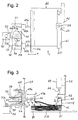
- Fig. 2 is a plan view showing the first sorting mechanism 40
- Fig. 3 is a side view seen in a direction of an arrow Y of Fig. 2.
- an inhibiting plate 41 is mounted on a fixing member 42 attached to the frame 59 of the first paper bundle receiving portion 33.
- An electromagnetic solenoid 45 is also attached to the frame 59.
- a lifting plate 43 is coupled to the electromagnetic solenoid 45 through a rod 44. The lifting plate 43 performs a lifting motion in a direction of an arrow Q by the operation of the electromagnetic solenoid 45.
- the reference numeral 48 denotes a supporting member fixed to the frame 59 of the first paper bundle receiving portion 33.
- First and second rods 47a and 47b are supported on the supporting member 48 through bearings 49a and 49b, respectively.
- the first and second rods 47a and 47b can reciprocate horizontally right and left with respect to the delivery direction of the paper bundles for the first paper bundle receiving portion 33.
- a movable plate 46 is coupled to the tips of the first and second rods 47a and 47b.
- a driving motor 50 is fixed to the frame of the first paper bundle receiving portion 33 and a first pulley 51a is fixed to the rotary shaft of the driving motor 50.
- a vertical rotary shaft 53 is attached to the supporting member 48, and a second pulley 51b is fixed to the lower end of the rotary shaft 53.
- a driving belt 52 is entrained between the first and second pulleys 51a and 51b.
- a lever 55 is swingably fixed onto the supporting member 48 around a supporting point 56.
- a driven cam 58 for a cam 54 attached to the rotary shaft 53 is fixed to the lever 55.
- a pin 57 provided in the rear end portion of the first rod 47a is engaged with a concave portion of the tip of the lever 55.
- the first pulley 51a is rotated so that the rotation of the first pulley 51a is transmitted to the second pulley 51b by means of the driving belt 52.
- the rotary shaft 53 is rotated by the rotation of the second pulley 51b so that the cam 54 is rotated in a direction shown by an arrow R.
- the lever 55 swings around the supporting point 56 in a direction shown by an arrow S so that the first rod 47a reciprocates through the pin 57 and the second rod 47b also reciprocates interlockingly.
- the movable plate 46 reciprocates in a direction shown by an arrow P (right and left with respect to the delivery direction of the paper bundle).
- the lifting plate 43 is lifted in a timing in which the movable plate 46 moves from a position a to a position b, one of ends of the delivered paper bundle A1 directly comes in contact with the inhibiting plate 41 and the other end directly comes in contact with the movable plate 46.
- the movable plate 46 is inverted to move from the position b to the position a, the paper bundle A1 is dropped onto the paper bundle mounting plate 21a.
- the lifting plate 43 goes downward and directly comes in contact with one of the ends of the paper bundle B1 which is delivered next.
- the other end of the paper bundle B1 directly comes in contact with the movable plate 46.
- the paper bundle B1 is dropped onto the paper bundle mounting plate 21a.
- the inverting operation of the movable plate 46 interlocks with the lifting operation of the lifting plate 43 so that the paper bundles sequentially delivered to the first paper bundle receiving portion 33 are alternately shifted right and left with respect to the delivery direction and are accumulated onto the paper bundle mounting plate 21a as shown in Fig. 4.
- the paper accumulating device 20 has a control portion 70 for controlling the actuation of the switching gate plate 26 and that of the sorting mechanisms 40 and 60 of the paper bundle receiving portions 33 and 34 and for controlling the paper discharging speed of the sheet collator 1.
- the paper bundles given from the paper discharging port 11 of the sheet collator 1 to the paper bundle feeding port 31 of the paper accumulating device 20 are sequentially fed.
- the paper bundles fed to the paper bundle feeding port 31 are introduced into the main delivery path portion 23.
- the control portion 70 actuates the switching gate plate 26 in such a manner that the main delivery path portion 23 is alternately connected to the first and second branch delivery path portions 24 and 25 each time the paper bundles are delivered before the paper bundles are completely accumulated in one of the first and second pallets 21 and 22. Consequently, the paper bundles are alternately delivered to the first and second paper bundle receiving portions 33 and 34 and the paper bundles are alternately accumulated onto the first and second pallets 21 and 22. In the meantime, the control portion 70 controls the operation of the switching gate plate 26 and that of the sorting mechanisms 40 and 60 of the paper bundle receiving portions 33 and 34 according to the delivery speed of the paper bundles and therefore the paper discharging speed of the sheet collator 1.
- the paper bundles sequentially fed from the sheet collator 1 are alternately sent to the two paper bundle receiving portions 33 and 34.
- the paper bundle receiving portions 33 and 34 the paper bundles which are sequentially delivered are alternately shifted right and left with respect to the delivery direction by means of the sorting mechanisms 40 and 60 and are then accumulated onto the pallets 21 and 22.
- the paper bundles can be delivered to one of the paper bundle receiving portions 33 and 34 while the sorting mechanisms 40 and 60 are actuated in the other paper bundle receiving portion 33 or 34.
- the paper bundles can be sorted at a high speed according to the paper discharging speed of the sheet collator 1 and can be accumulated onto the pallets 21 and 22.
- the next step of the bookbinding process can be performed rapidly.
- the switching gate plate 26 is actuated in such a manner that the paper bundles are delivered to only the other paper bundle receiving portion, that is, the second paper bundle receiving portion 34 till the first pallet 21 is exchanged for a new empty pallet and the paper discharging speed of the sheet collator 1 is lowered to be adapted to the operating speed of the sorting mechanism 60 of the second paper bundle receiving portion 34.
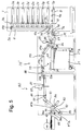
- Fig. 5 is a schematic side view showing a paper accumulating device according to another embodiment of the present invention.
- an apparatus 80 for stitching collated sheet bundles is connected to the second branch delivery path portions 25.
- the stitching apparatus 80 includes a sheet stitching station 81 and a sheet bending station 82 therein.
- a stitching head 83, a first stopper 84 for a sheet bundle to stitched along an center line thereof are installed.
- a third stopper 85, a fold knife 86 and a pair of fold rollers 87a, 87b are arranged.
- the stitching apparatus 80 further includes a transport path for transporting sheet bundles from a sheet supply inlet 88 to a sheet eject outlet 89.
- the sheet transport path is composed of a pair of feed rollers 93a, 93b, a first conveyor belt 84, a second conveyor belt 91, a third conveyor belt 92, the fold rollers 87a, 87b, a pair of guide plates 95, 95 and a pair of delivery rollers 94a, 94b.
Landscapes
- Forming Counted Batches (AREA)
- Separation, Sorting, Adjustment, Or Bending Of Sheets To Be Conveyed (AREA)
- Pile Receivers (AREA)
Applications Claiming Priority (2)
| Application Number | Priority Date | Filing Date | Title |
|---|---|---|---|
| JP21473898 | 1998-06-23 | ||
| JP10214738A JP2000007210A (ja) | 1998-06-23 | 1998-06-23 | 用紙集積装置 |
Publications (3)
| Publication Number | Publication Date |
|---|---|
| EP0967166A2 true EP0967166A2 (fr) | 1999-12-29 |
| EP0967166A3 EP0967166A3 (fr) | 2000-10-11 |
| EP0967166B1 EP0967166B1 (fr) | 2002-09-18 |
Family
ID=16660788
Family Applications (1)
| Application Number | Title | Priority Date | Filing Date |
|---|---|---|---|
| EP99250181A Expired - Lifetime EP0967166B1 (fr) | 1998-06-23 | 1999-06-10 | Dispositif pour collationner des feuilles |
Country Status (5)
| Country | Link |
|---|---|
| US (1) | US6234474B1 (fr) |
| EP (1) | EP0967166B1 (fr) |
| JP (1) | JP2000007210A (fr) |
| DE (1) | DE69902970T2 (fr) |
| DK (1) | DK0967166T3 (fr) |
Cited By (1)
| Publication number | Priority date | Publication date | Assignee | Title |
|---|---|---|---|---|
| EP1072549A3 (fr) * | 1999-07-26 | 2002-05-22 | Riso Kagaku Corporation | Dispositif collecteur |
Families Citing this family (10)
| Publication number | Priority date | Publication date | Assignee | Title |
|---|---|---|---|---|
| US6283472B1 (en) * | 2000-05-05 | 2001-09-04 | Sharp Laboratories Of America, Inc. | System for automatic disposal of canceled paper output |
| JP4096624B2 (ja) * | 2002-05-23 | 2008-06-04 | コニカミノルタホールディングス株式会社 | 用紙スタッカー |
| JP3733347B2 (ja) * | 2002-08-22 | 2006-01-11 | キヤノン株式会社 | シート処理装置 |
| JP4267044B2 (ja) * | 2006-09-06 | 2009-05-27 | キヤノン株式会社 | シート積載装置及び画像形成装置 |
| JP5213683B2 (ja) * | 2008-12-17 | 2013-06-19 | キヤノン株式会社 | シート処理装置、シート処理装置の制御方法、及びプログラム |
| US8567156B2 (en) * | 2009-06-15 | 2013-10-29 | Kabushiki Kaisha Toshiba | Paper sheet processing system |
| US8376361B2 (en) * | 2009-06-17 | 2013-02-19 | Xerox Corporation | Method and apparatus for printed media stack management in an image production device |
| JP6607995B2 (ja) * | 2018-05-08 | 2019-11-20 | 株式会社プレッシオ | 折込用広告束紙揃え搬送装置、及び折込用広告束紙揃え搬送装置付き丁合機 |
| JP7315322B2 (ja) * | 2018-12-27 | 2023-07-26 | 理想科学工業株式会社 | 媒体排出装置、及び、印刷システム |
| JP7372722B2 (ja) * | 2019-09-30 | 2023-11-01 | 理想科学工業株式会社 | 媒体排出装置、及び、印刷システム |
Family Cites Families (13)
| Publication number | Priority date | Publication date | Assignee | Title |
|---|---|---|---|---|
| US2697388A (en) * | 1951-05-21 | 1954-12-21 | Cutler Hammer Inc | System for stacking newspapers and the like |
| GB1167728A (en) * | 1965-12-23 | 1969-10-22 | Masson Scott Thrissell Eng Ltd | Improvements in Sheet-delivery Mechanisms |
| US4102253A (en) * | 1976-10-26 | 1978-07-25 | Gannicott David James H | Counting and stacking unit |
| US4373713A (en) * | 1980-12-24 | 1983-02-15 | Motter Printing Press Co. | Diverter mechanism |
| US4477218A (en) * | 1982-03-08 | 1984-10-16 | The Mead Corporation | Offset stacker and method |
| US4534552A (en) * | 1983-07-20 | 1985-08-13 | Motter Printing Press Co. | Sheet diverting system |
| JP2511075B2 (ja) * | 1987-11-11 | 1996-06-26 | 三菱重工業株式会社 | 輪転印刷機の折機 |
| US4926220A (en) | 1988-10-17 | 1990-05-15 | Xerox Corporation | Dual mode set delivery apparatus |
| US5293797A (en) * | 1989-12-22 | 1994-03-15 | John Brown, Inc. | Multiple point delivery apparatus for separating of sheet-like elements |
| US5188353A (en) * | 1990-08-17 | 1993-02-23 | Xerox Corporation | Disk stacker including tamping mechanism capable of cross-direction offsetting |
| DE4322324C2 (de) * | 1993-07-05 | 2002-01-17 | Heidelberger Druckmasch Ag | Bogentransport und Bogenführung im Auslagebereich von Rotationsdruckmaschinen |
| CA2172082A1 (fr) * | 1995-03-24 | 1996-09-25 | Carl R. Marschke | Deviateur-economiseur de tole, pour onduleuse |
| US5666630A (en) | 1996-06-03 | 1997-09-09 | Xerox Corporation | Unload while run apparatus for a copier/printer |
-
1998
- 1998-06-23 JP JP10214738A patent/JP2000007210A/ja active Pending
-
1999
- 1999-06-10 DE DE69902970T patent/DE69902970T2/de not_active Expired - Lifetime
- 1999-06-10 DK DK99250181T patent/DK0967166T3/da active
- 1999-06-10 EP EP99250181A patent/EP0967166B1/fr not_active Expired - Lifetime
- 1999-06-21 US US09/336,695 patent/US6234474B1/en not_active Expired - Fee Related
Cited By (1)
| Publication number | Priority date | Publication date | Assignee | Title |
|---|---|---|---|---|
| EP1072549A3 (fr) * | 1999-07-26 | 2002-05-22 | Riso Kagaku Corporation | Dispositif collecteur |
Also Published As
| Publication number | Publication date |
|---|---|
| JP2000007210A (ja) | 2000-01-11 |
| DE69902970T2 (de) | 2003-01-23 |
| DK0967166T3 (da) | 2002-10-14 |
| DE69902970D1 (de) | 2002-10-24 |
| EP0967166A3 (fr) | 2000-10-11 |
| EP0967166B1 (fr) | 2002-09-18 |
| US6234474B1 (en) | 2001-05-22 |
Similar Documents
| Publication | Publication Date | Title |
|---|---|---|
| JP6558875B2 (ja) | 製品流れで供給された印刷業製品を相互に別々の2つのスタックに排出する装置およびこれを用いて印刷業製品を排出するか又は積み降ろす方法 | |
| US6234474B1 (en) | Paper accumulating device | |
| JP2006264978A (ja) | 用紙後処理装置 | |
| JP5248786B2 (ja) | 立ち状態で前後に整列された印刷紙から積重ね体を形成する方法ならびにその方法を実施するための装置 | |
| US6991229B2 (en) | Paper stacker for use with image forming apparatus | |
| FI114457B (fi) | Laite setelipakettien valmistamiseksi setelinipuista | |
| EP0716999A1 (fr) | Dispositif et procédé utilisés pour l'alimentation d'assemblages de feuilles | |
| US20080211161A1 (en) | Sheet finishing apparatus | |
| US6234467B1 (en) | Apparatus for stacking and sorting printed documents and feeding them to a finishing machine | |
| CN106516855B (zh) | 片材处理装置和成像装置 | |
| US20070138731A1 (en) | Sheet post-processing apparatus | |
| JP5553430B2 (ja) | ブックブロック、本または同様の印刷物を製造するために印刷紙葉を供給する装置 | |
| US7654789B2 (en) | Apparatus for forming stacks with print products with ejection groove and lifting plates | |
| CN115210159B (zh) | 用于在转换机中存储片材堆的设备和转换机 | |
| JPH10305958A (ja) | シート後処理装置 | |
| JP4183848B2 (ja) | 用紙集積装置 | |
| US20050001373A1 (en) | Device and method for aligning a stack of sheets arranged one above the other | |
| CN100554114C (zh) | 折纸装置和纸后处理装置 | |
| JP2007308215A (ja) | 用紙後処理装置 | |
| JP4471207B2 (ja) | シート後処理装置 | |
| JP6191946B2 (ja) | シート収納装置及びこれを用いた後処理装置並びに画像形成システム | |
| JP3689459B2 (ja) | シート束スタック装置を備えるシート分類装置及び画像形成装置 | |
| EP0830303A1 (fr) | Alimentation d'un ensemble de feuilles de papier | |
| JPH0859017A (ja) | 製本用オートローダ | |
| JP2001348158A (ja) | 用紙集積装置及び用紙集積方法 |
Legal Events
| Date | Code | Title | Description |
|---|---|---|---|
| PUAI | Public reference made under article 153(3) epc to a published international application that has entered the european phase |
Free format text: ORIGINAL CODE: 0009012 |
|
| AK | Designated contracting states |
Kind code of ref document: A2 Designated state(s): BE CH DE DK FR GB IT LI SE |
|
| AX | Request for extension of the european patent |
Free format text: AL;LT;LV;MK;RO;SI |
|
| PUAL | Search report despatched |
Free format text: ORIGINAL CODE: 0009013 |
|
| AK | Designated contracting states |
Kind code of ref document: A3 Designated state(s): AT BE CH CY DE DK ES FI FR GB GR IE IT LI LU MC NL PT SE |
|
| AX | Request for extension of the european patent |
Free format text: AL;LT;LV;MK;RO;SI |
|
| 17P | Request for examination filed |
Effective date: 20001006 |
|
| 17Q | First examination report despatched |
Effective date: 20001214 |
|
| AKX | Designation fees paid |
Free format text: BE CH DE DK FR GB IT LI SE |
|
| GRAG | Despatch of communication of intention to grant |
Free format text: ORIGINAL CODE: EPIDOS AGRA |
|
| GRAG | Despatch of communication of intention to grant |
Free format text: ORIGINAL CODE: EPIDOS AGRA |
|
| GRAG | Despatch of communication of intention to grant |
Free format text: ORIGINAL CODE: EPIDOS AGRA |
|
| GRAH | Despatch of communication of intention to grant a patent |
Free format text: ORIGINAL CODE: EPIDOS IGRA |
|
| GRAH | Despatch of communication of intention to grant a patent |
Free format text: ORIGINAL CODE: EPIDOS IGRA |
|
| GRAA | (expected) grant |
Free format text: ORIGINAL CODE: 0009210 |
|
| AK | Designated contracting states |
Kind code of ref document: B1 Designated state(s): BE CH DE DK FR GB IT LI SE |
|
| REG | Reference to a national code |
Ref country code: GB Ref legal event code: FG4D |
|
| REG | Reference to a national code |
Ref country code: CH Ref legal event code: EP |
|
| REG | Reference to a national code |
Ref country code: DK Ref legal event code: T3 |
|
| REG | Reference to a national code |
Ref country code: CH Ref legal event code: NV Representative=s name: TROESCH SCHEIDEGGER WERNER AG |
|
| REF | Corresponds to: |
Ref document number: 69902970 Country of ref document: DE Date of ref document: 20021024 |
|
| ET | Fr: translation filed | ||
| PLBE | No opposition filed within time limit |
Free format text: ORIGINAL CODE: 0009261 |
|
| STAA | Information on the status of an ep patent application or granted ep patent |
Free format text: STATUS: NO OPPOSITION FILED WITHIN TIME LIMIT |
|
| 26N | No opposition filed |
Effective date: 20030619 |
|
| PGFP | Annual fee paid to national office [announced via postgrant information from national office to epo] |
Ref country code: DK Payment date: 20090611 Year of fee payment: 11 |
|
| PGFP | Annual fee paid to national office [announced via postgrant information from national office to epo] |
Ref country code: SE Payment date: 20090612 Year of fee payment: 11 Ref country code: IT Payment date: 20090624 Year of fee payment: 11 |
|
| PGFP | Annual fee paid to national office [announced via postgrant information from national office to epo] |
Ref country code: CH Payment date: 20090617 Year of fee payment: 11 |
|
| PGFP | Annual fee paid to national office [announced via postgrant information from national office to epo] |
Ref country code: BE Payment date: 20090715 Year of fee payment: 11 |
|
| BERE | Be: lapsed |
Owner name: *HORIZON INTERNATIONAL INC. Effective date: 20100630 |
|
| REG | Reference to a national code |
Ref country code: CH Ref legal event code: PL Ref country code: DK Ref legal event code: EBP |
|
| EUG | Se: european patent has lapsed | ||
| PG25 | Lapsed in a contracting state [announced via postgrant information from national office to epo] |
Ref country code: IT Free format text: LAPSE BECAUSE OF NON-PAYMENT OF DUE FEES Effective date: 20100610 |
|
| PG25 | Lapsed in a contracting state [announced via postgrant information from national office to epo] |
Ref country code: LI Free format text: LAPSE BECAUSE OF NON-PAYMENT OF DUE FEES Effective date: 20100630 Ref country code: CH Free format text: LAPSE BECAUSE OF NON-PAYMENT OF DUE FEES Effective date: 20100630 |
|
| PG25 | Lapsed in a contracting state [announced via postgrant information from national office to epo] |
Ref country code: BE Free format text: LAPSE BECAUSE OF NON-PAYMENT OF DUE FEES Effective date: 20100630 |
|
| PG25 | Lapsed in a contracting state [announced via postgrant information from national office to epo] |
Ref country code: DK Free format text: LAPSE BECAUSE OF NON-PAYMENT OF DUE FEES Effective date: 20100630 |
|
| PG25 | Lapsed in a contracting state [announced via postgrant information from national office to epo] |
Ref country code: SE Free format text: LAPSE BECAUSE OF NON-PAYMENT OF DUE FEES Effective date: 20100611 |
|
| PGFP | Annual fee paid to national office [announced via postgrant information from national office to epo] |
Ref country code: DE Payment date: 20130620 Year of fee payment: 15 Ref country code: GB Payment date: 20130619 Year of fee payment: 15 |
|
| PGFP | Annual fee paid to national office [announced via postgrant information from national office to epo] |
Ref country code: FR Payment date: 20130703 Year of fee payment: 15 |
|
| REG | Reference to a national code |
Ref country code: DE Ref legal event code: R119 Ref document number: 69902970 Country of ref document: DE |
|
| GBPC | Gb: european patent ceased through non-payment of renewal fee |
Effective date: 20140610 |
|
| REG | Reference to a national code |
Ref country code: FR Ref legal event code: ST Effective date: 20150227 |
|
| REG | Reference to a national code |
Ref country code: DE Ref legal event code: R119 Ref document number: 69902970 Country of ref document: DE Effective date: 20150101 |
|
| PG25 | Lapsed in a contracting state [announced via postgrant information from national office to epo] |
Ref country code: DE Free format text: LAPSE BECAUSE OF NON-PAYMENT OF DUE FEES Effective date: 20150101 |
|
| PG25 | Lapsed in a contracting state [announced via postgrant information from national office to epo] |
Ref country code: FR Free format text: LAPSE BECAUSE OF NON-PAYMENT OF DUE FEES Effective date: 20140630 Ref country code: GB Free format text: LAPSE BECAUSE OF NON-PAYMENT OF DUE FEES Effective date: 20140610 |