EP0967167A1 - Dispositif de transport de cahiers de feuilles, en particulier dispositif de pliage ainsi qu'une méthode de transport de cahier de feuilles, en particulier méthode de formation du pli - Google Patents
Dispositif de transport de cahiers de feuilles, en particulier dispositif de pliage ainsi qu'une méthode de transport de cahier de feuilles, en particulier méthode de formation du pli Download PDFInfo
- Publication number
- EP0967167A1 EP0967167A1 EP99111206A EP99111206A EP0967167A1 EP 0967167 A1 EP0967167 A1 EP 0967167A1 EP 99111206 A EP99111206 A EP 99111206A EP 99111206 A EP99111206 A EP 99111206A EP 0967167 A1 EP0967167 A1 EP 0967167A1
- Authority
- EP
- European Patent Office
- Prior art keywords
- conveyor
- engagement
- folding
- press
- level
- Prior art date
- Legal status (The legal status is an assumption and is not a legal conclusion. Google has not performed a legal analysis and makes no representation as to the accuracy of the status listed.)
- Granted
Links
- 238000000034 method Methods 0.000 title claims description 11
- 238000003825 pressing Methods 0.000 claims description 21
- 238000006073 displacement reaction Methods 0.000 claims description 4
- 230000001360 synchronised effect Effects 0.000 claims description 3
- 210000000080 chela (arthropods) Anatomy 0.000 claims 1
- 210000002414 leg Anatomy 0.000 description 14
- 230000005540 biological transmission Effects 0.000 description 7
- 238000012549 training Methods 0.000 description 6
- 230000001154 acute effect Effects 0.000 description 4
- 210000000056 organ Anatomy 0.000 description 4
- 238000011144 upstream manufacturing Methods 0.000 description 3
- 230000000694 effects Effects 0.000 description 2
- 210000003414 extremity Anatomy 0.000 description 2
- 238000012546 transfer Methods 0.000 description 2
- 208000034656 Contusions Diseases 0.000 description 1
- 238000013459 approach Methods 0.000 description 1
- 230000009286 beneficial effect Effects 0.000 description 1
- 230000015572 biosynthetic process Effects 0.000 description 1
- 239000000969 carrier Substances 0.000 description 1
- 210000001520 comb Anatomy 0.000 description 1
- 230000006835 compression Effects 0.000 description 1
- 238000007906 compression Methods 0.000 description 1
- 230000008878 coupling Effects 0.000 description 1
- 238000010168 coupling process Methods 0.000 description 1
- 238000005859 coupling reaction Methods 0.000 description 1
- 238000005520 cutting process Methods 0.000 description 1
- 238000013016 damping Methods 0.000 description 1
- 230000007423 decrease Effects 0.000 description 1
- 239000000945 filler Substances 0.000 description 1
- 210000003127 knee Anatomy 0.000 description 1
- 239000002184 metal Substances 0.000 description 1
- 230000000149 penetrating effect Effects 0.000 description 1
- 238000005096 rolling process Methods 0.000 description 1
- 238000004904 shortening Methods 0.000 description 1
- 230000007704 transition Effects 0.000 description 1
Images


Classifications
-
- B—PERFORMING OPERATIONS; TRANSPORTING
- B65—CONVEYING; PACKING; STORING; HANDLING THIN OR FILAMENTARY MATERIAL
- B65H—HANDLING THIN OR FILAMENTARY MATERIAL, e.g. SHEETS, WEBS, CABLES
- B65H45/00—Folding thin material
- B65H45/12—Folding articles or webs with application of pressure to define or form crease lines
- B65H45/18—Oscillating or reciprocating blade folders
Definitions
- the invention relates to a device according to the preamble of claim 1 and a method according to the preamble of Claim 7.
- They are for transporting sheet layers suitable, e.g. contiguous over a connection, like an edge connection, hereinafter called fold, with each other are directly connected.
- the sheet layers like paper, then lie against each other with their inner sides and form an outside with facing outer surfaces. If folded, the insides go over the concave Inside of the fold and the outer surfaces over the convex curved outside of the fold in one piece.
- the sheet layers can be on either side of the connection or be multilayer on this.
- the inside is then through the innermost layer and the outsides through the outermost Location formed. In between there are other layers.
- Such too folding or folded sheet stacks are e.g. to exercise books processed further.
- DE-PS 25 19 420 is a transport and folding device become known, on their characteristics and effects for inclusion in the present invention becomes. With it, even thicker sheets can be stacked without the risk internal bruises at high speed and easy Structure to be folded.
- the invention has for its object a device or to create a process by which disadvantages known training or the type described avoided are. Furthermore, the sheet layer from the engagement member should subtracted less friction or the working speed can be increased.
- means are provided by which the Sheet position is passed to the conveyor so that its on the lateral force acting on the outside is not or only insignificantly or is negligibly transmitted to the engaging member.
- This transverse force expediently acts on everyone Sheet layers so clamping that they are not against each other can move under the conveying force, their direction across to the lateral force.
- the leaf layers are by themselves frictional engagement transported to the outside. The transfer of the frictional pressure to the contact between Leaf position and engaging member is significantly reduced or canceled.
- the force attack for feeding the sheet layer into the conveying engagement can be in the area of an opening or break of the engaging member also upstream from the conveyor on the Outside.
- this opening is useful on End of the engagement member as an open cutout in the Area provided in which the conveyor is in the outside the sheet layer engages.
- the conveyor presses the Sheet layers with their insides in the opening immediately against each other and not against the engaging member.
- openings can be made before or upon reaching the conveyor the engaging member is closed with filler pieces or to be filled out. This is the end of the engagement member initially also in the respective later opening area the inside of the fold. This is particularly useful if with the engagement member or folding sword The inside of the fold or crease is continuous and even is formed. Before reaching the conveyor, the Completion of the opening removed or withdrawn. Thereby it remains outside the narrowest area of the mouth of the conveyor gap, but can be funnel-shaped Protrude into this gap.
- the training according to the invention is useful everywhere where leaf layers are reduced from one engagement member under Friction should be deducted. Regardless of the one described Training is also beneficial to one like the sponsor pressing and running on the outside of the sheet layer training the attacking member so that its in transport or Direction of the foremost area the greatest pressing force exercises. Immediately following areas of the Pressing surface exert a lower pressing force, e.g. while the pressing surface rolls on the outer surface of the sheet layer.
- the Transverse displacement of the conveyor, the pressing surfaces or the like electronic, hydraulic or pneumatic Control means conceivable, but mechanical are expedient Control means provided.
- These can be a cam control include. Those guided on the cam or cam bodies Runners are connected to each other via transmission drives controlling link connected to the drive.
- the transmission drive can include levers or push and pull rods with joints or only be formed by such.
- the sheet layer with the engaging member and / or the Press member to pass to the conveyor, the engaging member but not subject to the contact pressure of the conveyor.
- the device 1 is used for fully automated implementation of the method according to the invention.
- a sheet layer is like a stack of ten or more papers sheets on top of each other, forming a fold 3 folded over 180 °.
- the two fold legs of the same size then lie against each other with their inside surfaces and merge into each other via the inside 4 of the fold 3, so that they form outer sides 5 facing away from each other.
- At the fold becomes the layer 2 perpendicular to its spread Level 10 in the direction 6 or 16 compared to a stationary one Device rack 7 from a table 8 at right angles moved away.
- the upper table surface is the spread, flat layer 2 parallel to level 10 by means of funding supplied that the fold zone congruent with the Table 8 penetrating gap 9 is.
- this layer 2 of the table surface 10 in the area of Fold zone lifted vertically upwards.
- the fold 3 and the Layer legs are then symmetrical to or on both sides of the Folding plane 11, which is perpendicular to plane 10.
- the one to fold 3 parallel length of layer 2 is multi-use, i.e. around a Many times larger than the booklets to be produced. After this The layer 2 is folded and removed by cross-sections in divided the individual booklets or the like.
- Level 10 Parallel level 12, in which the outer sides 5 for the further transport in direction 6 or 16 can be detected.
- a level 13 that is at least as far as level 12 or slightly further from level 10 the inside 4 by pressure directly in the direction 16 charged.
- a level 14 which closer to level 10 than levels 12, 13 which Layer legs parallel at a short distance from each other held.
- Levels 10 and 12 to 14 are parallel.
- the fold 3 or the directly on it subsequent layer legs pressed.
- the Layer legs in the press area up to the inside 4 and over their entire length continuously spaced from each other held.
- the pressure against level 11 is carried out in one pass in direction 6 through level 15.
- the glide Lay leg under curve on the table surface and lift until they are level.
- the pressing is finished shortly before the fold 3 reaches one of the parallel planes 12 to 15.
- the Layer legs are then free from the pressing contact.
- the Pressing is carried out only via a smaller area of the height of the ply legs and during these still touch level 10. This also applies to that Reach levels 12 to 13.
- the maximum pressing from level 12 and across to level 11 Funding intervention takes place only in sections of the length of the Layer 2. These sections are shorter than the ones in between lying longitudinal sections in which the pressure of the conveyor intervention on the other hand, it is reduced or completely avoided. in the Area of these longitudinal sections touch the inside the layer leg therefore until level 12 or 13 not, but only immediately afterwards. While the Pressure between and at a distance from both levels 10, 14 by an arc movement in the direction 18 across the planes 10 and 12 to 14, the fold pressure of the layer 2 between levels 12 to 14 by moving in the direction 19 transversely to level 11.
- the direction 19 can be parallel to levels 10 and 12 to 14 or in an arch path lie, which are steeper than the direction of level 11 18 is.
- a plate-shaped engagement member or folding sword 20 is provided. It is in the Level 11, in the starting position completely below level 10 and is then moved through the gap 9 in the direction 16. Here it is on the lateral boundary surfaces of the gap 9th and table 8 slidably guided. Here it lies above the entire length on the inside 4 with one on both sides end edge flanked at an oblique and acute angle.
- the sword 20 promotes the situation 2 through the press 22 and up to Level 14.
- the sword 20 is in two combs or sub-members 23, 24 of equal length. They have between levels 10 and 12 to 14 same cross sections and are always on the same level.
- Each sub-member 23, 24 consists of next to each other at a distance lying arms or strips of sheet metal that point towards 6, 16 protrude freely up to their pointed ends 25 or 26. Both side edges of each link 24 facing away from one another are on two mutually facing side edges of two neighboring Links 23 slidably guided. The same width among themselves the arm 23 is twice as large or larger than that of each other equal width of each of the arms 24. The two laterally outermost arms 23 are opposite the other arms 23, 24 narrower.
- the end edges 26 of all lie up to level 14 Links 24 in a line with and immediately after to the also rectilinear end edges 25 of all links 23. Then the links 24 stop moving in the direction 16, while the links 23 to level 12 or 13 in the direction 16 continue to run.
- the Carriages 28, 29 lie below level 10 or table 8.
- the carriage 28 is on a linear guide 31 of the frame 7 in the direction 16 to and fro stored.
- the carriage 29 is on a linear guide 32 of the carriage 28 reciprocating in the same direction 16 slidably guided.
- the slides 28, 29 are common and independently of one another in and against direction 16 displaceable, whereby the position control of the ends 25, 26 is effected.
- the upper end of the guide 31 can Wear table 8.
- the transporter 21 has a position 2 for the entry mouth 33 constantly widened in the direction of 6. It extends between level 10 and level 12 or 14. In level 12, the narrowest area of the mouth 33 reached. It is bounded by driving surfaces 34 which are in Run towards 6 and frictionally into the outside 5 intervene only in the area of the mentioned sections. In Direction 6 from level 12 these surfaces 34 limit one Constantly wide, but elastically expandable conveyor gap 35 for the position 2.
- the mouth 33 is up to level 12 from circular deflections lying on both sides of level 11, flanked like rollers 36, each over an endless Conveyor belt 37 rotates continuously. The bands 37 limit this Mouth 33 and with the surfaces 34 the gap 35.
- the opposing rollers 36 are on separate Carriers 38 suspended rotatably, which on both sides of the Level 11 can be pivoted about separate axes 39 in the direction 19 are. The distance between these most posed as well as above the axis 39 of the roller axes is always larger than the distance between the roller axes.
- One each Conveying gap 33 to 35 lies in the area of an arm 24 or the associated gap 27.
- On each side of level 11 are the holder 38 of all rollers 36 along the same axis 39 and attached rotatably adjustable.
- Opposing beams 38 or axes 39 are directly opposed to each other connected to the drive. This drive connection 40 can be form-fitting, e.g. by two arranged on the axes 39, equally large gears are formed.
- the press 22 has one on each side of the level 11 plate or strip-shaped ram 41.
- Everyone Stamp 41 forms with its edge surface closest to level 11 a convexly curved pressing surface 42. It goes over the total working width of the device 1 or 20 or 21 or 22 continuously through and is like the stamp 41 always in Distance from levels 10 and 12 to 14.
- the end edges of each Stamps 41 are movably attached to two supports 43, which in turn is arranged on an axis or shaft 46 are.
- the axes 46 are equidistant from the plane 11 and lie in the level 15 in the middle between the Levels 10, 14.
- Each axis 46 lies in the central plane of the associated surface 42 or plate 41 and at a distance behind the longitudinal edge facing away from surface 42 Plate 41.
- the surfaces 42 lie with Distance from and between levels 10, 15 and in the end position at a distance from and between levels 12 to 14 and 15.
- the foremost end and longitudinal edge 47 in direction 18 each surface 42 describes the movement between the two positions around the axis 45 an arc path 17, of which is the upstream surface areas 42 are permanently set back.
- Form in the starting position therefore the surfaces 42 a funnel-shaped up to these edges 47 narrowed mouth for the fold 3, which is at a distance of and is immediately adjacent to level 10.
- the transport of the unfolded layers 2 over the withdrawn Sword 20 and all movements described and the Removal are synchronized by a controller 30 and like this powered by a common motor.
- the Control 30 points below the table 8 and laterally adjacent to level 11, a camshaft 48 and above lying and further away from level 11 a control shaft 49 on. Circumferential cams are rotatably fixed on the rotatable shaft 48 50 to 52 and 54 arranged.
- On the other side of the Level 11 is one in height between the waves 48, 49 Intermediate shaft 53 to limit the stroke of the links 24 to provided for level 14.
- the facilities 20 to 21 will be controlled by the cams moved via a linkage 55.
- Levers are fixed on the shaft 49 in a rotationally fixed manner 56 arranged, which protrude freely in the direction of level 11.
- Rod 57 At the end of each lever 56 is one perpendicular to level 10 Rod 57 with its lower end pivoted, the upper end articulated to the underside of the carriage 28 is.
- rod 57 on each Transmission link 56 a rod in the form of a toggle lever 58 hinged, the upper end of which is at the bottom of the carriage 29 or above is pivoted.
- the stretched Position namely in the stroke up to approximately level 14 also both knee arms of lever 58 at right angles to level 10. With one adjoining the rod 58 facing away from the plane 11 Control member, such as a rod 59, the effective length of rod 58 changed.
- the cam plate 50 is used to jointly pivot the Wave 49 and transmission organs 56 to 59, 69, for what you run a runner 60.
- a corresponding runner 61 is guided on the cam 51 to the conveyor 21 Intermediate organs 71, 65, 67, 39, 38 to operate.
- a runner 62 is guided to the press 22nd to operate via intermediate organs 72, 66, 68, 46, 43.
- a runner 64 is guided on the cam disk 54 in order to the carriage 29 via transmission members 74, 75, 63, 59, 58 to operate or the sled 28, 29 or the partial links 23, 24 to move against each other.
- the pontics include an obtuse-angled angle lever arranged on the axis 53 63, on its upward arm the rod 59 is articulated. In the middle between its two end positions the effective axial plane of this arm is at right angles to level 10.
- the rotor 60 is mounted on the free end of a lever 70, which, like the lever 56, is arranged on the shaft 49 in a rotationally fixed manner is.
- the runners 61, 62, 64 are each on an associated Lever 71, 72, 74 mounted, which in turn is rotatable on the Shaft 49 is mounted.
- All levers 70 to 72, 74 project from the shaft 49 against level 11.
- the effective axial plane of each of these Lever and the lever 56 is in the associated middle position perpendicular to level 11. All levers are independent from each other downwards or against the corresponding cam Springs 73 spring-loaded.
- lever 71 On the lever 71 is an acute angle to the plane 11 Rod 65 articulated with its lower end. It prevails level 10 and is at its upper end on a lever 67 articulated, which is directed away from level 11 of the shaft 39 which is arranged on that of the Waves 48, 49 facing away from level 11.
- the effective axial plane of this lever 67 is in the central position of the pliers 21 at right angles to level 11.
- the rotor 61 lies between the lower linkage of the rod 65 and the Wave 49.
- Each lever 68 is firmly seated on the associated shaft 46 and protrudes freely against level 11. In the middle position mentioned the press 22, the levers 68 are at right angles to the Level 11. The axis of the joint between rod 66 and lever 68 lies below the central plane parallel to it Surface 42 and in a parallel and common to level 11 Axial plane with the associated deflection 36, if this 2 and 3 is closest to level 11.
- the axis of each of the rotating bodies or joints 36, 38 to 41, 43, 46, 48 to 54 and 56 to 75 are parallel to the Levels 10 and 11.
- the axes of the shafts 39, 46, 48, 49, 53 are permanently provided on frame 7.
- the device 1 works according to the following method:
- the shaft 48 with the non-rotatably arranged cams 50 to 52, 54 continuously rotates according to FIGS. 1 and 2 Clockwise towards 76. This will make the sled 28, 29 with the sword parts 23, 24 reversing over a adjustable stroke between their upper and lower end positions with constantly changing speeds back and forth moved.
- Below the level 14 are the ends 25, 26 or the tops of the slides 28, 29 always on aligned at the same height.
- the press 22 lowered to its starting position. She achieves this when the sword 20 has reached its lower turning point or shortly after it started moving upwards. in the mouth 33 begins at the same moment or shortly before to open.
- the lever 58 is in its extended position, so that the edges 25, 26 are aligned.
- the spread layer 2 is over him fed and immediately detected by the edge 25, 26.
- the layer 2 is forming the fold 3 up to the area of the surfaces 42 still standing in the initial position, which in the upper end position according to FIG. 3 the transition forms between the inlet and the outlet mouth.
- This The area is closer to the edge 47 than from the lower end of the Areas 42. The areas run when this area is reached 42 in sync with the fold 3 and roll it against the sloping flanks of the ends 25, 26.
- the center position of the stamp 41 takes the rolling pressure of the surfaces 42 continuously up to their upper end position until they detach completely from the layer legs and from the aligned ends 25, 26 are run through. In this Position the surfaces 42 until the explained return stroke of the sword 20 held continuously.
- the upward movement of the sword 20 is faster than in the first stroke part while the ends 25, 26 pass through the press 22 and then faster again.
- the shortening can be similar lever 58 at the beginning be faster than towards the end.
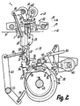
- the Coordination of the movements is based on the curve shapes Fig. 2 can be seen.
- the control of the relative movement of the slide 29 without possibly conceivable elastic stops causes a damping of Mass forces, so that even at high running speed low-impact and low-vibration work is guaranteed. It Up to a hundred or more folds or Lift cycles or full rotations of the shaft 48 are carried out.
- 11 or one to levels 10, 11th right-angled mid-plane symmetrical formation of many Parts these can be placed equally on both sides of the plane 11 can be used optionally. This applies e.g. for the units 36, 38, 39, the units 41 to 45 or their separate reference numerals provided for or Bars 66.
- the entire control 30 is space-saving below of the table 8 provided so that the level 10 only from the rods 65, 66 is penetrated upwards.
- a device 77 is provided, through which a Avoid overloading the device 1 or for adjustment Control connections can be interrupted.
- the facility 77 forms a disengageable drive connection or Coupling between the unit 60, 70 on the one hand and the Linkage 55 and the levers 56 on the other hand.
- On the on the Axis 49 rotatably mounted lever 70 is between the rotor 60 and the axis 49 a driver 78 or a pawl pivoted mounted in a counter member 79 in the sense of Lifting movement of the sword 20 engages entrainment.
- the Intervention is form-fitting, but in such a way that it is exceeded a predetermined driving force against a spring force disengages by itself.
- the counter member 79 is mounted on the axis 49 or lever non-rotatably connected to lever 56, which protrudes freely to level 11 and driver 78.
- Driver 78 is due to the shorter, downward Arm formed by a two-armed lever, the top of which directed longer arm with an actuator one Controller 80 is connected.
- the controller 80 With the controller 80, the Tripping force of the device 77 or the spring force mentioned can be changed continuously.
- the control rod 80 e.g. With a pneumatic cylinder with the same axis as it or its Piston rod connected, so the clutch 77 can also be arbitrarily engaged and disengaged. That cylinder or drive is attached to a carrier or pivotable stored, which on the axis 49 or on their bearings is arranged.
Landscapes
- Folding Of Thin Sheet-Like Materials, Special Discharging Devices, And Others (AREA)
- Making Paper Articles (AREA)
Applications Claiming Priority (2)
| Application Number | Priority Date | Filing Date | Title |
|---|---|---|---|
| DE19828300A DE19828300A1 (de) | 1998-06-25 | 1998-06-25 | Transportvorrichtung für Blattlagen, insbesondere Falzvorrichtung, sowie Verfahren zum Transportieren von Blattlagen, insbesondere zum Herstellen des Falzes |
| DE19828300 | 1998-06-25 |
Publications (2)
| Publication Number | Publication Date |
|---|---|
| EP0967167A1 true EP0967167A1 (fr) | 1999-12-29 |
| EP0967167B1 EP0967167B1 (fr) | 2003-09-03 |
Family
ID=7871969
Family Applications (1)
| Application Number | Title | Priority Date | Filing Date |
|---|---|---|---|
| EP99111206A Expired - Lifetime EP0967167B1 (fr) | 1998-06-25 | 1999-06-09 | Dispositif de transport de cahiers de feuilles, en particulier dispositif de pliage ainsi qu'une méthode de transport de cahier de feuilles, en particulier méthode de formation du pli |
Country Status (5)
| Country | Link |
|---|---|
| US (1) | US6511407B2 (fr) |
| EP (1) | EP0967167B1 (fr) |
| JP (1) | JP2000026020A (fr) |
| AT (1) | ATE248764T1 (fr) |
| DE (2) | DE19828300A1 (fr) |
Cited By (2)
| Publication number | Priority date | Publication date | Assignee | Title |
|---|---|---|---|---|
| EP1277687A3 (fr) * | 2001-07-16 | 2004-05-12 | Juan Marce Mias | Appareil de pliage pour formats de papier pliés |
| CN102267649A (zh) * | 2010-06-02 | 2011-12-07 | 株式会社理光 | 折页装置 |
Families Citing this family (5)
| Publication number | Priority date | Publication date | Assignee | Title |
|---|---|---|---|---|
| US6981938B2 (en) * | 2003-08-15 | 2006-01-03 | Xerox Corporation | Booklet maker with crease rolls having a slip clutch |
| US7798950B2 (en) * | 2007-11-27 | 2010-09-21 | Ricoh Company, Limited | Sheet finisher, image forming apparatus, and sheet processing method |
| US20110218092A1 (en) * | 2010-03-05 | 2011-09-08 | Kabushiki Kaisha Toshiba | Sheet folding mechanism, sheet post-processing apparatus and method thereof |
| JP5640757B2 (ja) * | 2011-01-18 | 2014-12-17 | 株式会社リコー | シート折り装置及び画像形成システム |
| JP6146650B2 (ja) * | 2013-01-28 | 2017-06-14 | 株式会社リコー | シート処理装置及び画像形成システム |
Citations (5)
| Publication number | Priority date | Publication date | Assignee | Title |
|---|---|---|---|---|
| DE365688C (de) * | 1920-11-02 | 1922-12-20 | Gandenbergersche Maschinenfabr | Falzvorrichtung fuer Druckmaschinen |
| US1693147A (en) * | 1927-07-01 | 1928-11-27 | Chambers Brothers Co | Sheet folding |
| DE2519420A1 (de) * | 1975-04-30 | 1977-01-20 | Bielomatik Leuze & Co | Falzvorrichtung |
| EP0371893A1 (fr) * | 1988-12-01 | 1990-06-06 | Louis Marion | Procédé et dispositif de pliage de bandes de matériaux textiles notamment de compresses |
| EP0498168A1 (fr) * | 1991-01-18 | 1992-08-12 | Eastman Kodak Company | Dispositif pour pliage de feuilles |
Family Cites Families (7)
| Publication number | Priority date | Publication date | Assignee | Title |
|---|---|---|---|---|
| GB1208728A (en) | 1966-12-19 | 1970-10-14 | Weir Henry J | Laundry folding device |
| FR2262593B1 (fr) | 1974-02-28 | 1976-12-10 | Martin Sa | |
| DD114580A1 (fr) * | 1974-03-07 | 1975-08-12 | ||
| FR2412485A2 (fr) * | 1977-12-26 | 1979-07-20 | Duflot Rene | Machine a plier des nappes de tissu, telles que des draps |
| FR2497782B1 (fr) | 1981-01-09 | 1985-08-02 | Mabotex | Machine automatique de coupe, de pliage et de conditionnement des feuilles de materiaux souples, debitees en bandes enroulees |
| EP0612879B1 (fr) | 1993-02-18 | 1995-02-08 | Jensen Ag Burgdorf | Appareil de pliage automatique de pièces de linge |
| JP2786617B2 (ja) | 1996-05-16 | 1998-08-13 | 三菱重工業株式会社 | 折機のシート等の搬送装置 |
-
1998
- 1998-06-25 DE DE19828300A patent/DE19828300A1/de not_active Withdrawn
-
1999
- 1999-06-09 EP EP99111206A patent/EP0967167B1/fr not_active Expired - Lifetime
- 1999-06-09 AT AT99111206T patent/ATE248764T1/de not_active IP Right Cessation
- 1999-06-09 DE DE59906825T patent/DE59906825D1/de not_active Expired - Fee Related
- 1999-06-23 JP JP11177236A patent/JP2000026020A/ja active Pending
-
2001
- 2001-09-10 US US09/950,260 patent/US6511407B2/en not_active Expired - Fee Related
Patent Citations (5)
| Publication number | Priority date | Publication date | Assignee | Title |
|---|---|---|---|---|
| DE365688C (de) * | 1920-11-02 | 1922-12-20 | Gandenbergersche Maschinenfabr | Falzvorrichtung fuer Druckmaschinen |
| US1693147A (en) * | 1927-07-01 | 1928-11-27 | Chambers Brothers Co | Sheet folding |
| DE2519420A1 (de) * | 1975-04-30 | 1977-01-20 | Bielomatik Leuze & Co | Falzvorrichtung |
| EP0371893A1 (fr) * | 1988-12-01 | 1990-06-06 | Louis Marion | Procédé et dispositif de pliage de bandes de matériaux textiles notamment de compresses |
| EP0498168A1 (fr) * | 1991-01-18 | 1992-08-12 | Eastman Kodak Company | Dispositif pour pliage de feuilles |
Cited By (3)
| Publication number | Priority date | Publication date | Assignee | Title |
|---|---|---|---|---|
| EP1277687A3 (fr) * | 2001-07-16 | 2004-05-12 | Juan Marce Mias | Appareil de pliage pour formats de papier pliés |
| CN102267649A (zh) * | 2010-06-02 | 2011-12-07 | 株式会社理光 | 折页装置 |
| CN102267649B (zh) * | 2010-06-02 | 2014-03-26 | 株式会社理光 | 折页装置 |
Also Published As
| Publication number | Publication date |
|---|---|
| JP2000026020A (ja) | 2000-01-25 |
| DE59906825D1 (de) | 2003-10-09 |
| ATE248764T1 (de) | 2003-09-15 |
| US6511407B2 (en) | 2003-01-28 |
| US20020082151A1 (en) | 2002-06-27 |
| EP0967167B1 (fr) | 2003-09-03 |
| DE19828300A1 (de) | 1999-12-30 |
Similar Documents
| Publication | Publication Date | Title |
|---|---|---|
| EP1163179B1 (fr) | Dispositif d'introduction pour bandes de papier | |
| DE19814917A1 (de) | Anlage zum Falten eines Textilbahnabschnitts | |
| DE19519707A1 (de) | Vorrichtung zur Bildung von Stapeln | |
| DE4211219C2 (de) | Anordnung zur Handhabung von Flachmaterial | |
| DE69208592T2 (de) | Verfahren und Vorrichtung zum Öffnen eines selbstschliessenden Greifers eines Greiferförderers | |
| EP0522319A1 (fr) | Procédé et dispositif pour ouvrir des articles flexible pliés hors du centre | |
| EP0967167B1 (fr) | Dispositif de transport de cahiers de feuilles, en particulier dispositif de pliage ainsi qu'une méthode de transport de cahier de feuilles, en particulier méthode de formation du pli | |
| DE2335358C3 (de) | Automatische Maschine zum Transport und Aufnähen der Signaturen in Büchern | |
| DE1704700A1 (de) | Vorrichtung zum biaxialen Strecken von Filmmaterial | |
| DE60318360T2 (de) | Rill- und Falzmaschine für Kartonplatten | |
| DE2214656C2 (de) | Vorrichtung zum Überführen eines Eingangsstromes aus aneinander anliegenden Gegenständen in einen Ausgangsstrom unter Abstand aufeinanderfolgender Gegenstände | |
| DE1561141B2 (de) | Vorrichtung zum einfuehren von beilagen in gefaltete druckerzeugnisse | |
| EP1334940B1 (fr) | Dispositif de pliage longitudinal | |
| DE2519420A1 (de) | Falzvorrichtung | |
| EP1398141A2 (fr) | Machine a plier | |
| EP2102085B1 (fr) | Dispositif de transport | |
| DE7824283U1 (de) | Automatische entnahmevorrichtung fuer eine zusammentragevorrichtung | |
| DE4407375A1 (de) | Falteinrichtung für Blattlagen | |
| DE2950553C2 (de) | Maschine zum Herstellen und Füllen von Säcken | |
| EP0207271B1 (fr) | Dispositif pour comprimer le pli d'articles imprimés transportés sur un convoyeur | |
| DE3335583C2 (fr) | ||
| DE1704746A1 (de) | Verfahren und Vorrichtung zum kontinuierlichen Querstrecken von Materialbahnen aus ausrichtbaren Kunststoffbestandteilen | |
| DE2228808B1 (de) | Mehrfachfalivorrichtung | |
| DE3100103C2 (fr) | ||
| DE2504440C3 (de) | Vorrichtung zum Tiefziehen von Werkstücken aus thermoplastischer Kunststoffolie |
Legal Events
| Date | Code | Title | Description |
|---|---|---|---|
| PUAI | Public reference made under article 153(3) epc to a published international application that has entered the european phase |
Free format text: ORIGINAL CODE: 0009012 |
|
| AK | Designated contracting states |
Kind code of ref document: A1 Designated state(s): AT CH DE FR GB IT LI |
|
| AX | Request for extension of the european patent |
Free format text: AL;LT;LV;MK;RO;SI |
|
| 17P | Request for examination filed |
Effective date: 20000531 |
|
| AKX | Designation fees paid |
Free format text: AT CH DE FR GB IT LI |
|
| 17Q | First examination report despatched |
Effective date: 20020506 |
|
| GRAH | Despatch of communication of intention to grant a patent |
Free format text: ORIGINAL CODE: EPIDOS IGRA |
|
| GRAS | Grant fee paid |
Free format text: ORIGINAL CODE: EPIDOSNIGR3 |
|
| GRAA | (expected) grant |
Free format text: ORIGINAL CODE: 0009210 |
|
| AK | Designated contracting states |
Kind code of ref document: B1 Designated state(s): AT CH DE FR GB IT LI |
|
| REG | Reference to a national code |
Ref country code: GB Ref legal event code: FG4D Free format text: NOT ENGLISH |
|
| REG | Reference to a national code |
Ref country code: CH Ref legal event code: EP |
|
| REG | Reference to a national code |
Ref country code: CH Ref legal event code: NV Representative=s name: WILLIAM BLANC & CIE CONSEILS EN PROPRIETE INDUSTRI |
|
| REF | Corresponds to: |
Ref document number: 59906825 Country of ref document: DE Date of ref document: 20031009 Kind code of ref document: P |
|
| GBT | Gb: translation of ep patent filed (gb section 77(6)(a)/1977) | ||
| PGFP | Annual fee paid to national office [announced via postgrant information from national office to epo] |
Ref country code: AT Payment date: 20040611 Year of fee payment: 6 |
|
| PGFP | Annual fee paid to national office [announced via postgrant information from national office to epo] |
Ref country code: FR Payment date: 20040618 Year of fee payment: 6 |
|
| PGFP | Annual fee paid to national office [announced via postgrant information from national office to epo] |
Ref country code: CH Payment date: 20040623 Year of fee payment: 6 |
|
| PGFP | Annual fee paid to national office [announced via postgrant information from national office to epo] |
Ref country code: GB Payment date: 20040629 Year of fee payment: 6 |
|
| ET | Fr: translation filed | ||
| PGFP | Annual fee paid to national office [announced via postgrant information from national office to epo] |
Ref country code: DE Payment date: 20040709 Year of fee payment: 6 |
|
| PLBE | No opposition filed within time limit |
Free format text: ORIGINAL CODE: 0009261 |
|
| STAA | Information on the status of an ep patent application or granted ep patent |
Free format text: STATUS: NO OPPOSITION FILED WITHIN TIME LIMIT |
|
| 26N | No opposition filed |
Effective date: 20040604 |
|
| PG25 | Lapsed in a contracting state [announced via postgrant information from national office to epo] |
Ref country code: IT Free format text: LAPSE BECAUSE OF NON-PAYMENT OF DUE FEES Effective date: 20050609 Ref country code: AT Free format text: LAPSE BECAUSE OF NON-PAYMENT OF DUE FEES Effective date: 20050609 |
|
| PG25 | Lapsed in a contracting state [announced via postgrant information from national office to epo] |
Ref country code: LI Free format text: LAPSE BECAUSE OF NON-PAYMENT OF DUE FEES Effective date: 20050630 Ref country code: CH Free format text: LAPSE BECAUSE OF NON-PAYMENT OF DUE FEES Effective date: 20050630 |
|
| PG25 | Lapsed in a contracting state [announced via postgrant information from national office to epo] |
Ref country code: DE Free format text: LAPSE BECAUSE OF NON-PAYMENT OF DUE FEES Effective date: 20060103 |
|
| REG | Reference to a national code |
Ref country code: CH Ref legal event code: PL |
|
| PG25 | Lapsed in a contracting state [announced via postgrant information from national office to epo] |
Ref country code: FR Free format text: LAPSE BECAUSE OF NON-PAYMENT OF DUE FEES Effective date: 20060228 |
|
| GBPC | Gb: european patent ceased through non-payment of renewal fee |
Effective date: 20050609 |
|
| REG | Reference to a national code |
Ref country code: FR Ref legal event code: ST Effective date: 20060228 |