EP0967171A2 - Laufschiene-Schmiereinrichtung für Aufzug - Google Patents
Laufschiene-Schmiereinrichtung für Aufzug Download PDFInfo
- Publication number
- EP0967171A2 EP0967171A2 EP99200822A EP99200822A EP0967171A2 EP 0967171 A2 EP0967171 A2 EP 0967171A2 EP 99200822 A EP99200822 A EP 99200822A EP 99200822 A EP99200822 A EP 99200822A EP 0967171 A2 EP0967171 A2 EP 0967171A2
- Authority
- EP
- European Patent Office
- Prior art keywords
- oil
- retaining
- case
- contact
- guide portion
- Prior art date
- Legal status (The legal status is an assumption and is not a legal conclusion. Google has not performed a legal analysis and makes no representation as to the accuracy of the status listed.)
- Granted
Links
Images





Classifications
-
- B—PERFORMING OPERATIONS; TRANSPORTING
- B66—HOISTING; LIFTING; HAULING
- B66B—ELEVATORS; ESCALATORS OR MOVING WALKWAYS
- B66B7/00—Other common features of elevators
- B66B7/12—Checking, lubricating, or cleaning means for ropes, cables or guides
-
- B—PERFORMING OPERATIONS; TRANSPORTING
- B66—HOISTING; LIFTING; HAULING
- B66B—ELEVATORS; ESCALATORS OR MOVING WALKWAYS
- B66B7/00—Other common features of elevators
- B66B7/12—Checking, lubricating, or cleaning means for ropes, cables or guides
- B66B7/1253—Lubricating means
- B66B7/1269—Lubricating means specially adapted for guides
Definitions
- This invention relates to a guide rail lubricating device for an elevator, and also to a case and oil-retaining member for the lubricating device.
- the present applicant developed, as a guide rail lubricating device for an elevator, one constructed of a bottomed case for being mounted on an ascending/descending unit operably ascendable and descendable within a shaft, an oil-retaining member accommodated within the case, and a lid covering a top opening of the case.
- the case has a recess through which a guide portion of a guide rail can extend.
- the oil-retaining member is formed of plural oil-retaining sheets stacked on over the other. These oil-retaining sheets are made of kapok, have shape-retaining property, and are provided with recesses through which the guide portion can extend.
- the lid has a recess through which the guide portion can extend. Lubricating oil with which the oil-retaining sheets are impregnated can therefore be supplied from the recesses of the oil-retaining sheets to the guide portion.
- each oil-retaining sheet was modified in such a way that both side edges of the recess in the oil-retaining sheet were formed into tongue portions covered by first wear-resistant meshes intended to prevent loosing of the side edges and an end edge of the recess in the oil-retaining sheet was covered by a second wear-resistant mesh intended to prevent loosing of the end edge.
- This modified construction has however been found to involve a problem in that the tongue portions are pushed by the second wear-resistant mesh and are caused to outwardly flare (in the form of a widened V letter without the connecting part of the two arms), whereby the tongue portions cannot be maintained in uniform sliding contact with both side walls of the guide portion.
- a first object of the present invention is to provide a guide rail lubricating device for an elevator, which can solve the above-described problem by a simple construction.
- a second object of the present invention is to provide a guide rail lubricating device for an elevator, which makes it possible to provide tongue portions, which are formed at both side edges of a recess in each oil-retaining sheet and covered by first wear-resistant meshes, and a second wear-resistant mesh, which is arranged on an end edge of the recess in the oil-retaining sheet and serves to prevent loosing, with extended service life.
- a third object of the present invention is to provide a guide rail lubricating device for an elevator, which is free from oversupplying lubricating oil from a recess of an oil-retaining member to a guide portion of the guide rail.
- a fourth object of the present invention is to provide a guide rail lubricating device for an elevator, which makes it possible to prevent arranging an oil-retaining member up-side down within a case.
- a fifth object of the present invention is to provide a case for a guide rail lubricating device of an elevator, which is light in weight and is excellent in productivity.
- a sixth object of the present invention is to provide an oil-retaining member for a guide rail lubricating device of an elevator, which has excellent handling and can be impregnated with lubricating oil in a short time.
- the first object can be achieved by separating side edges and an end edge of a recess in each of oil-retaining sheets from each other; forming the side edges in tongue portions covered by first wear-resistant meshes, which serve to prevent loosing of the side edges, such that the tongue portions can be maintained in sliding contact with side walls of a guide portion; covering the end edge of the recess in the oil-retaining sheet by a second wear-resistant mesh, which serves to prevent loosing of the end edge, such that the second wear-resistant mesh can be maintained in sliding contact with an end wall of the guide portion; and forming gaps between the side edges and the end edge, respectively, such that the tongue portions and the second wear-resistant mesh can be maintained out of contact with each other.
- the tongue portions which are covered by the first wear-resistant meshes, and the second wear-resistant mesh are apart from each other and are maintained out of contact with each other while the tongue portions and the second wear-resistant mesh are in sliding contact with the side walls of the guide portion and the end wall of the guide portion, respectively.
- the tongue portions can therefore be protected from outwardly flaring (in the form of a widened V letter without the connecting part of the two arms).
- the second object can be achieved by separating side edges and an end edge of a recess in each of oil-retaining sheets from each other; forming the side edges in tongue portions covered by first wear-resistant meshes, which serve to prevent loosing of the side edges, such that the tongue portions can be maintained in sliding contact with side walls of a guide portion; covering the end edge of the recess in the oil-retaining sheet by a second wear-resistant mesh, which serves to prevent loosing of the end edge, such that the second wear-resistant mesh can be maintained in sliding contact with an end wall of the guide portion; and making the first wear-resistant meshes and the second wear-resistant mesh with nylon fibers having a 140-denier diameter and forming them in knitted structures of approximately 1 mm in thickness.
- the above construction can reduce scuff which is produced upon sliding contact of the tongue portions and second wear-resistant mesh of each oil-retaining sheet with the side walls and end wall of the guide portion.
- the first wear-resistant meshes and second wear-resistant mesh are formed in knitted structures made of nylon fibers, so that the first wear-resistant meshes and second wear-resistant mesh are resistant to loosing although they are used in sliding contact with the side walls and end wall of the guide portion. This makes it possible to significantly extend the replacement cycle of the oil-retaining member and the oil replenishment cycle to the oil-retaining member.
- the third object can be achieved by using, as plural oil-retaining sheets, contact oil-retaining sheets and non-contact oil-retaining sheets and stacking them one over the other into an oil-retaining member.
- recesses through which the guide portion extends, are formed with dimensions set smaller than contour dimensions of the guide portion; side edges and an end edge of the recess in each of the contact oil-retaining sheets are separated from each other; the side edges are formed in tongue portions covered by first wear-resistant meshes, which serve to prevent loosing of the side edges, such that the tongue portions can be maintained in sliding contact with side walls of the guide portion; and the end edge of the recess is covered by a second wear-resistant mesh, which serves to prevent loosing of the end edge, such that the second wear-resistant mesh can be maintained in sliding contact with an end wall of the guide portion.
- recesses through which the guide portion extends, are formed with dimensions set greater than contour dimensions of the guide portion such that side edges and an end edge of each of the recesses can be maintained out of contact with the guide portion.
- Each of the contact oil-retaining sheets has gaps formed between the tongue portions thereof and the second wear-resistant mesh associated therewith, respectively, such that the tongue portions and the second wear-resistant mesh can be maintained out of contact with each other.
- the tongue portions are protected from outwardly flaring (in the form of a widened V letter without the connecting part of the two arms). Further, owing to the alternate stacking of the non-contact oil-retaining sheets and the contact oil-retaining sheets, escape spaces are formed over and under the tongue portions.
- the tongue portion is protected from being brought into such a state that the tongue portion would be strongly squeezed between the side wall of the guide portion and its adjacent other tongue portion. Therefore, lubricating oil is not caused to flow too much toward the side walls of the guide portion.
- the fourth object can be achieved by a construction in which: oiling holes are formed through all oil-retaining sheets other than one located in a bottom part within a case, respectively, such that an oilway is formed communicating from an upper side of one of the oil-retaining sheets, said one oil-retaining sheet being located in a top part within the case, to an upper side of the oil-retaining sheet located in the bottom part within the case; and the oil-retaining sheets are provided with inverted-setting preventing pin insertion bores, respectively, such that an inverted-setting preventing pin arranged within the case can be inserted into the inverted-setting preventing pin insertion bores only when the oil-retaining member is arranged within the case with the oil-retaining sheet, which is free of the oiling hole and is to be located in the bottom part within the case, being directed downward.
- any attempt to place the oil-retaining member within the case with the oil-retaining sheet free of the oiling hole being located at the top results in offsetting of the inverted-setting preventing pin insertion bores from the position of the inverted-setting preventing pin, so that the inverted-setting preventing pin cannot be inserted into the inverted-setting preventing pin insertion bores.
- the oil-retaining member cannot be arranged within the case.
- the fifth object can be achieved by a construction in which: plural pins arranged on an inner bottom of the case to position an oil-retaining member; an inverted-setting preventing pin arranged on the inner bottom to prevent inverted setting of the oil-retaining member; a surrounding rib and at least one reinforcing rib, both of which are arranged on an outer bottom of the case; a horizontal flange arranged on and along an upper end of the case and defining at an inner peripheral edge a top opening of the case; a lid provided with a deformation preventing rib which can be maintained in contact with the inner peripheral edge of the horizontal flange; a hinge portion arranged on the horizontal flange and connecting the lid and the case together such that the lid can be opened or closed as desired; and a resilient lock element arranged on the horizontal flange for maintaining the lid in a closed position; wherein the pins, the inverted-setting preventing pin, the surrounding rib, the reinforcing rib, the horizontal flange, the lid, the hinge portion and the resilient lock element
- the case as a container for the oil-retaining member can be formed together with the lid into a synthetic resin product by a single operation.
- the sixth object can be achieved by a construction in which: the contact oil-retaining sheets and the non-contact oil-retaining sheets are alternately stacked one over the other such that one of the non-contact oil-retaining sheets is arranged in a top part within the case and one of the contact oil-retaining sheets is arranged in a bottom part within the case; all of the contact oil-retaining sheets and the non-contact oil-retaining sheets are fastened together by plural fastening members; the non-contact oil-retaining sheets and the contact oil-retaining sheets are provided with positioning through-holes, respectively, at locations adjacent the recesses through which the guide portion can extend, and the non-contact oil-retaining sheets and the contact oil-retaining sheets other than one located in a bottom part within the case, are all provided with oiling holes, respectively, such that oilways are formed communicating from an upper side of one of the non-contact oil-retaining sheets, said none non-contact oil-retaining sheet being located in a top part within the case, to an upper side of the contact oil-retaining sheet located in the bottom part within the case; and the
- the plural non-contact oil-retaining sheets and the plural contact oil-retaining sheets can be placed together in or out of the case. Further, a supply of lubricating oil into the oilways makes it possible to impregnate the plural non-contact oil-retaining sheets and the plural contact oil-retaining sheets thoroughly with the lubricating oil in a short time.
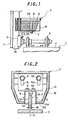
- a guide rail lubricating device 2 for an elevator 1 is arranged above a guide shoe support frame 5, which causes an ascending/descending unit 4 as a car or a balance weight to ascend or descend along a guide rail 3 disposed upright in a shaft.
- the guide shoe support frame 5 is mounted on a mount member 6 secured on a top part of the ascending/descending unit 4.
- a bracket 7 made of an angle steel is fixed by bolts 8,8A.
- a guide shoe 9 which has a turned square U shape in cross-section is fixedly press-fitted in the guide shoe support frame 5 as shown in FIG. 2.
- the mount member 6 is mounted on a crosshead (not shown) which is located on a top of the car.
- the guide shoe 9 is maintained in sliding contact with both sides walls 3A-1,3A-2 and an end wall 3A-3 of a guide portion 3A of the guide rail 3.
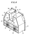
- the guide rail lubricating device 2 is provided at least with a case 12 in the form of a bottomed box, said case being made of a synthetic resin, a lid 13 made of the synthetic resin and openably closing a top opening of the case 12, and an oil-retaining member 14 removably accommodated within the case 12.
- a recess 15 through which the guide portion 3A of the guide rail 3 can extend is formed in a substantially central part of a front wall 12A of the case 12 as shown in FIG. 3 and FIG. 6.
- a recess 16 through which the guide portion 3A of the guide rail 3 can extend is formed in a substantially central part of a front wall 13A of the lid 13 as illustrated in FIG.
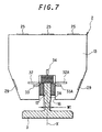
- the oil-retaining member 14 is formed primarily of a material excellent in oil absorbing property and oil retaining property, for example, kapok, and has shape retaining property. As is depicted in FIG. 3, FIG. 4 and FIG. 7, a recess 17 through which the guide portion 3A of the guide rail 3 can extend is formed at a substantially central part of a front wall 14A (FIG. 8) of the oil-retaining member 14.
- oil absorbing property as used herein means oil adsorbing ability
- the term “oil retaining property” as used herein means ability to retain a quantity of oil
- kapok as used herein means fibers contained in seeds of the DCba tree.
- pins 18,18A,18B made of the synthetic resin are integrally formed as illustrated in FIG. 5.
- the pins 18,18A,18B extend substantially upright from the inner bottom of the case 12 so that, when the lid 13 is a closed position, the pins 18,18A,18B are fitted at free ends thereof in ring-shaped sockets 19,19A,19B formed on an inner wall of the lid 13.
- the pin 18 is located adjacent a left-hand wall 15A of the recess 15 of the case 12.
- the pin 18A is located adjacent an end wall 15B (see FIG. 6) of the recess 15 of the case 12.
- the pin 18 is located adjacent a right-hand side wall 15C of the recess 15 of the case 12.
- the pin 18 and the pin 18B are arranged symmetrically on opposite sides of the recess 15 of the case 12.
- the pin 18A is located centrally rear of the end wall 15B of the recess 15 of the case 12.
- the pins 18,18A,18B are in the form of circular pins of 6 mm in diameter, but are not limited thereto. They may be in the form of square pins or oval pins.
- an inverted-setting preventing pin 20 is integrally formed to prevent the oil-retaining member 14 from being set up-side down within the case 12.
- the inverted-setting preventing pin 20 is a circular pin made of the synthetic resin and having a diameter of 6 mm, and is as long as about a half of the length of the pins 18,18A,18B.
- the inverted-setting preventing pin 20 may however be formed in the same length as the pins 18,18A,18B.
- an outer bottom of the case 12 is provided with a surrounding rib 21 formed on and along an entire outer peripheral end edge of the outer bottom, and also with a reinforcing rib 22 formed inside the surrounding rib 21.
- a horizontal flange 24 is formed on and along an entire upper end periphery of the case 12 as shown in FIG. 3 through FIG. 5.
- hinge portions 25 and two resilient rib-shaped lock elements 26 are formed on this horizontal flange 24.
- the hinge portions 25 attach the lid 13 to the case 12 such that the lid 13 can be opened and closed as desired, while the resilient rib-shaped lock elements 26 act to keep a top opening 12B of the case 12 closed when the top opening 12B is closed by the lid 13.
- Arranged on an inner wall of the lid 13 are deformation preventing ribs 27 which can be brought into contact with an inner edge of the top opening 12B of the case 12 when the top opening 12B of the case 12 is closed by the lid 13.
- An upright flange 28 is formed on an outer peripheral edge of the lid 13 except for a part corresponding to the recess 16 of the lid 13.
- the upright flange 28 is located outside the horizontal flange 24 of the case 12 when the top opening 12B of the case 12 is closed by the lid 13.
- the upright flange 28 of the lid 13 is provided with two resilient lock elements 29 formed thereon. In the state that the top opening 12B of the case 12 is closed by the lid 13, the resilient rib-shaped lock elements 26 are maintained in resilient engagement with the corresponding resilient lock elements 29 so that the closed position of the lid 13 is maintained.
- the hinge portions 25 have a plastic hinge structure.
- the case 12 is dimensioned to have a volume such that an oil-holding space H2 is formed between an upper surface of the oil-retaining member 14 and a horizontal plane, in which an upper edge of the case 12 lies, when the oil-retaining member 14 accommodated within the case 12 has been fully impregnated with lubricating oil.
- the lid 13 is provided at left-hand and right-hand side peripheral edges of the recess 16 with first insertion positioning indicators 32,32A and second insertion positioning indicators 33,33A, which serve as references for determining the inserted position of the guide portion 3A upon its insertion into the recess 17 in the oil-retaining member 14 accommodated within the case 12.
- the lid 13 is also provided on the upper surface thereof at a periphery of the end edge of the recess 16 with a center positioning indicator 34, which facilitates alignment of a center of the end edge of the recess 16 with a center position X of the guide portion 3A as viewed in the direction of a width W1.
- the center of the end edge 15B (FIG. 6) of the recess 15 of the case 12 and the center of the end edge of the recess 16 of the lid 13 are substantially registered with each other. Alignment of the center positioning indicator 34 with the center position X of the guide portion 3A as viewed in the direction of the thickness W1 therefore makes it possible to centrally arrange the guide portion 3A in the recess 15 of the case 12 and the recess 16 of the lid 13 as shown in FIG. 7.
- the case 12 and the lid 13 are designed to be usable commonly for two types of guide rails, namely, for a 13K guide rail and an 8K guide rail.
- the recess 15 of the case 12 and the recess 16 of the lid 13 are dimensioned large enough to receive therein a guide portion of a 13K guide rail without any problem. It is also necessary to provide two types of oil-retaining members 14, one for use with a 13K guide rail and the other for use with an 8K guide rail. By choosing the corresponding one of the two types of oil-retaining members 14, the case 12 and the lid 13 can be used for either the 13K guide rail or the 8K guide rail.
- the oil-retaining member 14 shown in FIG. 3, FIG. 4 and FIG. 8 is for use with a 13K guide rail.
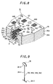
- the oil-retaining member 14 is provided with three types of oil-retaining sheets, which consist of non-contact oil-retaining sheets 35,35A,35B maintained out of contact with the guide portion 3A, first contact oil-retaining sheets 36,36A and a second contact oil-retaining sheet 37.
- the oil-retaining member 14 is fabricated by stacking the three non-contact oil-retaining sheets 35,35A,35B, the two first contact oil-retaining sheets 36,36A and the single second contact oil-retaining sheet 37 one over the other as shown in FIG. 8 and then tightening them together with four fastening members 38,38A,38B,38C. As is illustrated in FIG.
- each of the four fastening members 38,38A,38B,38C is composed of a string portion 38-1, an upper end stopper 38-2 integrally formed at an upper end of the string portion 38-1, and a rod-shaped lower end stopper 38-3 integrally formed at a lower end of the string portion 38-1.
- the upper end stopper 38-2 is also formed as a finger grip member 39 for being used to lift the oil-retaining member 39.
- the string portion 38-1, the upper end stopper 38-2, the rod-shaped lower end stopper 38-3 and the finger grip member 39 are integrally formed with a synthetic resin.
- the finger grip member 39 has been formed by making the width of the upper end stopper 38-2 greater.
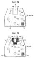
- each of the non-contact oil-retaining sheets 35,35A,35B is provided with a main body 40 made of kapok or the like, a recess 41 centrally formed in a side of the main body 40 and having a size large enough to avoid contact with the guide portion 3A, positioning through-holes 42,42A,42B permitting insertion of the pins 18,18A,18B therein, an inverted-setting preventing pin insertion bore 43 permitting insertion of the inverted-setting preventing pin 20 (FIG. 5) therein, and three oiling holes 44,44A, 44B having an opening area greater than the positioning through-holes 42,42A,42B.
- each of the first contact oil-retaining sheets 36,36A is provided with a main body 45 made of a material excellent in oil absorbing property and oil retaining property, for example, kapok, a recess 46 centrally formed in a side of the main body 45 and having a size small enough to permit contact with the guide portion 3A, positioning through-holes 47,47A,47B permitting insertion of the pins 18,18A,18B therein, an inverted-setting preventing pin insertion bore 48 permitting insertion of the inverted-setting preventing pin 20 therein, and three oiling holes 49,49A,49B having an opening area greater than the positioning through-holes 47,47A,47B.
- Side side edges 46A,46B (FIG.
- first wear-resistant meshes 50,51 which serve to prevent loosing of the associated side edges 46A,46B, respectively.
- An end edge 46C (FIG. 14) of the recess 46 in each of the first contact oil-retaining sheets 36,36A is provided with a second wear-resistant mesh 52 which serves to prevent loosing of the associated end edge 46C.
- the first wear-resistant meshes 50,51 and the second wear-resistant mesh 52 are made of nylon fibers having a 140-denier diameter and are formed in knitted structures of approximately 1 mm in thickness. As the first wear-resistant meshes 50,51 and the second wear-resistant mesh 52, those having the same dimensions and made of the same material are used.
- the first wear-resistant meshes 50,51 are sewn on the corresponding side edges 46A,46B of the recess 46 at three locations by tacks 53 made of a synthetic resin (FIG. 14).
- the second wear-resistant mesh 52 is sewn on the end edge 46C of the recess 46 at three locations by tacks 54 made of the synthetic resin (FIG. 14).
- the sewn parts of the first wear-resistant meshes 50,51 by the tacks 53 in each of the contact oil-retaining sheets 36,36A,37 are formed to extend substantially in parallel with the corresponding side edges 41A,41B of the recess 41 in the adjacent non-contact oil-retaining sheet 35 35A or 35B.
- slits 55,55A are formed extending alongside extensions of the end edge 46C.
- tongue portions 56,56A which are covered by the corresponding first wear-resistant meshes 50,51 are formed on the opposite sides of the recess 46 in each of the first contact oil-retaining sheets 36,36A.
- a gap G3 is formed between the tongue portions 56,56A and the end edge 49C so that the tongue portions 56,56A are maintained out of contact with the second wear-resistant mesh 52.
- the cut width W3 is set at approximately 2 mm.
- the tongue portions 56,56A are inwardly sunken at both sides of the base portions.
- the tongue portions 56,56A are constricted at the base portions thereof by the tacks 53.
- the tongue portions 56,56A are in such a construction that they are readily swingable about the base portions thereof.
- the size of the recess 46 in each of the first contact oil-retaining sheets 36,36A is set such that the dimension G1 (FIG. 14) of the spacing between the tongue portions 56,56A is smaller than the dimension W1 of the thickness of the guide portion 3A.
- the dimension G1 of the spacing between the tongue portions 56,56A is set at approximately 12 mm as opposed to approximately 16 mm as the dimension W1 of the thickness of the guide portion 3A.
- the guide rail lubricating device 2 is caused to ascend and descend along the guide portion 3A, the tongue portions 56,56A are maintained in sliding contact with the corresponding side walls 3A-1,3A-2 of the guide portion 3A under appropriate pushing force.
- the second wear-resistant mesh 52 arranged on the end edge 46C of the recess 46 is designed such that its free end undergoes light sliding contact with the end walls 3A-3 of the guide portion 3A.
- the pressing force of the first wear-resistant meshes 50,51 against the corresponding side walls 3A-1,3A-2 of the guide portion 3A is set greater than the pressing force of the second wear-resistant mesh 52 against the end wall 3A-3 of the guide portion 3A.
- the second contact oil-retaining sheet 37 has a structure such as that shown in FIG. 12.
- those reference signs which also appear in FIG. 11 indicate like elements.
- the first contact oil-retaining sheets 36,36A and the second contact oil-retaining sheet 37 are different only in that the former are provided with the oiling holes 49,49A,49B but the latter is not provided with the oiling holes 49,49A,49B.
- the second contact oil-retaining sheet 37 and the first contact oil-retaining sheets 36,36A will hereinafter be called “the contact oil-retaining sheets" when they will be collectively referred to.
- Each of the non-contact oil-retaining sheets 35,35A,35B is covered at the entire upper and lower sides of its main body 40 by a mesh 57.
- each of the first contact oil-retaining sheet 36,36A and the second contact oil-retaining sheet 37 is covered at the entire upper and lower sides of its main body 45 by a mesh 58.
- the meshes 57,58 have been formed by knitting nylon yarns of approximately 0.2 mm in diameter into grid patterns.
- each of the non-contact oil-retaining sheets 35,35A,35B is fabricated by putting kapok together to a thickness of approximately 6 mm to form a sheet-like preform, laying the mesh 57 over the entire upper and lower sides of the sheet-like preform, and then cutting the sheet-like preform and the mesh 57 together in a desired size.
- the oil-retaining member 14 is formed by stacking the second contact oil-retaining sheet 37, the non-contact oil-retaining sheet 35B, the first contact oil-retaining sheet 36A, the non-contact oil-retaining sheet 35A, the first contact oil-retaining sheet 36 and the non-contact oil-retaining sheet 35 one over the other in the order as they are presented.
- the oil-retaining member 14 is formed by alternately stacking the non-contact oil-retaining sheets 35,35A,35B and the contact oil-retaining sheets 36,36A,37 one over the other.
- the recess 17 of the oil-retaining member 14 is formed by the recesses 41 of the non-contact oil-retaining sheets 35,35A,35B and the recesses 46 of the first contact oil-retaining sheets 36,36A and second contact oil-retaining sheet 37.
- the tongue portions 56,56A covered by the first wear-resistant meshes 50,51 are arranged side by side and also with vertical intervals equivalent to the thickness of the non-contact oil-retaining sheets 35,35A,35B.
- the widthwise center positions of the recesses 41 of the non-contact oil-retaining sheets 35,35A,35B, the widthwise center positions of the first contact oil-retaining sheets 36,36A and the widthwise center position of the second contact oil-retaining sheet 37 are substantially registered with each other.
- the center positioning indicator 34 of the lid 13 is brought into registration with the widthwise center position of the recess 17 in the oil-retaining member 14, the first wear-resistant meshes 50,51 of the first contact oil-retaining sheets 36,36A and the first wear-resistant meshes 50,51 of he second contact oil-retaining sheet 37 are maintained in sliding contact with the side walls 3A-1,3A-2 of the guide portion 3A of the guide rail 3 symmetrically relative to the center position X of the guide portion 3A.
- the main bodies 40 of the non-contact oil-retaining sheets 35,35A,35B and the main bodies 45 of the first contact oil-retaining sheets 36,36A and the second contact oil-retaining sheet 37, except for the recesses 41 and the recesses 46, have the same contour and dimensions.
- oilways 59 are formed in the oil-retaining member 14, extending from the upper side of the non-contact oil-retaining sheet 35 to the upper side of the second oil-retaining sheet 37, because the main body 45 of the second contact oil-retaining sheet 37 does not have the oilways 49,49A,49B.
- the positioning through-holes 42,42A,42B and the positioning through-holes 47,47A,47B are dimensioned to have a diameter of approximately 6.5 mm.
- the oiling holes 44,44A,44B and the oiling holes 49,49A,49B are dimensioned to have a diameter of approximately 12 mm.
- the inverted-setting preventing pin insertion bore 43 and the inverted-setting preventing pin insertion bore 48 are dimensioned to have a diameter of approximately 6.5 mm.
- the pins 18,18A,18B are tapered at free ends thereof to facilitate their insertion into the positioning through-holes 42,42A,42B and the positioning through-holes 47,47A,47B.
- the inverted-setting preventing pin 20 is also tapered at a free end thereof to facilitate its insertion into the inverted-setting preventing pin insertion bore 43 and the inverted-setting preventing pin insertion bore 48.
- the oil-retaining member for the 8K guide rail and the oil-retaining member 14 for the 13K guide rail are substantially the same in construction, and are different only in the size of the recess through which the guide portion of the 8K guide rail extends.
- the lid 13 is then opened, and the pins 18,18A,18B and the inverted-setting preventing pin 20 are next inserted into the positioning through-holes 42,42A,42B,47,47A,47B of the oil-retaining member 14 and the inverted-setting preventing pin insertion bores 43,48 of the oil-retaining member 14, respectively.
- the oil-retaining member 14 is arranged with the case 12 as shown in FIG. 4.
- the inverted-setting preventing pin insertion bores 43,48 become offset from the position where the inverted-setting preventing pin 20 is located.
- the inverted-setting preventing pin 20 cannot therefore be inserted into the inverted-setting preventing pin insertion bores 43,48, so that the oil-retaining member 14 cannot be arranged within the case 12.
- the oil-retaining member 14 the non-contact oil-retaining sheets 35,35A,35B, the first contact oil-retaining sheets 36,36A and the second contact oil-retaining sheet 37 are used in the form of a fastened unit instead of arranging the non-contact oil-retaining sheets 35,35A,35B, the first contact oil-retaining sheets 36,36A and the second contact oil-retaining sheet 37 one after one in the case 12.
- the arrangement work of the retaining member 14 in the case 14 can therefore be performed easily in a short time.
- a predetermined quantity of lubricating oil is then poured by an oil feeding funnel (oiler) into the oiling holes 44,44A,44B of the non-contact oil-retaining sheet 35 in the oil-retaining member 14.
- the lubricating oil which has been poured into the oiling holes 44,44A,44B, is instantaneously allowed to flow through the oilways 59 to the upper side of the second contact oil-retaining sheet 37 located in the bottom part of the case 12 so that the second contact oil-retaining sheet 37 is soaked with the lubricating oil.
- the lubricating oil is also allowed to smoothly penetrate from the oilways 59 via the meshes 57,58 to both the upper and lower sides of the first contact oil-retaining sheets 36,37A and non-contact oil-retaining sheet 35A,35B, which are located between the non-contact oil-retaining sheet 35 and the second contact oil-retaining sheet 37, and also to the entire lower side of the non-contact oil-retaining sheet 35 and the entire upper side of the second contact oil-retaining sheet 37.
- the oiling time of the lubricating oil can therefore be shortened.
- the second contact oil-retaining sheet 37 is free of the oiling holes 44,44A,44B, so that this embodiment is free of such a problem that the lubricating oil may instantaneously flow to the inner bottom of the case 12 through the oilways 59 and may hence overflow from the case 12.
- each tongue portion 56 covered by the corresponding first wear-resistant mesh 50 is upwardly swung about the base portion thereof and is hence brought into sliding contact with the side wall 3A-1 of the guide portion 3A, as is illustrated in FIG. 15.
- each tongue portion 56A covered by its corresponding first wear-resistant mesh 51 is also upwardly swung about the base portion thereof and is hence brought into sliding contact with the side wall 3A-2 of the guide portion 3A.
- each tongue portion 56 covered by the corresponding first wear-resistant mesh 50 is downwardly swung about the base portion thereof and is hence brought into sliding contact with the side wall 3A-1 of the guide portion 3A, as is illustrated in FIG. 16.
- each tongue portion 56A covered by its corresponding first wear-resistant mesh 51 is also downwardly swung about the base portion thereof and is hence brought into sliding contact with the side wall 3A-2 of the guide portion 3A.
- the second wear-resistant mesh 52 is designed to remain out of contact with the tongue portions 56,56A covered by the first wear-resistant meshes 50,51 owing to the formation of the gap G3 by the arrangement of the slits 55,55A, which have the cut width W3 greater than the thickness of the second wear-resistant mesh 52, between the side edges 46A,46B and the end edge 46C of the recess 46 in the corresponding one of the first contact oil-retaining sheets 36,36A and second contact oil-retaining sheet 37 as illustrated in FIG. 14.
- the tongue portions 56,56A are therefore resistant to outward flaring which would otherwise occur as a result of outward pushing of the second wear-resistant mesh 52 by the tongue portions 56,56A.
- the whole tongue portions 56,56A are allowed to undergo uniform sliding contact with the side walls 3A-1,3A-2 of the guide portion 3A.
- any extra lubricating oil can be absorbed back toward the tongue portions 56,56A by the kapok forming the tongue portions 56,56A because the whole tongue portions 56,56A are maintained in uniform sliding contact with the side walls 3A-1,3A-2 of the guide portion 3A. Lubricating oil therefore does not flow down into a pit of the elevator 1 along the guide rail 3.
- the tongue portions 56,56A are maintained in sliding contact with the side walls 3A-1,3A-2 of the guide portion 3A, the tongue portions 56,56A are not positionally displaced in horizontal direction owing to the fitted insertion of the pins 18,18A,18B in the positioning through-holes 42,42A,42A, 47,47A,47B of the oil-retaining member 14.
- the tongue portions 56,56A therefore do not develop a one-side contacting phenomenon such that the tongue portion 56 becomes apart from the side wall 3A-1 of the guide portion 3A and the tongue portion 56A is strongly pressed against the side wall 3A-2 of the guide portion 3A or the tongue portion 56A becomes apart from the side wall 3A-2 of the guide portion 3A and the tongue portion 56 is strongly pressed against the side wall 3A-1 of the guide portion 3A.
- Lubricating oil is therefore surely coated on the side walls 3A-1,3A-2 of the guide portion 3A and the tongue portions 56,56A are prevented from being pressed under abnormally strong force against the side walls 3A-1,3A-2 of the guide portion 3A.
- the first wear-resistant meshes 50,51 are therefore protected from abnormal wearing.
- the sewn parts of the first wear-resistant meshes 50,51 by the tacks 53 extend substantially in parallel with the side edges 41A,41B of the recesses 41 in the non-contact oil-retaining sheets 35,35A,35B, the sewn parts act as the base portions of the tongue portions 56,56A when the tongue portions 56,56A are brought into sliding contact with the side walls 3A-1, 3A-2 of the guide portion 3A by causing the ascending/descending unit 4 to ascend or descend.
- the tongue portions 56,56A are therefore allowed to smoothly swing about the base portions.
- the base portions of the tongue portions 56,56A are inwardly sunken on both sides thereof by the tacks 53.
- the first anti-wear meshes 50,51 - which are arranged on the side edges 46A,46B of the recesses 46 in the first contact oil-retaining sheets 36,36A and second contact oil-retaining sheet 37 - and the second anti-wear meshes 52 - which are arranged on the end edges of the recesses 46 in the first contact oil-retaining sheets 36,36A and second contact oil-retaining sheet 37 - are made of nylon fibers having a 140-denier diameter and are formed in knitted structures of approximately 1 mm in thickness, so that loosing will be observed neither on the first anti-wear meshes 50,51 maintained in sliding contact with the side walls 3A-1,3A-2 of the guide portion 3A nor on the second anti-wear meshes 52 maintained in sliding contact with the end wall 3A-3 of the guide portion 3A.
- the second anti-wear meshes 52 arranged on the end edges 46C of the recesses 46 in the first contact oil-retaining sheets 36,36A and second contact oil-retaining sheet 37 are arranged such that they are maintained in light sliding contact at the free edges thereof with the end wall 3A-3 of the guide portion 3A. The end edges 46 are therefore protected from being caused to swing under strong force.
- the pressing force of the first anti-wear meshes 50,51 against the side walls 3A-1,3A-2 of the guide portion 3A becomes greater than the pressing force of the second anti-wear meshes 52 against the end wall 3A-3 of the guide portion 3A.
- the tongue portions 56,56A located at the top in the recess 17 of the oil-retaining member 14 are not strongly squeezed between the edge of the recess 16 in the lid 13 and the corresponding side walls 3A-1,3A-2 of the guide portion 3A although the tongue portions 56,56A are caused to swing upwardly.
- the tongue portions 56,56A located at the bottom in the recess 17 of the oil-retaining member 14 are not strongly squeezed between the edge of the recess 15 in the case 12 and the corresponding side walls 3A-1,3A-2 of the guide portion 3A although the tongue portions 56,56A are caused to swing downwardly. Lubricating oil therefore does not flow out excessively from the tongue portions 56,56A.
- first anti-wear meshes 50,51 and the second anti-wear meshes 52 are made of the same material and have the same dimensions, it is possible to sew the second anti-wear mesh 52 on the side edges 46A,46B of the recess 46 in each of the contact oil-retaining sheets 36,36A,37 or to sew the first anti-wear meshes 50,51 on the end edge 46C of the recess 46 in each of the contact oil-retaining sheets 36,36A,37. This makes it possible to avoid errors upon fabrication of the oil-retaining member 14. Moreover, only one type of parts are needed as the first anti-wear meshes 50,51 and the second anti-wear meshes 52. This facilitates management of parts at a fabrication site and brings about excellent productivity.
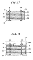
- the oil-retaining member 14 In a state that the oil-retaining member 14 has not been impregnated with lubricating oil, the oil-retaining member 14 is fully expanded between the upper end stoppers 38-2 and the rod-shaped lower end stoppers of the fastening members 38,38A,38B,38C as illustrated in FIG. 17. In a state that the oil-retaining member 14 has been fully impregnated with lubricating oil, on the other hand, the oil-retaining member 14 is shrunk in the stacked direction so that the spacing G2 is formed between the finger grip members 39 and the upper surface of the oil-retaining member 14, as is illustrated in FIG. 18. This makes it possible to minimize the inconvenience that upon pulling the oil-retaining member 14 out of the case 12, the hand of a worker may be fouled with lubricating oil even when the oil-retaining member 14 is lifted upwards at the finger grip member 39.
- the recess 15 in the case 12 is prone to deformation when external force is applied to the case.
- the deformation preventing ribs 27 are brought into contact with the inner edge of the top opening 12B of the case 12 to prevent deformation of the recess 15 in the case 12.
- the lid 13 is made of synthetic resin, it is not readily deformed owing to the upright flange 28 and the deformation preventing ribs 27 on the outer peripheral end of the lid 13.
- the case 12 and the lid 13 can be commonly used for two types of guide rails, a 13K guide rails and an 8K guide rail provided that the oil-retaining member 14 for the 13K guide rail is replaced by an oil-retaining member for the 8K guide rail.
- the oil-retaining member 14 is formed in a construction that a wiping sheet 60 may be detachably arranged on at least one of the upper and lower surfaces of the oil-retaining member 14 such that the wiping sheet 60 can be maintained in contact with the guide portion 3A to clean the side edges 3A-1,3A-2 and end edge 3A-3 of the guide portion 3A.
- FIG. 19 illustrates the external profile of the wiping sheet 60.
- FIG. 20 shows the oil-retaining member 14 with the wiping sheet 60 attached to the upper surface of the oil-retaining member 14. At the site of a newly arranged elevator, the oil-retaining member 14 with the wiping sheet 60 attached as shown in FIG.
- the wiping sheet 60 is then detached from the oil-retaining member 14, and the oil-retaining member 14 is brought into sliding contact only at the tongue portions 56,56A and second anti-wear meshes 52 thereof with the side walls 3A-1,3A-2 and end wall 3A-3 of the guide portion 3A.
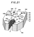
- the oil-retaining member 1 was formed by alternately stacking the non-contact oil-retaining sheets 35,35A,35B and the contact oil-retaining sheets 36,36A,37 one over the other. Where an overflow of lubricating oil toward the side walls 3A-1,3A-2 and end wall 3A-3 of the guide portion 3A is permitted, six contact oil-retaining sheets alone may be stacked one over the other as in the case of an oil-retaining member 140 shown in FIG. 21. In FIG. 21, those reference signs which also appear in FIG. 8 indicate like elements.
Landscapes
- Lift-Guide Devices, And Elevator Ropes And Cables (AREA)
- General Details Of Gearings (AREA)
Applications Claiming Priority (6)
| Application Number | Priority Date | Filing Date | Title |
|---|---|---|---|
| JP17887898A JP3231279B2 (ja) | 1998-06-25 | 1998-06-25 | ガイドレール給油装置 |
| JP17887898 | 1998-06-25 | ||
| JP19195998A JP3336258B2 (ja) | 1998-07-07 | 1998-07-07 | ガイドレール給油装置 |
| JP19195998 | 1998-07-07 | ||
| JP5156399 | 1999-02-26 | ||
| JP05156399A JP3361469B2 (ja) | 1999-02-26 | 1999-02-26 | エレベーターのガイドレール用潤滑装置並びにその潤滑装置用収納ケース及び保油部材 |
Publications (3)
| Publication Number | Publication Date |
|---|---|
| EP0967171A2 true EP0967171A2 (de) | 1999-12-29 |
| EP0967171A3 EP0967171A3 (de) | 2000-12-20 |
| EP0967171B1 EP0967171B1 (de) | 2004-10-06 |
Family
ID=27294363
Family Applications (1)
| Application Number | Title | Priority Date | Filing Date |
|---|---|---|---|
| EP99200822A Expired - Lifetime EP0967171B1 (de) | 1998-06-25 | 1999-03-16 | Laufschiene-Schmiereinrichtung für Aufzug |
Country Status (4)
| Country | Link |
|---|---|
| US (1) | US6098756A (de) |
| EP (1) | EP0967171B1 (de) |
| KR (1) | KR100432869B1 (de) |
| DE (1) | DE69920811T2 (de) |
Cited By (5)
| Publication number | Priority date | Publication date | Assignee | Title |
|---|---|---|---|---|
| EP1591401A4 (de) * | 2002-12-09 | 2010-09-08 | Toshiba Elevator Kk | Aufzugskabine |
| CN102372214A (zh) * | 2010-08-04 | 2012-03-14 | 株式会社日立建筑系统 | 电梯的导轨供油装置 |
| CN104787644A (zh) * | 2015-05-08 | 2015-07-22 | 吴江骏达电梯部件有限公司 | 一种新型电梯专用油杯 |
| CN108349698A (zh) * | 2015-10-27 | 2018-07-31 | 通力股份公司 | 维护装置和方法 |
| WO2026068453A1 (en) * | 2024-09-27 | 2026-04-02 | Inventio Ag | A lubricator for an elevator installation |
Families Citing this family (9)
| Publication number | Priority date | Publication date | Assignee | Title |
|---|---|---|---|---|
| JP3308944B2 (ja) | 1998-12-04 | 2002-07-29 | テイエチケー株式会社 | 案内装置の防塵構造 |
| US20020124706A1 (en) * | 2000-12-05 | 2002-09-12 | Isel Co., Ltd. | Guide device for linear motion |
| JP4614836B2 (ja) * | 2005-07-05 | 2011-01-19 | 株式会社日立ビルシステム | エレベータのガイドレール用潤滑装置 |
| US7775324B2 (en) * | 2006-03-23 | 2010-08-17 | Thomas Peter Corden | Treadmill lubrication device |
| CN102652104B (zh) * | 2009-12-18 | 2014-06-11 | 奥的斯电梯公司 | 运动学地驱动的缓慢传送润滑系统 |
| EP2957533A1 (de) * | 2014-06-18 | 2015-12-23 | Kone Corporation | Ölsammelvorrichtung für Führungsschienen |
| JP6360122B2 (ja) * | 2016-10-19 | 2018-07-18 | ファナック株式会社 | 排液機構、及び排液機構を備えた工作機械 |
| CN107477346B (zh) * | 2017-09-30 | 2020-11-03 | 京东方科技集团股份有限公司 | 导轨注油工具 |
| CN108910664A (zh) * | 2018-09-14 | 2018-11-30 | 南通四建集团有限公司 | 一种建筑施工用升降机的降噪结构 |
Family Cites Families (15)
| Publication number | Priority date | Publication date | Assignee | Title |
|---|---|---|---|---|
| DD53866A (de) * | ||||
| US787978A (en) * | 1905-01-19 | 1905-04-25 | Charles Hubert Eggler | Lubricator for elevator-guides. |
| US1045977A (en) * | 1910-05-20 | 1912-12-03 | Joseph H Hirz | Traveling lubricator for guide-bars. |
| US1007422A (en) * | 1911-02-16 | 1911-10-31 | Otto Berger | Lubricator for elevator-guides. |
| US1102641A (en) * | 1913-03-21 | 1914-07-07 | Otto Berger | Lubricator for elevator-guides. |
| US1109125A (en) * | 1913-06-19 | 1914-09-01 | Martin M Heisler | Lubricator. |
| US1274942A (en) * | 1913-08-26 | 1918-08-06 | Elevator Supplies Co Inc | Lubricator for elevator-guides and the like. |
| US1290618A (en) * | 1917-08-06 | 1919-01-07 | Franklin Brass Mfg Company | Oiler. |
| US1643038A (en) * | 1923-08-15 | 1927-09-20 | Raymond Winship Bristol Doing | Guide-rail lubricator |
| GB303299A (en) * | 1928-03-05 | 1929-01-03 | Gustav Mauritz Osterberg | Rail oiler |
| US1805305A (en) * | 1929-09-19 | 1931-05-12 | Otis Elevator Co | Lubricating device for elevator guide rails |
| US1944666A (en) * | 1930-11-06 | 1934-01-23 | Gustav M Osterberg | Rail oiler |
| US1897764A (en) * | 1931-03-31 | 1933-02-14 | Otis Elevator Co | Guide rail lubricator |
| JPS6487229A (en) * | 1987-09-29 | 1989-03-31 | Daiso Co Ltd | Heat-shrinkable molded material |
| ATE132956T1 (de) * | 1992-11-27 | 1996-01-15 | Satzinger Gmbh & Co | Vorrichtung zum schmieren und reinigen insbesondere von ketten und schienen |
-
1999
- 1999-03-16 DE DE69920811T patent/DE69920811T2/de not_active Expired - Lifetime
- 1999-03-16 KR KR10-1999-0008748A patent/KR100432869B1/ko not_active Expired - Lifetime
- 1999-03-16 US US09/270,015 patent/US6098756A/en not_active Expired - Lifetime
- 1999-03-16 EP EP99200822A patent/EP0967171B1/de not_active Expired - Lifetime
Cited By (6)
| Publication number | Priority date | Publication date | Assignee | Title |
|---|---|---|---|---|
| EP1591401A4 (de) * | 2002-12-09 | 2010-09-08 | Toshiba Elevator Kk | Aufzugskabine |
| CN102372214A (zh) * | 2010-08-04 | 2012-03-14 | 株式会社日立建筑系统 | 电梯的导轨供油装置 |
| CN102372214B (zh) * | 2010-08-04 | 2014-06-11 | 株式会社日立建筑系统 | 电梯的导轨供油装置 |
| CN104787644A (zh) * | 2015-05-08 | 2015-07-22 | 吴江骏达电梯部件有限公司 | 一种新型电梯专用油杯 |
| CN108349698A (zh) * | 2015-10-27 | 2018-07-31 | 通力股份公司 | 维护装置和方法 |
| WO2026068453A1 (en) * | 2024-09-27 | 2026-04-02 | Inventio Ag | A lubricator for an elevator installation |
Also Published As
| Publication number | Publication date |
|---|---|
| EP0967171B1 (de) | 2004-10-06 |
| KR20000005614A (ko) | 2000-01-25 |
| DE69920811D1 (de) | 2004-11-11 |
| DE69920811T2 (de) | 2005-11-24 |
| KR100432869B1 (ko) | 2004-05-22 |
| EP0967171A3 (de) | 2000-12-20 |
| US6098756A (en) | 2000-08-08 |
Similar Documents
| Publication | Publication Date | Title |
|---|---|---|
| EP0967171B1 (de) | Laufschiene-Schmiereinrichtung für Aufzug | |
| US5251780A (en) | Refuse container having removable wear-resistant pads | |
| US7784763B2 (en) | Transmission mount | |
| CZ303122B6 (cs) | Nerozpojitelné spojovací zarízení pro spojení dvou koncu dopravníkového pásu a zpusob jeho výroby | |
| US4667625A (en) | Dog run apparatus having shock absorbing capability | |
| JP3361469B2 (ja) | エレベーターのガイドレール用潤滑装置並びにその潤滑装置用収納ケース及び保油部材 | |
| JPS61180009A (ja) | 保持リング | |
| US20020094917A1 (en) | Punching bag assembly | |
| JP3167627B2 (ja) | エレベータのガイドレール潤滑装置 | |
| JP2001171944A (ja) | エレベータのガイドレール用潤滑装置 | |
| US20070034451A1 (en) | Pneumatic grease applicator | |
| US4827707A (en) | Zinc alloy body for braiding machine carrier | |
| US20230390805A1 (en) | Improvements in screening panels | |
| KR102344442B1 (ko) | 골재 선별용 러버 스크린의 구조 | |
| US4357791A (en) | Noise and vibration dampening ring mount | |
| KR20230011649A (ko) | 유지보수가 용이한 컨베이어시스템 | |
| JP3377544B2 (ja) | 乗客コンベアのフレームの据付方法 | |
| JP2022099775A (ja) | 金車 | |
| JPH0352775Y2 (de) | ||
| KR102532098B1 (ko) | 컨베이어 벨트의 작동여부 알림수단을 구비한 컨베이어 시스템 | |
| JPS6111182Y2 (de) | ||
| KR100706025B1 (ko) | 용접 와이어용 페일팩 용기 | |
| JPH081245U (ja) | 精紡機用セパレーター | |
| JPS6321578Y2 (de) | ||
| CA2134401C (en) | Air passage insert for oil fill spout |
Legal Events
| Date | Code | Title | Description |
|---|---|---|---|
| PUAI | Public reference made under article 153(3) epc to a published international application that has entered the european phase |
Free format text: ORIGINAL CODE: 0009012 |
|
| AK | Designated contracting states |
Kind code of ref document: A2 Designated state(s): CH DE FI LI |
|
| AX | Request for extension of the european patent |
Free format text: AL;LT;LV;MK;RO;SI |
|
| PUAL | Search report despatched |
Free format text: ORIGINAL CODE: 0009013 |
|
| AK | Designated contracting states |
Kind code of ref document: A3 Designated state(s): AT BE CH CY DE DK ES FI FR GB GR IE IT LI LU MC NL PT SE |
|
| AX | Request for extension of the european patent |
Free format text: AL;LT;LV;MK;RO;SI |
|
| 17P | Request for examination filed |
Effective date: 20010515 |
|
| AKX | Designation fees paid |
Free format text: CH DE FI LI |
|
| 17Q | First examination report despatched |
Effective date: 20030320 |
|
| GRAP | Despatch of communication of intention to grant a patent |
Free format text: ORIGINAL CODE: EPIDOSNIGR1 |
|
| GRAS | Grant fee paid |
Free format text: ORIGINAL CODE: EPIDOSNIGR3 |
|
| GRAA | (expected) grant |
Free format text: ORIGINAL CODE: 0009210 |
|
| AK | Designated contracting states |
Kind code of ref document: B1 Designated state(s): CH DE FI LI |
|
| REG | Reference to a national code |
Ref country code: CH Ref legal event code: EP |
|
| REF | Corresponds to: |
Ref document number: 69920811 Country of ref document: DE Date of ref document: 20041111 Kind code of ref document: P |
|
| REG | Reference to a national code |
Ref country code: CH Ref legal event code: NV Representative=s name: ISLER & PEDRAZZINI AG |
|
| PLBE | No opposition filed within time limit |
Free format text: ORIGINAL CODE: 0009261 |
|
| STAA | Information on the status of an ep patent application or granted ep patent |
Free format text: STATUS: NO OPPOSITION FILED WITHIN TIME LIMIT |
|
| 26N | No opposition filed |
Effective date: 20050707 |
|
| REG | Reference to a national code |
Ref country code: CH Ref legal event code: PCAR Free format text: ISLER & PEDRAZZINI AG;POSTFACH 1772;8027 ZUERICH (CH) |
|
| PGFP | Annual fee paid to national office [announced via postgrant information from national office to epo] |
Ref country code: FI Payment date: 20180312 Year of fee payment: 20 Ref country code: CH Payment date: 20180314 Year of fee payment: 20 Ref country code: DE Payment date: 20180306 Year of fee payment: 20 |
|
| REG | Reference to a national code |
Ref country code: DE Ref legal event code: R071 Ref document number: 69920811 Country of ref document: DE |
|
| REG | Reference to a national code |
Ref country code: CH Ref legal event code: PL |