EP0967174B1 - Dispositif de reformage - Google Patents
Dispositif de reformage Download PDFInfo
- Publication number
- EP0967174B1 EP0967174B1 EP99305137A EP99305137A EP0967174B1 EP 0967174 B1 EP0967174 B1 EP 0967174B1 EP 99305137 A EP99305137 A EP 99305137A EP 99305137 A EP99305137 A EP 99305137A EP 0967174 B1 EP0967174 B1 EP 0967174B1
- Authority
- EP
- European Patent Office
- Prior art keywords
- catalyst
- unit
- heater unit
- cell density
- upstream
- Prior art date
- Legal status (The legal status is an assumption and is not a legal conclusion. Google has not performed a legal analysis and makes no representation as to the accuracy of the status listed.)
- Expired - Lifetime
Links
Images


Classifications
-
- H—ELECTRICITY
- H01—ELECTRIC ELEMENTS
- H01M—PROCESSES OR MEANS, e.g. BATTERIES, FOR THE DIRECT CONVERSION OF CHEMICAL ENERGY INTO ELECTRICAL ENERGY
- H01M8/00—Fuel cells; Manufacture thereof
- H01M8/06—Combination of fuel cells with means for production of reactants or for treatment of residues
- H01M8/0606—Combination of fuel cells with means for production of reactants or for treatment of residues with means for production of gaseous reactants
- H01M8/0612—Combination of fuel cells with means for production of reactants or for treatment of residues with means for production of gaseous reactants from carbon-containing material
- H01M8/0625—Combination of fuel cells with means for production of reactants or for treatment of residues with means for production of gaseous reactants from carbon-containing material in a modular combined reactor/fuel cell structure
- H01M8/0631—Reactor construction specially adapted for combination reactor/fuel cell
-
- B—PERFORMING OPERATIONS; TRANSPORTING
- B01—PHYSICAL OR CHEMICAL PROCESSES OR APPARATUS IN GENERAL
- B01J—CHEMICAL OR PHYSICAL PROCESSES, e.g. CATALYSIS OR COLLOID CHEMISTRY; THEIR RELEVANT APPARATUS
- B01J15/00—Chemical processes in general for reacting gaseous media with non-particulate solids, e.g. sheet material; Apparatus specially adapted therefor
- B01J15/005—Chemical processes in general for reacting gaseous media with non-particulate solids, e.g. sheet material; Apparatus specially adapted therefor in the presence of catalytically active bodies, e.g. porous plates
-
- B—PERFORMING OPERATIONS; TRANSPORTING
- B01—PHYSICAL OR CHEMICAL PROCESSES OR APPARATUS IN GENERAL
- B01J—CHEMICAL OR PHYSICAL PROCESSES, e.g. CATALYSIS OR COLLOID CHEMISTRY; THEIR RELEVANT APPARATUS
- B01J19/00—Chemical, physical or physico-chemical processes in general; Their relevant apparatus
- B01J19/24—Stationary reactors without moving elements inside
- B01J19/248—Reactors comprising multiple separated flow channels
- B01J19/2485—Monolithic reactors
-
- C—CHEMISTRY; METALLURGY
- C01—INORGANIC CHEMISTRY
- C01B—NON-METALLIC ELEMENTS; COMPOUNDS THEREOF; METALLOIDS OR COMPOUNDS THEREOF NOT COVERED BY SUBCLASS C01C
- C01B3/00—Hydrogen; Gaseous mixtures containing hydrogen; Separation of hydrogen from mixtures containing it; Purification of hydrogen; Reversible storage of hydrogen
- C01B3/02—Production of hydrogen; Production of gaseous mixtures containing hydrogen
- C01B3/06—Production of hydrogen; Production of gaseous mixtures containing hydrogen by reaction of inorganic compounds containing electro-positively bound hydrogen with inorganic reducing agents
- C01B3/12—Production of hydrogen; Production of gaseous mixtures containing hydrogen by reaction of inorganic compounds containing electro-positively bound hydrogen with inorganic reducing agents by reaction of water vapour with carbon monoxide
- C01B3/16—Production of hydrogen; Production of gaseous mixtures containing hydrogen by reaction of inorganic compounds containing electro-positively bound hydrogen with inorganic reducing agents by reaction of water vapour with carbon monoxide using catalysts
-
- C—CHEMISTRY; METALLURGY
- C01—INORGANIC CHEMISTRY
- C01B—NON-METALLIC ELEMENTS; COMPOUNDS THEREOF; METALLOIDS OR COMPOUNDS THEREOF NOT COVERED BY SUBCLASS C01C
- C01B3/00—Hydrogen; Gaseous mixtures containing hydrogen; Separation of hydrogen from mixtures containing it; Purification of hydrogen; Reversible storage of hydrogen
- C01B3/02—Production of hydrogen; Production of gaseous mixtures containing hydrogen
- C01B3/22—Production of hydrogen; Production of gaseous mixtures containing hydrogen by decomposition of gaseous or liquid organic compounds
- C01B3/24—Production of hydrogen; Production of gaseous mixtures containing hydrogen by decomposition of gaseous or liquid organic compounds of hydrocarbons
- C01B3/26—Production of hydrogen; Production of gaseous mixtures containing hydrogen by decomposition of gaseous or liquid organic compounds of hydrocarbons using catalysts
-
- C—CHEMISTRY; METALLURGY
- C01—INORGANIC CHEMISTRY
- C01B—NON-METALLIC ELEMENTS; COMPOUNDS THEREOF; METALLOIDS OR COMPOUNDS THEREOF NOT COVERED BY SUBCLASS C01C
- C01B3/00—Hydrogen; Gaseous mixtures containing hydrogen; Separation of hydrogen from mixtures containing it; Purification of hydrogen; Reversible storage of hydrogen
- C01B3/02—Production of hydrogen; Production of gaseous mixtures containing hydrogen
- C01B3/32—Production of hydrogen; Production of gaseous mixtures containing hydrogen by reaction of gaseous or liquid organic compounds with gasifying agents, e.g. water, carbon dioxide or air
- C01B3/323—Catalytic reaction of gaseous or liquid organic compounds other than hydrocarbons with gasifying agents
-
- C—CHEMISTRY; METALLURGY
- C01—INORGANIC CHEMISTRY
- C01B—NON-METALLIC ELEMENTS; COMPOUNDS THEREOF; METALLOIDS OR COMPOUNDS THEREOF NOT COVERED BY SUBCLASS C01C
- C01B3/00—Hydrogen; Gaseous mixtures containing hydrogen; Separation of hydrogen from mixtures containing it; Purification of hydrogen; Reversible storage of hydrogen
- C01B3/02—Production of hydrogen; Production of gaseous mixtures containing hydrogen
- C01B3/32—Production of hydrogen; Production of gaseous mixtures containing hydrogen by reaction of gaseous or liquid organic compounds with gasifying agents, e.g. water, carbon dioxide or air
- C01B3/34—Production of hydrogen; Production of gaseous mixtures containing hydrogen by reaction of gaseous or liquid organic compounds with gasifying agents, e.g. water, carbon dioxide or air by reaction of hydrocarbons with gasifying agents
- C01B3/38—Production of hydrogen; Production of gaseous mixtures containing hydrogen by reaction of gaseous or liquid organic compounds with gasifying agents, e.g. water, carbon dioxide or air by reaction of hydrocarbons with gasifying agents using catalysts
-
- B—PERFORMING OPERATIONS; TRANSPORTING
- B01—PHYSICAL OR CHEMICAL PROCESSES OR APPARATUS IN GENERAL
- B01J—CHEMICAL OR PHYSICAL PROCESSES, e.g. CATALYSIS OR COLLOID CHEMISTRY; THEIR RELEVANT APPARATUS
- B01J2219/00—Chemical, physical or physico-chemical processes in general; Their relevant apparatus
- B01J2219/00049—Controlling or regulating processes
- B01J2219/00051—Controlling the temperature
- B01J2219/00132—Controlling the temperature using electric heating or cooling elements
- B01J2219/00135—Electric resistance heaters
-
- B—PERFORMING OPERATIONS; TRANSPORTING
- B01—PHYSICAL OR CHEMICAL PROCESSES OR APPARATUS IN GENERAL
- B01J—CHEMICAL OR PHYSICAL PROCESSES, e.g. CATALYSIS OR COLLOID CHEMISTRY; THEIR RELEVANT APPARATUS
- B01J2219/00—Chemical, physical or physico-chemical processes in general; Their relevant apparatus
- B01J2219/18—Details relating to the spatial orientation of the reactor
- B01J2219/182—Details relating to the spatial orientation of the reactor horizontal
-
- C—CHEMISTRY; METALLURGY
- C01—INORGANIC CHEMISTRY
- C01B—NON-METALLIC ELEMENTS; COMPOUNDS THEREOF; METALLOIDS OR COMPOUNDS THEREOF NOT COVERED BY SUBCLASS C01C
- C01B2203/00—Integrated processes for the production of hydrogen or synthesis gas
- C01B2203/02—Processes for making hydrogen or synthesis gas
- C01B2203/0205—Processes for making hydrogen or synthesis gas containing a reforming step
- C01B2203/0227—Processes for making hydrogen or synthesis gas containing a reforming step containing a catalytic reforming step
- C01B2203/0233—Processes for making hydrogen or synthesis gas containing a reforming step containing a catalytic reforming step the reforming step being a steam reforming step
-
- C—CHEMISTRY; METALLURGY
- C01—INORGANIC CHEMISTRY
- C01B—NON-METALLIC ELEMENTS; COMPOUNDS THEREOF; METALLOIDS OR COMPOUNDS THEREOF NOT COVERED BY SUBCLASS C01C
- C01B2203/00—Integrated processes for the production of hydrogen or synthesis gas
- C01B2203/02—Processes for making hydrogen or synthesis gas
- C01B2203/025—Processes for making hydrogen or synthesis gas containing a partial oxidation step
- C01B2203/0261—Processes for making hydrogen or synthesis gas containing a partial oxidation step containing a catalytic partial oxidation step [CPO]
-
- C—CHEMISTRY; METALLURGY
- C01—INORGANIC CHEMISTRY
- C01B—NON-METALLIC ELEMENTS; COMPOUNDS THEREOF; METALLOIDS OR COMPOUNDS THEREOF NOT COVERED BY SUBCLASS C01C
- C01B2203/00—Integrated processes for the production of hydrogen or synthesis gas
- C01B2203/02—Processes for making hydrogen or synthesis gas
- C01B2203/0266—Processes for making hydrogen or synthesis gas containing a decomposition step
- C01B2203/0277—Processes for making hydrogen or synthesis gas containing a decomposition step containing a catalytic decomposition step
-
- C—CHEMISTRY; METALLURGY
- C01—INORGANIC CHEMISTRY
- C01B—NON-METALLIC ELEMENTS; COMPOUNDS THEREOF; METALLOIDS OR COMPOUNDS THEREOF NOT COVERED BY SUBCLASS C01C
- C01B2203/00—Integrated processes for the production of hydrogen or synthesis gas
- C01B2203/02—Processes for making hydrogen or synthesis gas
- C01B2203/0283—Processes for making hydrogen or synthesis gas containing a CO-shift step, i.e. a water gas shift step
- C01B2203/0288—Processes for making hydrogen or synthesis gas containing a CO-shift step, i.e. a water gas shift step containing two CO-shift steps
-
- C—CHEMISTRY; METALLURGY
- C01—INORGANIC CHEMISTRY
- C01B—NON-METALLIC ELEMENTS; COMPOUNDS THEREOF; METALLOIDS OR COMPOUNDS THEREOF NOT COVERED BY SUBCLASS C01C
- C01B2203/00—Integrated processes for the production of hydrogen or synthesis gas
- C01B2203/04—Integrated processes for the production of hydrogen or synthesis gas containing a purification step for the hydrogen or the synthesis gas
- C01B2203/0435—Catalytic purification
- C01B2203/044—Selective oxidation of carbon monoxide
-
- C—CHEMISTRY; METALLURGY
- C01—INORGANIC CHEMISTRY
- C01B—NON-METALLIC ELEMENTS; COMPOUNDS THEREOF; METALLOIDS OR COMPOUNDS THEREOF NOT COVERED BY SUBCLASS C01C
- C01B2203/00—Integrated processes for the production of hydrogen or synthesis gas
- C01B2203/04—Integrated processes for the production of hydrogen or synthesis gas containing a purification step for the hydrogen or the synthesis gas
- C01B2203/0465—Composition of the impurity
- C01B2203/047—Composition of the impurity the impurity being carbon monoxide
-
- C—CHEMISTRY; METALLURGY
- C01—INORGANIC CHEMISTRY
- C01B—NON-METALLIC ELEMENTS; COMPOUNDS THEREOF; METALLOIDS OR COMPOUNDS THEREOF NOT COVERED BY SUBCLASS C01C
- C01B2203/00—Integrated processes for the production of hydrogen or synthesis gas
- C01B2203/06—Integration with other chemical processes
- C01B2203/066—Integration with other chemical processes with fuel cells
-
- C—CHEMISTRY; METALLURGY
- C01—INORGANIC CHEMISTRY
- C01B—NON-METALLIC ELEMENTS; COMPOUNDS THEREOF; METALLOIDS OR COMPOUNDS THEREOF NOT COVERED BY SUBCLASS C01C
- C01B2203/00—Integrated processes for the production of hydrogen or synthesis gas
- C01B2203/08—Methods of heating or cooling
- C01B2203/0805—Methods of heating the process for making hydrogen or synthesis gas
- C01B2203/085—Methods of heating the process for making hydrogen or synthesis gas by electric heating
-
- C—CHEMISTRY; METALLURGY
- C01—INORGANIC CHEMISTRY
- C01B—NON-METALLIC ELEMENTS; COMPOUNDS THEREOF; METALLOIDS OR COMPOUNDS THEREOF NOT COVERED BY SUBCLASS C01C
- C01B2203/00—Integrated processes for the production of hydrogen or synthesis gas
- C01B2203/10—Catalysts for performing the hydrogen forming reactions
- C01B2203/1005—Arrangement or shape of catalyst
- C01B2203/1023—Catalysts in the form of a monolith or honeycomb
-
- C—CHEMISTRY; METALLURGY
- C01—INORGANIC CHEMISTRY
- C01B—NON-METALLIC ELEMENTS; COMPOUNDS THEREOF; METALLOIDS OR COMPOUNDS THEREOF NOT COVERED BY SUBCLASS C01C
- C01B2203/00—Integrated processes for the production of hydrogen or synthesis gas
- C01B2203/10—Catalysts for performing the hydrogen forming reactions
- C01B2203/1041—Composition of the catalyst
- C01B2203/1047—Group VIII metal catalysts
-
- C—CHEMISTRY; METALLURGY
- C01—INORGANIC CHEMISTRY
- C01B—NON-METALLIC ELEMENTS; COMPOUNDS THEREOF; METALLOIDS OR COMPOUNDS THEREOF NOT COVERED BY SUBCLASS C01C
- C01B2203/00—Integrated processes for the production of hydrogen or synthesis gas
- C01B2203/10—Catalysts for performing the hydrogen forming reactions
- C01B2203/1041—Composition of the catalyst
- C01B2203/1082—Composition of support materials
-
- C—CHEMISTRY; METALLURGY
- C01—INORGANIC CHEMISTRY
- C01B—NON-METALLIC ELEMENTS; COMPOUNDS THEREOF; METALLOIDS OR COMPOUNDS THEREOF NOT COVERED BY SUBCLASS C01C
- C01B2203/00—Integrated processes for the production of hydrogen or synthesis gas
- C01B2203/10—Catalysts for performing the hydrogen forming reactions
- C01B2203/1041—Composition of the catalyst
- C01B2203/1094—Promotors or activators
-
- C—CHEMISTRY; METALLURGY
- C01—INORGANIC CHEMISTRY
- C01B—NON-METALLIC ELEMENTS; COMPOUNDS THEREOF; METALLOIDS OR COMPOUNDS THEREOF NOT COVERED BY SUBCLASS C01C
- C01B2203/00—Integrated processes for the production of hydrogen or synthesis gas
- C01B2203/12—Feeding the process for making hydrogen or synthesis gas
- C01B2203/1205—Composition of the feed
- C01B2203/1211—Organic compounds or organic mixtures used in the process for making hydrogen or synthesis gas
- C01B2203/1217—Alcohols
- C01B2203/1223—Methanol
-
- C—CHEMISTRY; METALLURGY
- C01—INORGANIC CHEMISTRY
- C01B—NON-METALLIC ELEMENTS; COMPOUNDS THEREOF; METALLOIDS OR COMPOUNDS THEREOF NOT COVERED BY SUBCLASS C01C
- C01B2203/00—Integrated processes for the production of hydrogen or synthesis gas
- C01B2203/14—Details of the flowsheet
- C01B2203/142—At least two reforming, decomposition or partial oxidation steps in series
- C01B2203/143—Three or more reforming, decomposition or partial oxidation steps in series
-
- C—CHEMISTRY; METALLURGY
- C01—INORGANIC CHEMISTRY
- C01B—NON-METALLIC ELEMENTS; COMPOUNDS THEREOF; METALLOIDS OR COMPOUNDS THEREOF NOT COVERED BY SUBCLASS C01C
- C01B2203/00—Integrated processes for the production of hydrogen or synthesis gas
- C01B2203/14—Details of the flowsheet
- C01B2203/146—At least two purification steps in series
-
- C—CHEMISTRY; METALLURGY
- C01—INORGANIC CHEMISTRY
- C01B—NON-METALLIC ELEMENTS; COMPOUNDS THEREOF; METALLOIDS OR COMPOUNDS THEREOF NOT COVERED BY SUBCLASS C01C
- C01B2203/00—Integrated processes for the production of hydrogen or synthesis gas
- C01B2203/16—Controlling the process
- C01B2203/1604—Starting up the process
-
- C—CHEMISTRY; METALLURGY
- C01—INORGANIC CHEMISTRY
- C01B—NON-METALLIC ELEMENTS; COMPOUNDS THEREOF; METALLOIDS OR COMPOUNDS THEREOF NOT COVERED BY SUBCLASS C01C
- C01B2203/00—Integrated processes for the production of hydrogen or synthesis gas
- C01B2203/16—Controlling the process
- C01B2203/1642—Controlling the product
- C01B2203/1647—Controlling the amount of the product
- C01B2203/1652—Measuring the amount of product
- C01B2203/1661—Measuring the amount of product the product being carbon monoxide
-
- C—CHEMISTRY; METALLURGY
- C01—INORGANIC CHEMISTRY
- C01B—NON-METALLIC ELEMENTS; COMPOUNDS THEREOF; METALLOIDS OR COMPOUNDS THEREOF NOT COVERED BY SUBCLASS C01C
- C01B2203/00—Integrated processes for the production of hydrogen or synthesis gas
- C01B2203/80—Aspect of integrated processes for the production of hydrogen or synthesis gas not covered by groups C01B2203/02 - C01B2203/1695
- C01B2203/82—Several process steps of C01B2203/02 - C01B2203/08 integrated into a single apparatus
-
- Y—GENERAL TAGGING OF NEW TECHNOLOGICAL DEVELOPMENTS; GENERAL TAGGING OF CROSS-SECTIONAL TECHNOLOGIES SPANNING OVER SEVERAL SECTIONS OF THE IPC; TECHNICAL SUBJECTS COVERED BY FORMER USPC CROSS-REFERENCE ART COLLECTIONS [XRACs] AND DIGESTS
- Y02—TECHNOLOGIES OR APPLICATIONS FOR MITIGATION OR ADAPTATION AGAINST CLIMATE CHANGE
- Y02E—REDUCTION OF GREENHOUSE GAS [GHG] EMISSIONS, RELATED TO ENERGY GENERATION, TRANSMISSION OR DISTRIBUTION
- Y02E60/00—Enabling technologies; Technologies with a potential or indirect contribution to GHG emissions mitigation
- Y02E60/30—Hydrogen technology
- Y02E60/50—Fuel cells
-
- Y—GENERAL TAGGING OF NEW TECHNOLOGICAL DEVELOPMENTS; GENERAL TAGGING OF CROSS-SECTIONAL TECHNOLOGIES SPANNING OVER SEVERAL SECTIONS OF THE IPC; TECHNICAL SUBJECTS COVERED BY FORMER USPC CROSS-REFERENCE ART COLLECTIONS [XRACs] AND DIGESTS
- Y02—TECHNOLOGIES OR APPLICATIONS FOR MITIGATION OR ADAPTATION AGAINST CLIMATE CHANGE
- Y02P—CLIMATE CHANGE MITIGATION TECHNOLOGIES IN THE PRODUCTION OR PROCESSING OF GOODS
- Y02P20/00—Technologies relating to chemical industry
- Y02P20/50—Improvements relating to the production of bulk chemicals
- Y02P20/52—Improvements relating to the production of bulk chemicals using catalysts, e.g. selective catalysts
Definitions
- This invention relates to a reformer for hydrogen generation, suitably used in industries and vehicles.
- Fuel cell has various advantages such as high efficiency in power generation, formation of small amount of carbon dioxide (CO 2 ) and substantially no formation of harmful substances such as carbon monoxide (CO), nitrogen oxides (NO x ) or the like. Therefore, researches and developments on use of fuel cell in on-site type power generator or automobile have been under way recently.
- high-purity hydrogen is required. This hydrogen is produced by using, as a starting material, a hydrocarbon (e.g., butane or propane), an alcohol (e.g., methanol), CO or the like and conducting a catalytic reaction.
- the main reaction in the above hydrogen production is steam reforming which takes place in the presence of steam and a catalyst. Since the steam reforming is generally an endothermic reaction although it differs depending upon the starting material used, it is important to heat the catalyst to a desired temperature uniformly. Decrease in reaction temperature invites formation of coke and resultant deactivation of catalyst; therefore, great care is necessary in industrial designing of the reactor.
- the heating of the catalyst used has been conducted by introducing a combustion waste gas (generated in gas-phase reaction or catalytic combustion) into the reaction tube and heating the catalyst with the heat of the waste gas.
- a combustion waste gas generated in gas-phase reaction or catalytic combustion
- This process is not preferred because it increases the flow amount of fluid, reducing the activity of intended reaction and generating more CO 2 by combustion.
- the partial oxidation reaction of the first step is an exothermic reaction and is substantially free from the problem of heat supply; however, since the reaction temperature is generally higher than that of the steam reforming, technical problems remain unsolved as to how the catalyst temperature is maintained and how high-purity hydrogen is generated in a short time when the process is utilized in an on-site generator or an automobile.
- a specific example of the decomposition reaction is a decomposition reaction for generating hydrogen from methanol. This reaction is an endothermic reaction similar to the steam reforming, and hence there are the similar problems as mentioned above.
- US-A-5 746 985 discloses a reforming reactor with a catalyst and a heating resistor.
- the heating resistor is embedded in the catalyst.
- This reactor disposed. in the flow path of a reactant fluid, which comprises:
- the reactor can generate, in a short time, high-purity hydrogen for a fuel cell utilized in an industrial unit or automobile.
- the inventors of the present invention have found, after extensive studies to still improve the reactor, that there are room for improvements in, e.g., contact efficiency between the catalyst unit and reactant fluid, and heat-exchanging efficiency of the heater units, when two or more units are installed.
- the present invention is achieved based on the above recognition, aims at providing a reformer, disposed in the flow path of a reactant fluid, which comprises a catalyst unit capable of generating hydrogen from a reactant fluid containing an organic compound or carbon monoxide, by catalysis, and an electrically heatable heater unit, wherein improvements are made on the above-mentioned reactor in, e.g., contact efficiency between the catalyst unit and reactant fluid, and heat-exchanging efficiency of the heater units, when two or more units are installed.
- a reformer disposed in the flow path of a reactant fluid which comprises:
- a reformer disposed in the flow path of a reactant fluid which comprises:
- a reformer disposed in the flow path of a reactant fluid which comprises:
- the reformer according to the first aspect comprises an electrically heatable heater unit of honeycomb structure in the upstream of the flow path of a reactant fluid, and at least one catalyst unit of honeycomb structure capable of generating hydrogen from a reactant fluid containing an organic compound or carbon monoxide, by catalysis, in the downstream of the heater unit.
- the heater unit gives a heat to the reactant fluid containing an organic compound or carbon monoxide
- the catalyst unit provides the reactant in the fluid with a catalysis site.
- the former involves a simple heat transfer phenomenon
- the latter involves the catalytic process of "adsorption of the reactant on the catalysis site ⁇ catalytic reaction ⁇ desorption of the product from the catalysis site,” and is much more sensitive to contact efficiency between the catalyst unit and reactant fluid.
- mixing efficiency of the reactant fluid between the heater unit and catalyst unit can be increased and uneven temperature distribution in the catalyst unit section can be reduced, when the heater unit and catalyst unit are different from each other in cell structure (shape and density) and the downstream catalyst unit has a finer cell structure than the upstream heater unit, i.e., the former has a higher cell density than the latter.
- the reformer according to the first aspect is characterized by at least one heater unit and at least one catalyst unit downstream of the heater unit satisfying the following relationship (1): Cell density of the heater unit ⁇ Cell density of the catalyst unit
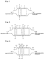
- Fig. 1 is a schematic sectional view showing one embodiment of the reformer according to the first aspect.
- the reformer comprises a heater unit 1 and a catalyst unit 2 disposed in a metallic casing 3 which forms a flow path of the reactant fluid.
- the heater unit 1 has electrodes 4, and electricity is supplied thereto from an external electric source not shown in Fig. 1.
- the heater unit 1 is disposed upstream of the catalyst unit 2.
- a reactant fluid A is fed into the reformer from an inlet 5, passes through the heater unit 1 and catalyst unit 2, and reaches an outlet 6.
- a fluid B containing the hydrogen produced leaves the outlet 6 and is transferred to a fuel cell section disposed downstream of the reformer.
- Both heater unit 1 and catalyst unit 2 are of honeycomb structure, their cell densities satisfying the relationship (1).
- one catalyst unit is disposed in the reformer.
- two or more catalyst units may be disposed.
- the intended effect of the present invention can be secured when the heater unit and at least one of the catalyst units downstream of the heater unit satisfy the relationship (1).
- the effect will be larger when the heater unit and the catalyst unit adjacent thereto satisfy the relationship (1), and still larger when the heater unit and all of the catalyst units downstream of the heater unit satisfy the relationship (1).
- the reformer according to the second aspect comprises two or more electrically heatable heater units of honeycomb structure in the flow path of a reactant fluid, and at least one catalyst unit of honeycomb structure capable of generating hydrogen from a reactant fluid containing an organic compound or carbon monoxide, by catalysis, at least at one position between the above heater units.
- the heater unit upstream of the catalyst unit has a high cell density to improve heat-exchanging efficiency between it and fluid.
- the heater unit downstream of the catalyst unit receives the fluid from the upstream-side heater unit and catalyst unit, both upstream of the downstream-side heater unit, and there are positioned the upstream-side heater unit and the catalyst unit at the upstream-side of the downstream-side heater unit, and the fluid being cooled by the upstream units.
- the downstream-side heater unit has a lower cell density than the upstream-side heater unit, to have a lower contact efficiency with the fluid than the upstream-side heater unit.
- the fluid flowing into the downstream-side heater contains hydrogen at a higher concentration than that flowing into the upstream-side heater. It is therefore preferable that the former fluid is not heated excessively for safety consideration and that the downstream-side heater unit has a lower cell density than the upstream-side heater unit.
- the reformer of the second aspect is characterized by at least one of the heater units upstream of the catalyst unit (upstream-side heater unit) and at least one of the heater units downstream of the catalyst unit (downstream-side heater unit) satisfying the following relationship (2): Cell density of the upstream-side heater unit ⁇ Cell density of the downstream-side heater unit
- Fig. 2 is a schematic sectional view showing one embodiment of the reformer of the second aspect.
- the reformer comprises an upstream-side heater unit 10, a catalyst unit 12, a downstream-side heater unit 11 and a catalyst unit 17, disposed in a metallic casing 13 which forms a flow path of the reactant fluid.
- Each of the upstream- and downstream-side heater units 10 and 11 has electrodes 14, and electricity is supplied thereto from an external electric source not shown in Fig. 2.
- the upstream-side heater unit 10 is disposed upstream of the catalyst unit 12, and the downstream-side heater unit 11 downstream of the catalyst unit 12.
- a reactant fluid A is fed into the reformer from an inlet 15, passes through the upstream-side heater unit 10, catalyst unit 12, downstream-side heater unit 11 and catalyst unit 17, and reaches an outlet 16.
- a fluid B containing the hydrogen produced leaves the outlet 16 and is transferred to a fuel cell section disposed downstream of the reformer
- Both upstream- and downstream-side heater units 10 and 11 are of honeycomb structure, their cell densities satisfying the relationship (2).
- two heater units are disposed in the flow path, an upstream-side heater unit and downstream-side heater unit with a catalyst unit in-between.
- three or more heater units may be disposed, with two or more upstream-side heater units and/or two or more downstream-side heater units.
- the intended effect of the present invention can be secured when at least one of the upstream-side heater units and at least one of the downstream-side heater units satisfy the relationship (2).
- the effect will be larger when the upstream-side heater unit and the downstream-side heater unit with no constitutional element (e.g., heater unit) except one or more catalyst units in-between satisfy the relationship (2).
- the reformer as the third aspect comprises two or more electrically heatable heater units of honeycomb structure adjacently disposed in the flow path of a reactant fluid in the flowing direction of the fluid, and at least one catalyst unit of honeycomb structure capable of generating hydrogen from a reactant fluid containing an organic compound or carbon monoxide, by catalysis.
- the fluid can be continuously and efficiently heated along the flow path from the upstream-side heater unit(s) to the downstream-side heater unit(s), when the downstream-side heater unit has a higher cell density, i.e., a higher heat-exchanging efficiency, than the upstream-side heater unit.
- the downstream-side heater unit has a lower heat-exchanging efficiency, i.e., a lower cell density, than the upstream-side heater unit, on the other hand, temperature of the fluid gained by the upstream-side heater unit at a cost may not be kept, or conversely lowered, by the downstream-side heater unit. It is therefore preferable, viewed from overall heating effect, that the downstream-side heater unit has a higher cell density than the upstream-side heater unit.
- Mixing efficiency of the reaction fluid between the heater units can be increased, when the upstream- and downstream-side heater units are different from each other in cell structure (shape and density) and the downstream heater unit has a finer cell structure, i.e., a higher cell density, than the upstream heater unit, and uneven temperature distribution in the heater unit or catalyst unit section can be reduced, when the downstream heater unit is followed by an adjacent heater unit or catalyst unit.
- the reformer of the third aspect is characterized by at least two adjacent heater units satisfying the following relationship (3): Cell density of the upstream-side heater unit ⁇ Cell density of the downstream-side heater unit
- Fig. 3 is a schematic sectional view showing one embodiment of the reformer of the third aspect.
- the reformer comprises an upstream heater unit 20, a downstream heater unit 21 and a catalyst unit 22, disposed in a metallic casing 23 which forms a flow path of the reactant fluid.
- Each of the upstream- and downstream-side heater units 20 and 21 has electrodes 24, and electricity is supplied thereto from an external electric source not shown in Fig. 3.
- the upstream heater unit 20 and downstream heater unit 21 are adjacent to each other in the flowing direction of the fluid and followed by the catalyst unit 22 downstream of these two heater units.
- a reactant fluid A is fed into the reformer from an inlet 25, passes through the upstream heater unit 20, downstream heater unit 21 and catalyst unit 22, and reaches an outlet 26.
- a fluid B containing the hydrogen produced leaves the outlet 26 and is transferred to a fuel cell section disposed downstream of the reformer.
- Both upstream- and downstream-side heater units 20 and 21 are of honeycomb structure, their cell densities satisfying the relationship (3).
- two adjacent heater units are disposed in the flow path.
- three or more adjacent heater units may be disposed.
- the intended effect of the present invention can be secured when at least two of the heater units satisfy the relationship (3).
- the effect will be larger when the most upstream heater unit and the heater unit adjacent thereto satisfy the relationship (3).
- the effect will be still larger when all of the adjacent heater units satisfy the relationship (3).
- a reactant fluid containing an organic compound such as hydrocarbon (e.g., butane or propane), or alcohol (e.g., methanol), or carbon monoxide (CO).
- hydrocarbon e.g., butane or propane
- alcohol e.g., methanol
- CO carbon monoxide
- a hydrocarbon is preferred in view of the transportation via a gas cylinder or pipe.
- a gasoline or alcohol e.g., methanol
- the starting material for obtaining hydrogen is not restricted to these. CO is not preferred as the starting material, because it is a toxic gas.
- the main reaction in the reformer of the present invention is a steam reforming reaction taking place in the presence of steam. Further, a CO shift reaction and selective CO oxidation reaction are allowed to take place to reduce CO (a by-product), in order to obtain high-purity hydrogen and alleviate the deactivation of the electrode of fuel cell by CO.
- An example of the reactions taking place when butane is used as a starting material, is shown below. (1) C 4 H 10 + 9H 2 O ⁇ 9H 2 + 4CO Steam reforming reaction (2) CO + H 2 O ⁇ CO 2 + H 2 CO shift reaction (3) CO + 1/2O 2 ⁇ CO 2 Selective CO oxidation reaction
- Hydrogen can also be obtained by using a partial oxidation reaction in place of the steam reforming reaction. (4) C 4 H 10 + 2O 2 ⁇ 4CO + 5H 2 Partial oxidation reaction
- the process for obtaining hydrogen based on the reaction (1) is called steam reforming
- the process for obtaining hydrogen based on the reaction (4) is called partial oxidation. Any of these processes is applicable to the present invention.
- Use of steam reforming or partial oxidation in hydrogen production is optional.
- partial oxidation is drawing attention when gasoline is used as the starting material
- steam reforming is drawing attention when an alcohol (e.g., methanol) is used as the starting material.
- steam reforming can produce high-purity hydrogen easily at lower temperature and is more efficient.
- the reactions (1), (5) and (6) are generally endothermic, and require temperature of 500°C or higher.
- the reactions (2) and (3) are exothermic, and are allowed to proceed at relatively low temperature of 300°C or lower.
- the reaction (4) is exothermic and requires temperature of 500°C or higher.
- the reactions (1) [or (5) or (6)], (2) and (3), or the reactions (4), (2) and (3) are conducted over respective catalysts being disposed in series in the flow path of a reactant fluid.
- the catalyst unit for the present invention contains at least one of the catalyst components having catalysis for the above-mentioned steam reforming, partial oxidation or decomposition, CO shift reaction, selective CO oxidation, etc.
- the selective CO oxidation reaction is for reduction in CO and has no direct relation to hydrogen production; however, when high-purity hydrogen is required, this reaction is important and allowed to proceed in the reformer, and the catalyst for the reaction is contained in the catalyst unit.
- the catalyst for generating hydrogen from a reactant fluid containing an organic compound or CO concrete examples of the preferable ones include a catalyst containing, as main components, a heat-resistant oxide and at least one kind of metal selected from the metal elements of groups VB to VIII, IB and IIB of the long-form periodic table.
- the metal element effective for steam reforming, partial oxidation or decomposition it is preferred to use a metal of group VIII as the essential metal element.
- the preferred metal elements are Ni, Rh, Ru, Ir, Pd, Pt, Co and Fe, and they are used singly or in combination. It is preferred to add thereto, as a promoter catalyst, V or Nb of group VB; Cr, Mo or W of group VIB; Mn or Re of group VIIB; or the like. Also, an alkaline earth metal may be added for prevention of carbonization.
- These metals are ordinarily loaded on a heat-resistant oxide, whereby the resulting catalyst can have an increased specific surface area, enhanced activity and durability to reaction temperature.
- the heat-resistant oxide there can be used Al 2 O 3 , SiO 2 , TiO 2 , ZrO 2 , MgO, zeolite, SAPO, ALPO, a layer structure compound or a compound oxide thereof.
- these oxides one having a specific surface area of ordinarily 5 to 300 m 2 /g is used.
- the heat-resistant oxide and the above-mentioned metal component are made into a uniform mixture by a known means such as chemical method (e.g., immersion, coprecipitation or sol-gel), physical mixing or the like.
- Specific surface of the synthesized catalyst is generally in a range from 5 to 300 m 2 /g.
- a specific surface area below 5 m 2 /g invites reduced activity, and that above 300 m 2 /g invites striking property change at high temperature and resultant reduction in durability.
- alumina Al 2 O 3
- spinel obtained by adding magnesia to alumina, or magnesia (which is a basic carrier) per se or a compound oxide thereof for suppressing carbonization.
- the proportion of the catalyst metal added to the heat-resistant oxide is preferably 1 to 30% by weight.
- the catalyst metal is a noble metal, addition of up to about 10% by weight is sufficient because the noble metal has a high activity.
- the catalyst metal is a base metal such as Ni, addition of 10 to 30% by weight is preferred.
- the catalyst appropriate for CO shift reaction there is often used Fe or Co of group VIII, Cu of group IB, Zn of group IIB, or the like.
- the metal elements specified in the present invention show a fairly high activity for CO shift reaction. Since the metals showing an activity at relatively low temperature include Cu, Zn or both, loading of such a metal or metal combination on the above-mentioned heat-resistant oxide (e.g., alumina) can assure high heat-resistance. In such a case, amount of the metal added to the heat-resistant oxide is preferably 10 to 50% by weight.
- spinel e.g., Fe-Cr
- the catalyst appropriate for selective CO oxidation reaction there can be mentioned metals such as Mn of group VII, Co and noble metals of group VIII, Cu, Ag and Au of group IB and the like. They can be used ordinarily by being loaded on the above-mentioned heat-resistant oxide. The catalyst need not oxidize hydrogen produced, and Pt or the like having a strong interactions with CO can be used. A hopcalite catalyst is also one of the preferred catalysts.
- the catalyst unit is used in the form of honeycomb structure, which may be made of a catalyst component(s) per se, or may be obtained by loading a catalyst component(s) on a honeycomb carrier made of an inert material such as cordierite, mullite or the like.
- the suitable materials for the honeycomb carrier include ceramics (e.g., cordierite and mullite), foil-shaped metals composed of heat-resistant stainless steel (e.g., Fe-Cr-Al alloy), and metallic materials formed into honeycomb structure by powder metallurgy.
- the honeycomb carrier is preferably porous, whether it is a ceramic or metal, for reduced heat capacity and improved catalyst-loading characteristics. Its porosity is preferably in a range from 0.5 to 50%, more preferably 10 to 40%.
- thickness of the coating layer is preferably in a range from 5 to 100 micron. Thickness below 5 micron may invite catalyst deactivation, whereas that above 100 micron increased pressure loss.
- the catalyst unit is constituted by arranging, generally in series, a catalyst for steam reforming, partial oxidation or decomposition, a catalyst for CO shift reaction, and a catalyst for selective CO oxidation.
- the catalyst unit may be obtained by loading respective catalysts on different areas of one honeycomb structure; however, since each catalyst has a different operating temperature, it is preferred to arrange a plurality of catalyst units, each containing a different catalyst, in the reformer.
- the heater unit for the present invention also has a honeycomb structure, like the catalyst unit. It may be made of an electrically heatable material per se; however, in view of the warm-up property and reaction acceleration during cold start-up and temperature stabilization of the catalyst unit during steady-state operation, the heater unit preferably contains at least one of the catalyst components having catalysis for the above-mentioned steam reforming, partial oxidation or decomposition, CO shift reaction, selective CO oxidation, etc.
- the catalyst presence in the heater unit may be achieved by mixing the catalyst(s) with the electrically heatable material (compositing), or more preferably achieved by loading the catalyst(s) on the electrically heatable material. In view of the reaction activity expected, most preferred is a heater unit obtained by loading the catalyst(s) on the honeycomb structure having electrical heatability.
- the catalyst component for the heater unit may be the same as, or different from, that for the catalyst unit.
- a sintered material having electrical resistance-heatability for example, barium titanate (of so-called PTC, a substance having a positive resistance characteristic), carbide (e.g., SiC or MoSi 2 ), superconductive oxide of Y or Bi type, perovskite showing a negative resistance characteristic, oxygen ion-conductive material (e.g., ZrO 2 ), silicide, boride, nitride, or ion-conductive glass although this is not a sintered material.
- barium titanate of so-called PTC, a substance having a positive resistance characteristic
- carbide e.g., SiC or MoSi 2
- superconductive oxide of Y or Bi type e.g., perovskite showing a negative resistance characteristic
- oxygen ion-conductive material e.g., ZrO 2
- silicide boride, nitride, or ion-conductive glass although this is not a sintered material.
- a metal having electrical resistance-heatability such as Fe-Cr-Al ferrite composition or other alloy composition (e.g., Ni-Cr, Fe-Al, Fe-Cr or Ni-Al); or a cermet which is a composite material of the above metal and a heat-resistant material having no electrical resistance-heatability (e.g., alumina).
- any material for the heater unit can be used singly or in the form of composite material of two or more kinds, or may be used as a composite material with a catalyst component(s).
- any material for the heater unit must have electrical heatability, and there is no other restriction as to kind of the material.
- An alloy composition such as Fe-Cr-Al, Fe-Al, Fe-Cr or the like is preferred in view of the cost and easy production.
- These alloys are already in commercial use in catalytic converters for automobiles, and have various advantages in that they have excellent heat resistance and thermal shock and can be easily made into a honeycomb structure by rolling or powder metallurgy. Examples of the honeycomb structures are disclosed by, e.g., Japanese Patent Application Kokai (Laid-Open) No. 295184/1991 (Fig. 20) and National Publication of International Patent Application No. 500911/1991 (Fig. 21).
- the heater unit To the heater unit are connected electrodes for electrifying the unit, and electricity is supplied thereto from an external electric source.
- the electric source can be a battery, alternator, capacitor (condenser) or the like.
- a plurality of heater units When a plurality of heater units are disposed in the reformer, they may be independently connected to the electric sources, or arranged in series or parallel to be connected to one source.
- the resistance In the heater unit, the resistance must be adjusted depending upon the power supplied, voltage used, etc. There is no restriction as the adjustment of the resistance; however, when the heater unit is a honeycomb structure, the adjustment can be made by forming slits or gaps therein, as disclosed by Japanese Patent Application Kokai (Laid-Open) No. 295184/1991 and National Publication of International Patent Application No. 500911/1991.
- Both catalyst unit and heater unit preferably have a cell density of 4 to 2000 cells/in 2 (cpsi), more preferably 50 to 1500 cpsi, to satisfy the condition for each of the first to the third aspects.
- Cell density below 4 cpsi may invite insufficient contact efficiency and hence insufficient unit function (heating for the heater unit and catalytic reaction for the catalyst unit).
- Cell density above 2000 cpsi may invite an excessive pressure loss.
- the cell section can be of any shape, e.g., circular, square, polygonal or corrugated.
- the heater units A to I were produced by the following procedures. (Heater Unit A)
- Powdered Fe, Cr-30Al (wt.%), Fe-50Al (wt.%), Fe-20B (wt.%) and Y 2 O 3 all having an average particle size of 44 micron or less, were mixed to have a composition of Fe-16Cr-8Al-0.05B-0.5Y 2 O 3 , and 100 g of the mixture was incorporated with 4 g of methyl cellulose as the organic binder and 1 g of oleic acid as the oxidation inhibitor.
- the mixture thus prepared was extruded into a cylindrical honeycomb structure, which was dried at 90°C for 16 h in air, sintered at 1325°C for 2 h in a hydrogen atmosphere, and thermally treated at 1150°C for 30 min in air.
- the honeycomb structure produced by the above procedure had an outer diameter of 93 mm, thickness of 30 mm, thickness of partition wall of 0.1 mm (approximately 4 mil), and cell density of 400 cpsi (hexagonal cells). It was provided with slits, to allow rapid heating of the central portion, to produce the honeycomb heater (Fig. 20).
- the honeycomb heater was then provided with electrodes, and disposed in a metallic casing of stainless steel while kept insulated from the casing, to produce the heater unit A. It has an effective volume of 0.2 L.
- the heater unit B was produced in a manner similar to that for the heater unit A, except that the honeycomb structure had a cell density of 600 cpsi.
- the heater unit D of honeycomb structure carrying the catalyst component for steam reforming was produced in a manner similar to that for the heater unit C, except that the honeycomb structure on which the slurry was loaded had a cell density of 300 cpsi.
- the heater unit E of honeycomb structure carrying the catalyst component for steam reforming was produced in a manner similar to that for the heater unit C, except that the honeycomb structure on which the slurry was loaded had a cell density of 500 cpsi.
- the heater unit G of honeycomb structure carrying the catalyst component for CO shift reaction was produced in a manner similar to that for the heater unit F, except that the honeycomb structure on which the slurry was loaded had a cell density of 300 cpsi.
- the heater unit H of honeycomb structure carrying the catalyst component for CO shift reaction was produced in a manner similar to that for the heater unit F, except that the honeycomb structure on which the slurry was loaded had a cell density of 600 cpsi.
- the catalyst units A to N were produced by the following procedures. All of the catalyst units had a common quantity of the catalyst component per unit volume of the honeycomb structure. Since Al 2 O 3 accounted for most of the catalyst component, its heat capacity per unit volume of the honeycomb structure on which it was loaded was essentially the same.
- honeycomb structure cell density: 600 cpsi, volume: 1.0 L, outer diameter: 93 mm, thickness of partition wall: 0.15 mm (approximately 6 mil), cell shape: hexagonal) of cordierite (NGK Insulators, Ltd.).
- the slurry-loaded honeycomb structure was sintered at 500°C, to produce the catalyst unit A carrying the catalyst component for steam reforming.
- the catalyst unit B of honeycomb structure carrying the catalyst component for steam reforming was produced in a manner similar to that for the catalyst unit A, except that the honeycomb structure on which the slurry was loaded had a cell density of 400 cpsi.
- the catalyst unit C of honeycomb structure carrying the catalyst component for steam reforming was produced in a manner similar to that for the catalyst unit A, except that the honeycomb structure on which the slurry was loaded had a volume of 0.8 L.
- the catalyst unit D of honeycomb structure carrying the catalyst component for steam reforming was produced in a manner similar to that for the catalyst unit A, except that the honeycomb structure on which the slurry was loaded had a volume of 0.6 L.
- the catalyst unit E of honeycomb structure carrying the catalyst component for steam reforming was produced in a manner similar to that for the catalyst unit A, except that the honeycomb structure on which the slurry was loaded had a cell density of 300 cpsi and volume of 0.8 L.
- the catalyst unit F of honeycomb structure carrying the catalyst component for steam reforming was produced in a manner similar to that for the catalyst unit A, except that the honeycomb structure on which the slurry was loaded had a cell density of 300 cpsi and volume of 0.6 L.
- honeycomb structure cell density: 600 cpsi, volume: 1.0 L, outer diameter: 93 mm, thickness of partition wall: 0.15 mm (approximately 6 mil), cell shape: hexagonal) of cordierite (NGK Insulator, Ltd.).
- the slurry-loaded honeycomb structure was sintered at 500°C, to produce the catalyst unit G carrying the catalyst component for CO shift reaction.
- the catalyst unit H of honeycomb structure carrying the catalyst component for CO shift reaction was produced in a manner similar to that for the catalyst unit G, except that the honeycomb structure on which the slurry was loaded had a cell density of 400 cpsi.
- the catalyst unit I of honeycomb structure carrying the catalyst component for CO shift reaction was produced in a manner similar to that for the catalyst unit G, except that the honeycomb structure on which the slurry was loaded had a volume of 0.8 L.
- the catalyst unit J of honeycomb structure carrying the catalyst component for CO shift reaction was produced in a manner similar to that for the catalyst unit G, except that the honeycomb structure on which the slurry was loaded had a cell density of 400 cpsi and volume of 0.8 L.
- the catalyst unit K of honeycomb structure carrying the catalyst component for CO shift reaction was produced in a manner similar to that for the catalyst unit G, except that the honeycomb structure on which the slurry was loaded had a cell density of 400 cpsi and volume of 0.6 L.
- the same slurry as that used for producing the heater unit C was loaded on the upper half of a carrier of honeycomb structure (cell density: 600 cpsi, volume: 2.0 L, outer diameter: 93 mm, thickness of partition wall: 0.15 mm (approximately 6 mil), cell shape: hexagonal) of cordierite (NGK Insulator, Ltd.), and the same slurry as that used for producing the heater unit F was loaded on the lower half of the above carrier.
- the slurry-loaded honeycomb structure was sintered at 500°C, to produce the catalyst unit L carrying the catalyst components for steam reforming and CO shift reaction at different positions on the same carrier.
- honeycomb structure cell density: 600 cpsi, volume: 1.0 L, outer diameter: 93 mm, thickness of partition wall: 0.15 mm (approximately 6 mil), cell shape: hexagonal) of cordierite (NGK Insulator, Ltd.).
- the slurry-loaded honeycomb structure was sintered at 500°C, to produce the catalyst unit M carrying the catalyst component for selective CO oxidation.
- the catalyst unit N of honeycomb structure carrying the catalyst component for selective CO oxidation was produced in a manner similar to that for the catalyst unit M, except that the honeycomb structure on which the slurry was loaded had a cell density of 400 cpsi.
- the catalyst unit O of honeycomb structure carrying the catalyst component for selective CO oxidation was produced in a manner similar to that for the catalyst unit M, except that the honeycomb structure on which the slurry was loaded had a volume of 0.8 L.
- the reformer A comprised the heater unit A(30), catalyst unit A(40), catalyst unit G(46) and catalyst unit M(52) in this order in the flow path from the upstream (Fig. 4).
- the reformer B comprised the heater unit A(30), catalyst unit A(40), catalyst unit H(47) and catalyst unit N(53) in this order in the flow path from the upstream (Fig. 5).
- the reformer C comprised the heater unit B(31), catalyst unit B(41), catalyst unit H(47) and catalyst unit N(53) in this order in the flow path from the upstream (Fig. 6).
- the reformer D comprised the heater unit A(30), catalyst unit B(41), catalyst unit H(47) and catalyst unit N(53) in this order in the flow path from the upstream (Fig. 7).
- the reformer E comprised the heater unit C(32), catalyst unit C(42), catalyst unit H(47) and catalyst unit N(53) in this order in the flow path from the upstream (Fig. 8).
- the reformer F comprised the heater unit A(30), catalyst unit L(51) and catalyst unit M(52) in this order in the flow path from the upstream (Fig. 9).
- the reformer G comprised the heater unit C(32), catalyst unit C(42), heater unit G(36), catalyst unit J(49) and catalyst unit N(53) in this order in the flow path from the upstream (Fig. 10).
- the reformer H comprised the heater unit C(32), catalyst unit E(44), heater unit G(36), catalyst unit J(49) and catalyst unit N(53) in this order in the flow path from the upstream (Fig. 11).
- the reformer I comprised the heater unit C(32), catalyst unit C(42), heater unit H(37), catalyst unit J(49) and catalyst unit N(53) in this order in the flow path from the upstream (Fig. 12).
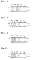
- the reformer J comprised the heater unit C(32), heater unit E(34), catalyst unit D(43), catalyst unit H(47) and catalyst unit N(53) in this order in the flow path from the upstream (Fig. 13).
- the reformer K comprised the heater unit C(32), heater unit E(34), catalyst unit F(45), catalyst unit H(47) and catalyst unit N(53) in this order in the flow path from the upstream (Fig. 14).
- the reformer L comprised the heater unit C(32), heater unit D(33), catalyst unit D(43), catalyst unit H(47) and catalyst unit N(53) in this order in the flow path from the upstream (Fig. 15).
- the reformer M comprised the heater unit C(32), heater unit E(34), catalyst unit D(43), heater unit G(36), catalyst unit J(49) and catalyst unit N(53) in this order in the flow path from the upstream (Fig. 16).
- the reformer N comprised the heater unit C(32), heater unit D(33), catalyst unit D(43), heater unit H(37), catalyst unit J(49) and catalyst unit N(53) in this order in the flow path from the upstream (Fig. 17).
- the reformer O comprised the heater unit C(32), catalyst unit C(42), heater unit G(36), heater unit F(35), catalyst unit K(50) and catalyst unit N(53) in this order in the flow path from the upstream (Fig. 18).
- the reformer P comprised the heater unit C(32), catalyst unit C(42), heater unit G(36), catalyst unit I(48), heater unit I(38) and catalyst unit O(54) in this order in the flow path from the upstream (Fig. 19).
- a mixture of methanol (CH 3 OH) and water was fed to each of the above reformers A to P at a constant rate, where the steam carbon ratio (S/C) in the starting mixture was set at 2.0.
- Electricity was supplied to each heater unit, to a total power of 2.5 kW, where supply of electricity and that of the starting mixture to each reformer were started at the same time. Electricity was supplied continuously to the heater unit upstream of the catalyst unit carrying the catalyst component for steam reforming and to the heater unit carrying the catalyst component for steam reforming while the starting mixture was fed, because of the endothermic nature of steam reforming.
- supply of electricity to that heater unit was stopped when it reached 300°C, because of the exothermic nature of the reaction.
- air was fed to the system between these catalyst units, to supply oxygen required by the latter.
- the reformer of the present invention is improved in, e.g., contact efficiency between the catalyst unit and reactant fluid, and heat-exchanging efficiency of the heater units, resulting in improved efficiency for production of hydrogen and reduction in CO as the by-product.
Landscapes
- Chemical & Material Sciences (AREA)
- Chemical Kinetics & Catalysis (AREA)
- Organic Chemistry (AREA)
- Engineering & Computer Science (AREA)
- Health & Medical Sciences (AREA)
- General Health & Medical Sciences (AREA)
- Combustion & Propulsion (AREA)
- Inorganic Chemistry (AREA)
- Life Sciences & Earth Sciences (AREA)
- Manufacturing & Machinery (AREA)
- Sustainable Development (AREA)
- Sustainable Energy (AREA)
- Electrochemistry (AREA)
- General Chemical & Material Sciences (AREA)
- Hydrogen, Water And Hydrids (AREA)
- Fuel Cell (AREA)
- Catalysts (AREA)
Claims (16)
- Dispositif de reformage disposé dans le chemin d'écoulement d'un fluide réagissant, qui comprend:une unité de chauffage (1, 10, 11, 20, 21, 30-38) pouvant être chauffée électriquement en une structure en nid d'abeilles; etau moins une unité de catalyseur (2, 12, 17, 22, 40-54) d'une structure en nid d'abeilles apte à produire de l'hydrogène à partir d'un fluide réagissant contenant un composé organique ou un monoxyde de carbone, par catalyse, en aval dans le chemin d'écoulement du fluide de ladite unité de chauffage, où l'unité de chauffage et l'unité de catalyseur ou au moins l'une des unités de catalyseur satisfont à la relation suivante:Densité de cellules de l'unité de chauffage ≤ Densité de cellules de l'unité de catalyseur.
- Dispositif de reformage selon la revendication 1, où plusieurs desdites unités de catalyseur sont prévues, et ladite unité de chauffage et l'unité de catalyseur adjacente à celle-ci satisfont à la relation suivante:Densité de cellules de l'unité de chauffage < Densité de cellules de l'unité de catalyseur.
- Dispositif de reformage selon la revendication 1, où plusieurs desdites unités de catalyseur sont réalisées, et ladite unité de chauffage et toutes les unités de catalyseur en aval de ladite unité de chauffage satisfont à la relation suivante:Densité de cellules de l'unité de chauffage ≤ Densité de cellules de l'unité de catalyseur.
- Dispositif de reformage disposé dans le chemin d'écoulement d'un fluide réagissant, qui comprend:deux unités de chauffage pouvant être chauffées électriquement ou plus (10, 11, 32-38) d'une structure en nids d'abeilles; etau moins une unité de catalyseur (12, 17, 42, 43, 44, 48, 49) d'une structure en nid d'abeilles apte à produire de l'hydrogène à partir d'un fluide réagissant contenant un composé organique ou un monoxyde de carbone, par catalyse, agencée entre lesdites unités de chauffage dans le chemin d'écoulement de fluide, où au moins l'une des unités de chauffage en amont de l'unité de catalyseur (unité de chauffage côté amont) et au moins l'une des unités de chauffage en aval de l'unité de catalyseur (unité de chauffage côté aval) satisfont à la relation suivante:Densité de cellules de l'unité de chauffage côté amont ≥ Densité de cellules de l'unité de chauffage côté aval.
- Dispositif de reformage selon la revendication 4, où l'unité de chauffage côté amont et l'unité de chauffage côté aval qui n'ont pas d'élément excepté un ou plusieurs desdites unités de catalyseur entre elles satisfont à la relation:Densité de cellules de l'unité de chauffage côté amont ≥ Densité de cellules de l'unité de chauffage côté aval.
- Dispositif de reformage selon la revendication 4, où trois desdites unités de chauffage ou plus sont réalisées avec lesdites unités de catalyseur entre chaque paire de celles-ci, et l'unité de chauffage côté amont et l'unité de chauffage côté aval par rapport à l'unité de catalyseur la plus amont satisfont à la relation:Densité de cellules de l'unité de chauffage côté amont ≥ Densité de cellules de l'unité de chauffage côté aval.
- Dispositif de reformage selon la revendication 4, où trois desdites unités de chauffage ou plus sont réalisées avec lesdites unités de catalyseur entre chaque paire de celles-ci, et chaque paire de celles-ci qui constitue lesdites unités de chauffage côté amont et côté aval par rapport à un catalyseur précité satisfont à la relation:Densité de cellules de l'unité de chauffage côté amont ≥ Densité de cellules de l'unité de chauffage côté aval.
- Dispositif de reformage disposé dans le chemin d'écoulement d'un fluide réagissant, qui comprend:deux unités de chauffage ou plus pouvant être chauffées électriquement (20, 21, 32-36) d'une structure en nid d'abeilles, agencées d'une manière adjacente les unes aux autres dans la direction de l'écoulement du fluide etau moins une unité de catalyseur (22, 43, 50) d'une structure en nid d'abeilles apte à produire de l'hydrogène à partir d'un fluide réagissant contenant un composé organique ou un monoxyde de carbone, par catalyse, où deux desdites unités de chauffage adjacentes satisfont à la relation suivante:Densité de cellules de l'unité de chauffage côté amont ≤ Densité de cellules de l'unité de chauffage côté aval.
- Dispositif de reformage selon la revendication 8, où ladite unité de chauffage à la position la plus amont et ladite unité de chauffage adjacente à celle-ci satisfont à la relation lorsque trois desdites unités de chauffage adjacentes ou plus sont installées dans la direction de l'écoulement du fluide:Densité de cellules de l'unité de chauffage côté amont < Densité de cellules de l'unité de chauffage côté aval.
- Dispositif de reformage selon la revendication 8, où toutes les unités de chauffage adjacentes précitées satisfont à la relation lorsque trois desdites unités de chauffage adjacentes ou plus sont installées dans la direction de l'écoulement du fluide:Densité de cellules de l'unité de chauffage côté amont ≤ Densité de cellules de l'unité de chauffage côté aval.
- Dispositif de reformage selon l'une des revendications précédentes, où ladite unité de catalyseur contient un ou plusieurs composants de catalyseur pour leur reformage de la vapeur, l'oxydation ou la décomposition partielle, et/ou la conversion catalytique de CO et/ou l'oxydation sélective de CO.
- Dispositif de reformage selon la revendication 11, où ledit composant de catalyseur contient, comme ingrédients principaux, un oxyde résistant à la chaleur et au moins un élément de métal sélectionné parmi ceux des groupes VB à VIII, IB et IIB de la table périodique de forme longue.
- Dispositif de reformage selon la revendication 12, où le ou chacun desdits éléments de métal est sélectionné parmi les éléments de métal des groupes VIII, V, Cr, Mo, W, Re, les éléments de métal du groupe IB et Zn.
- Dispositif de reformage selon la revendication 12, où ledit oxyde résistant à la chaleur est sélectionné parmi Al2O3, SiO2, TiO2, ZrO2, MgO, zéolite, SAPO (silicoalumino-phosphate) ALPO (aluminophosphate) et un oxyde composé à structure à couches de ceux-ci.
- Dispositif de reformage selon l'une des revendications précédentes, où ladite unité de chauffage contient un ou plusieurs des composants de catalyseur pour le reformage de la vapeur, l'oxydation ou la décomposition partielle, et/ou la conversion catalytique de CO et/ou l'oxydation sélective de CO.
- Dispositif de reformage selon l'une des revendications précédentes, où ladite unité de chauffage est constituée d'un matériau fritté ou métallique présentant une aptitude au chauffage par résistance électrique ou un composite de celui-ci, ou un composite d'un matériau résistant à la chaleur ne présentant pas d'aptitude au chauffage par résistance électrique et ledit matériau fritté ou métallique.
Applications Claiming Priority (2)
| Application Number | Priority Date | Filing Date | Title |
|---|---|---|---|
| JP18301398 | 1998-06-29 | ||
| JP10183013A JP2000007301A (ja) | 1998-06-29 | 1998-06-29 | 改質反応装置 |
Publications (2)
| Publication Number | Publication Date |
|---|---|
| EP0967174A1 EP0967174A1 (fr) | 1999-12-29 |
| EP0967174B1 true EP0967174B1 (fr) | 2003-05-28 |
Family
ID=16128221
Family Applications (1)
| Application Number | Title | Priority Date | Filing Date |
|---|---|---|---|
| EP99305137A Expired - Lifetime EP0967174B1 (fr) | 1998-06-29 | 1999-06-29 | Dispositif de reformage |
Country Status (4)
| Country | Link |
|---|---|
| US (1) | US6585940B2 (fr) |
| EP (1) | EP0967174B1 (fr) |
| JP (1) | JP2000007301A (fr) |
| DE (1) | DE69908242T2 (fr) |
Cited By (2)
| Publication number | Priority date | Publication date | Assignee | Title |
|---|---|---|---|---|
| CN101049908B (zh) * | 2006-04-05 | 2011-05-25 | 气体产品与化学公司 | 重整装置和合成气产生方法 |
| US12607140B2 (en) | 2019-10-25 | 2026-04-21 | ECC TEC MSJ Incorporated | Exhaust system and features thereof |
Families Citing this family (57)
| Publication number | Priority date | Publication date | Assignee | Title |
|---|---|---|---|---|
| US6488838B1 (en) * | 1999-08-17 | 2002-12-03 | Battelle Memorial Institute | Chemical reactor and method for gas phase reactant catalytic reactions |
| DE19944540B4 (de) | 1999-09-17 | 2005-01-13 | Daimlerchrysler Ag | Reaktorsystem mit elektrischen Heizmitteln |
| DE10023410A1 (de) * | 2000-05-12 | 2001-11-15 | Linde Gas Ag | Verfahren zur Erzeugung eines CO- und H2-haltigen Behandlungsgases für die Wärmebehandlung von metallischem Gut, Gasgenerator und Wärmebehandlungsanlage |
| MXPA03004998A (es) * | 2000-12-05 | 2003-09-05 | Texaco Development Corp | Procesador de combustible compacto para producir gas rico en hidrogeno. |
| DE10061084A1 (de) * | 2000-12-08 | 2002-07-04 | Emitec Emissionstechnologie | Reformeranlage mit Wärmeschild |
| JP2002306915A (ja) † | 2001-02-09 | 2002-10-22 | Denso Corp | ハニカム構造体 |
| JP4401587B2 (ja) * | 2001-03-08 | 2010-01-20 | 本田技研工業株式会社 | 改質装置の掃気方法 |
| JP3863774B2 (ja) | 2001-12-19 | 2006-12-27 | 三洋電機株式会社 | 燃料電池システム |
| US20040016650A1 (en) * | 2002-07-29 | 2004-01-29 | Klug Karl H. | Electrocatalytic reformer for synthesis gas production |
| US6622519B1 (en) * | 2002-08-15 | 2003-09-23 | Velocys, Inc. | Process for cooling a product in a heat exchanger employing microchannels for the flow of refrigerant and product |
| US7014835B2 (en) | 2002-08-15 | 2006-03-21 | Velocys, Inc. | Multi-stream microchannel device |
| US6969505B2 (en) * | 2002-08-15 | 2005-11-29 | Velocys, Inc. | Process for conducting an equilibrium limited chemical reaction in a single stage process channel |
| CA2410927A1 (fr) * | 2002-11-05 | 2004-05-05 | Michel Petitclerc | Reacteur a chauffage electrique pour le reformage en phase gazeuse |
| US7105148B2 (en) | 2002-11-26 | 2006-09-12 | General Motors Corporation | Methods for producing hydrogen from a fuel |
| US7208136B2 (en) * | 2003-05-16 | 2007-04-24 | Battelle Memorial Institute | Alcohol steam reforming catalysts and methods of alcohol steam reforming |
| US8747805B2 (en) * | 2004-02-11 | 2014-06-10 | Velocys, Inc. | Process for conducting an equilibrium limited chemical reaction using microchannel technology |
| US7544342B2 (en) * | 2004-08-25 | 2009-06-09 | The Boc Group, Inc. | Hydrogen production process |
| KR100673747B1 (ko) * | 2005-03-04 | 2007-01-24 | 삼성에스디아이 주식회사 | 분사노즐 조립체 및 이를 구비한 연료전지 시스템 |
| JP4462082B2 (ja) | 2005-03-22 | 2010-05-12 | トヨタ自動車株式会社 | 燃料改質装置 |
| JP4956946B2 (ja) * | 2005-09-16 | 2012-06-20 | 三菱マテリアル株式会社 | 燃料電池 |
| US20070084116A1 (en) * | 2005-10-13 | 2007-04-19 | Bayerische Motoren Werke Aktiengesellschaft | Reformer system having electrical heating devices |
| US7829035B2 (en) * | 2006-01-19 | 2010-11-09 | Massachusetts Institute Of Technology | Oxidation catalyst |
| US7736399B2 (en) * | 2006-11-07 | 2010-06-15 | Delphi Technologies, Inc. | Electrically-heated metal vaporizer for fuel/air preparation in a hydrocarbon reformer assembly |
| DE102007010758A1 (de) * | 2007-03-06 | 2008-09-11 | Emitec Gesellschaft Für Emissionstechnologie Mbh | Elektrisch beheizbarer Wabenkörper und Verfahren zu dessen Betrieb |
| DE102008050817A1 (de) * | 2008-10-08 | 2010-04-15 | Karl-Heinz Tetzlaff | Abgasfreie allotherme Dampfreformierung |
| US8727050B2 (en) * | 2009-02-25 | 2014-05-20 | GM Global Technology Operations LLC | System and method for controlling an electrically heated catalyst for a hybrid vehicle |
| FR2944519B1 (fr) * | 2009-04-21 | 2011-08-26 | Irma | Module et dispositif de reformage catalytique, et procedes de fabrication |
| US8359844B2 (en) * | 2009-08-07 | 2013-01-29 | GM Global Technology Operations LLC | Radiant heating systems and methods for catalysts of exhaust treatment systems |
| US9458812B2 (en) * | 2009-09-02 | 2016-10-04 | GM Global Technology Operations LLC | Engine control systems and methods for minimizing fuel consumption |
| US9410458B2 (en) * | 2009-10-01 | 2016-08-09 | GM Global Technology Operations LLC | State of charge catalyst heating strategy |
| JP6231697B2 (ja) | 2013-11-06 | 2017-11-15 | ワット・フューエル・セル・コーポレイションWatt Fuel Cell Corp. | 液体燃料cpox改質器及びcpox改質の方法 |
| EP3065861A2 (fr) | 2013-11-06 | 2016-09-14 | Watt Fuel Cell Corp. | Réacteur chimique doté d'un collecteur pour la régulation de l'écoulement d'un fluide réactionnel gazeux entrant |
| WO2015069621A2 (fr) | 2013-11-06 | 2015-05-14 | Watt Fuel Cell Corp. | Reformeur |
| WO2015069836A2 (fr) | 2013-11-06 | 2015-05-14 | Watt Fuel Cell Corp. | Reformeurs cpox de combustible gazeux et procédés de reformage cpox |
| KR101891544B1 (ko) | 2013-11-06 | 2018-08-24 | 와트 퓨얼 셀 코퍼레이션 | 일체화된 기체 연료 촉매부분산화 개질장치 및 연료전지 시스템, 및 전기 생산 방법 |
| WO2015069754A2 (fr) | 2013-11-06 | 2015-05-14 | WATT Fuel Cell Corp | Reformeur cpox de combustible liquide et systèmes de piles à combustible, et procédés de production d'électricité |
| EP3423686A1 (fr) * | 2016-03-02 | 2019-01-09 | Watlow Electric Manufacturing Company | Accumulateur thermique destiné à être utilisé dans un système d'écoulement de fluide |
| EP3574991A1 (fr) | 2018-05-31 | 2019-12-04 | Haldor Topsøe A/S | Reformage à la vapeur chauffée par un chauffage à résistance |
| WO2019228798A1 (fr) | 2018-05-31 | 2019-12-05 | Haldor Topsøe A/S | Réactions endothermiques chauffées par chauffage par résistance |
| CA3099617C (fr) | 2018-05-31 | 2025-02-11 | Topsoe A/S | Production d’hydrogène par reformage de méthane à la vapeur |
| KR102917527B1 (ko) | 2018-08-21 | 2026-01-27 | 셰브런 유.에스.에이.인크. | 방향족 탄화수소를 제조하기 위한 촉매 개질 공정 및 시스템 |
| CN109279573B (zh) * | 2018-09-30 | 2022-03-22 | 中石化宁波工程有限公司 | 一种配套水煤浆气化的等温变换工艺 |
| CA3155515A1 (fr) | 2019-10-01 | 2021-04-08 | Haldor Topsoe A/S | Hydrogene a la demande a partir de methanol |
| KR20220077135A (ko) | 2019-10-01 | 2022-06-08 | 할도르 토프쉐 에이/에스 | 맞춤형 합성 가스 |
| JP7662621B2 (ja) | 2019-10-01 | 2025-04-15 | トプソー・アクチエゼルスカベット | シアン化物オンデマンド |
| AU2020360477A1 (en) | 2019-10-01 | 2022-03-03 | Haldor Topsøe A/S | On demand hydrogen from ammonia |
| CN119660676A (zh) | 2019-10-01 | 2025-03-21 | 托普索公司 | 由甲醇按需生产合成气 |
| KR20220069071A (ko) | 2019-10-01 | 2022-05-26 | 할도르 토프쉐 에이/에스 | 해안 개질 설비 또는 선박 |
| WO2021080651A1 (fr) * | 2019-10-25 | 2021-04-29 | ECC TEC MSJ Incorporated | Système d'échappement et ses caractéristiques |
| WO2021080627A1 (fr) * | 2019-10-25 | 2021-04-29 | ECC TEC MSJ Incorporated | Convertisseur catalytique |
| FR3102507B1 (fr) * | 2019-10-28 | 2021-11-19 | Faurecia Systemes Dechappement | Dispositif de chauffage de gaz d’échappement, ligne d’échappement et véhicule associés |
| CA3160620A1 (fr) | 2019-11-12 | 2021-05-20 | Haldor Topsoe A/S | Vapocraqueur electrique |
| CN112871161B (zh) * | 2021-02-20 | 2022-09-09 | 浙江工业大学上虞研究院有限公司 | 一种苯选择加氢制环己烯用催化剂的制备方法 |
| WO2022264514A1 (fr) * | 2021-06-18 | 2022-12-22 | 日本碍子株式会社 | Élément chauffant avec couche comprenant un matériau fonctionnel, unité chauffante avec couche comprenant un matériau fonctionnel, système de purification d'intérieur de véhicule, et structure en nid d'abeilles |
| CA3228841A1 (fr) | 2021-08-13 | 2023-02-16 | Saban Akyildiz | Systeme d'echappement et ses composants |
| KR102817773B1 (ko) * | 2022-09-06 | 2025-06-10 | 한국에너지기술연구원 | 암모니아를 이용한 고순도 수소 제조장치 및 제조방법 |
| US12366188B1 (en) | 2025-04-09 | 2025-07-22 | ECC TEC MSJ Incorporated | Heater for exhaust pollution mitigation |
Family Cites Families (15)
| Publication number | Priority date | Publication date | Assignee | Title |
|---|---|---|---|---|
| US4365952A (en) * | 1979-03-20 | 1982-12-28 | Matsushita Electric Industrial Co., Ltd. | Liquid gas burner |
| JPS58219945A (ja) * | 1982-06-15 | 1983-12-21 | Matsushita Electric Ind Co Ltd | 炭化水素改質用触媒 |
| US5023276A (en) | 1982-09-30 | 1991-06-11 | Engelhard Corporation | Preparation of normally liquid hydrocarbons and a synthesis gas to make the same, from a normally gaseous hydrocarbon feed |
| DE8816514U1 (de) | 1988-04-25 | 1989-10-26 | Emitec Gesellschaft für Emissionstechnologie mbH, 5204 Lohmar | Elektrisch beheizbarer Katalysator-Trägerkörper |
| JP2931362B2 (ja) | 1990-04-12 | 1999-08-09 | 日本碍子株式会社 | 抵抗調節型ヒーター及び触媒コンバーター |
| JPH0521084A (ja) * | 1991-07-17 | 1993-01-29 | Fuji Electric Co Ltd | ユニツト組立型燃料電池発電システム |
| GB2268694A (en) | 1992-07-14 | 1994-01-19 | Rolls Royce Plc | A catalytic combustion chamber |
| US5465573A (en) * | 1992-07-29 | 1995-11-14 | Ngk Insulators, Ltd. | Multi-stage honeycomb heater |
| DE4230090C2 (de) | 1992-09-09 | 1995-12-07 | Heidelberger Druckmasch Ag | Farbwerk für eine Druckmaschine |
| ATE158845T1 (de) * | 1993-05-25 | 1997-10-15 | Grace W R & Co | Kombinierter, elektrisch heizbarer umwandler |
| JP3526084B2 (ja) * | 1993-12-28 | 2004-05-10 | 日本碍子株式会社 | 排ガス浄化用吸着・触媒体、吸着体、排ガス浄化システム及び排ガス浄化方法 |
| JP3599370B2 (ja) | 1994-05-23 | 2004-12-08 | 日本碍子株式会社 | 水素製造装置 |
| JP3403494B2 (ja) | 1994-05-23 | 2003-05-06 | 日本碍子株式会社 | 改質反応器 |
| US5702838A (en) * | 1995-08-18 | 1997-12-30 | Matsushita Electric Industrial Co., Ltd. | Fuel cell device equipped with catalyst material for removing carbon monoxide and method for removing carbon monoxide |
| JPH11130405A (ja) | 1997-10-28 | 1999-05-18 | Ngk Insulators Ltd | 改質反応装置、触媒装置、それらに用いる発熱・触媒体、及び改質反応装置の運転方法 |
-
1998
- 1998-06-29 JP JP10183013A patent/JP2000007301A/ja not_active Withdrawn
-
1999
- 1999-06-24 US US09/339,288 patent/US6585940B2/en not_active Expired - Lifetime
- 1999-06-29 EP EP99305137A patent/EP0967174B1/fr not_active Expired - Lifetime
- 1999-06-29 DE DE69908242T patent/DE69908242T2/de not_active Expired - Fee Related
Cited By (2)
| Publication number | Priority date | Publication date | Assignee | Title |
|---|---|---|---|---|
| CN101049908B (zh) * | 2006-04-05 | 2011-05-25 | 气体产品与化学公司 | 重整装置和合成气产生方法 |
| US12607140B2 (en) | 2019-10-25 | 2026-04-21 | ECC TEC MSJ Incorporated | Exhaust system and features thereof |
Also Published As
| Publication number | Publication date |
|---|---|
| DE69908242D1 (de) | 2003-07-03 |
| DE69908242T2 (de) | 2004-03-25 |
| EP0967174A1 (fr) | 1999-12-29 |
| US6585940B2 (en) | 2003-07-01 |
| US20020051741A1 (en) | 2002-05-02 |
| JP2000007301A (ja) | 2000-01-11 |
Similar Documents
| Publication | Publication Date | Title |
|---|---|---|
| EP0967174B1 (fr) | Dispositif de reformage | |
| US6641795B2 (en) | Reformer and method for operation thereof | |
| EP0968958B1 (fr) | Réacteur de reformage | |
| US6972119B2 (en) | Apparatus for forming hydrogen | |
| KR100981517B1 (ko) | 일산화탄소 제거 반응기 | |
| US6746650B1 (en) | Compact, light weight methanol fuel gas autothermal reformer assembly | |
| US6969411B2 (en) | Compact light weight autothermal reformer assembly | |
| US20050022450A1 (en) | Reformer system, a method of producing hydrogen in the reformer system, and a method of using the reformer system | |
| US7247258B2 (en) | Compact partial oxidation reactor assemblage with fast start-up capability | |
| US20040005268A1 (en) | Method and multi-stage shift reactor for reducing the carbon monoxide content in a hydrogen-containing gas stream, and reformer installation | |
| WO2010016027A2 (fr) | Réacteur catalytique autothermique avec un profil de température plat pour la production d'hydrogène à partir d'hydrocarbures légers | |
| EP1977822B1 (fr) | Récipient et dispositif de réaction | |
| JP2000007304A (ja) | 改質反応装置 | |
| EP1231664B1 (fr) | Système de côntrole du température et des conditions de réaction dans un réformeur de carburant | |
| JP2000007303A (ja) | 改質反応装置 | |
| EP4347112B1 (fr) | Radiateur électrique à activité catalytique | |
| JP2006008434A (ja) | 水素生成装置、燃料電池発電システム、水素生成方法 | |
| WO2012105922A2 (fr) | Reformeur autothermique hybride à mousse/basse pression |
Legal Events
| Date | Code | Title | Description |
|---|---|---|---|
| PUAI | Public reference made under article 153(3) epc to a published international application that has entered the european phase |
Free format text: ORIGINAL CODE: 0009012 |
|
| AK | Designated contracting states |
Kind code of ref document: A1 Designated state(s): DE FR GB |
|
| AX | Request for extension of the european patent |
Free format text: AL;LT;LV;MK;RO;SI |
|
| 17P | Request for examination filed |
Effective date: 20000209 |
|
| 17Q | First examination report despatched |
Effective date: 20000504 |
|
| AKX | Designation fees paid |
Free format text: DE FR GB |
|
| GRAH | Despatch of communication of intention to grant a patent |
Free format text: ORIGINAL CODE: EPIDOS IGRA |
|
| GRAH | Despatch of communication of intention to grant a patent |
Free format text: ORIGINAL CODE: EPIDOS IGRA |
|
| GRAA | (expected) grant |
Free format text: ORIGINAL CODE: 0009210 |
|
| AK | Designated contracting states |
Designated state(s): DE FR GB |
|
| REG | Reference to a national code |
Ref country code: GB Ref legal event code: FG4D |
|
| REF | Corresponds to: |
Ref document number: 69908242 Country of ref document: DE Date of ref document: 20030703 Kind code of ref document: P |
|
| PGFP | Annual fee paid to national office [announced via postgrant information from national office to epo] |
Ref country code: GB Payment date: 20030818 Year of fee payment: 5 |
|
| ET | Fr: translation filed | ||
| PLBE | No opposition filed within time limit |
Free format text: ORIGINAL CODE: 0009261 |
|
| STAA | Information on the status of an ep patent application or granted ep patent |
Free format text: STATUS: NO OPPOSITION FILED WITHIN TIME LIMIT |
|
| 26N | No opposition filed |
Effective date: 20040302 |
|
| PG25 | Lapsed in a contracting state [announced via postgrant information from national office to epo] |
Ref country code: GB Free format text: LAPSE BECAUSE OF NON-PAYMENT OF DUE FEES Effective date: 20040629 |
|
| GBPC | Gb: european patent ceased through non-payment of renewal fee |
Effective date: 20040629 |
|
| PGFP | Annual fee paid to national office [announced via postgrant information from national office to epo] |
Ref country code: FR Payment date: 20060605 Year of fee payment: 8 |
|
| PGFP | Annual fee paid to national office [announced via postgrant information from national office to epo] |
Ref country code: DE Payment date: 20060630 Year of fee payment: 8 |
|
| REG | Reference to a national code |
Ref country code: FR Ref legal event code: ST Effective date: 20080229 |
|
| PG25 | Lapsed in a contracting state [announced via postgrant information from national office to epo] |
Ref country code: DE Free format text: LAPSE BECAUSE OF NON-PAYMENT OF DUE FEES Effective date: 20080101 |
|
| PG25 | Lapsed in a contracting state [announced via postgrant information from national office to epo] |
Ref country code: FR Free format text: LAPSE BECAUSE OF NON-PAYMENT OF DUE FEES Effective date: 20070702 |