EP0967183A1 - Procédé de traitement d'un élément en verre de quartz - Google Patents
Procédé de traitement d'un élément en verre de quartz Download PDFInfo
- Publication number
- EP0967183A1 EP0967183A1 EP99110700A EP99110700A EP0967183A1 EP 0967183 A1 EP0967183 A1 EP 0967183A1 EP 99110700 A EP99110700 A EP 99110700A EP 99110700 A EP99110700 A EP 99110700A EP 0967183 A1 EP0967183 A1 EP 0967183A1
- Authority
- EP
- European Patent Office
- Prior art keywords
- nozzle
- component
- quartz glass
- value
- liquid jet
- Prior art date
- Legal status (The legal status is an assumption and is not a legal conclusion. Google has not performed a legal analysis and makes no representation as to the accuracy of the status listed.)
- Granted
Links
- 238000000034 method Methods 0.000 title claims description 28
- VYPSYNLAJGMNEJ-UHFFFAOYSA-N Silicium dioxide Chemical compound O=[Si]=O VYPSYNLAJGMNEJ-UHFFFAOYSA-N 0.000 title claims description 26
- 238000003754 machining Methods 0.000 title description 3
- 239000007788 liquid Substances 0.000 claims abstract description 21
- 239000011521 glass Substances 0.000 claims description 5
- 239000002344 surface layer Substances 0.000 claims description 3
- 239000000463 material Substances 0.000 abstract description 4
- XLYOFNOQVPJJNP-UHFFFAOYSA-N water Substances O XLYOFNOQVPJJNP-UHFFFAOYSA-N 0.000 description 28
- 238000005520 cutting process Methods 0.000 description 10
- 238000003801 milling Methods 0.000 description 9
- 238000000227 grinding Methods 0.000 description 6
- 239000002245 particle Substances 0.000 description 6
- KEUKAQNPUBYCIC-UHFFFAOYSA-N ethaneperoxoic acid;hydrogen peroxide Chemical compound OO.CC(=O)OO KEUKAQNPUBYCIC-UHFFFAOYSA-N 0.000 description 5
- HBMJWWWQQXIZIP-UHFFFAOYSA-N silicon carbide Chemical compound [Si+]#[C-] HBMJWWWQQXIZIP-UHFFFAOYSA-N 0.000 description 5
- 229910010271 silicon carbide Inorganic materials 0.000 description 5
- 239000002223 garnet Substances 0.000 description 4
- 239000003082 abrasive agent Substances 0.000 description 3
- 239000010410 layer Substances 0.000 description 2
- 238000007517 polishing process Methods 0.000 description 2
- 229910000831 Steel Inorganic materials 0.000 description 1
- 238000002679 ablation Methods 0.000 description 1
- 239000002253 acid Substances 0.000 description 1
- 150000007513 acids Chemical class 0.000 description 1
- 150000001298 alcohols Chemical class 0.000 description 1
- 238000005336 cracking Methods 0.000 description 1
- 230000000694 effects Effects 0.000 description 1
- 230000002349 favourable effect Effects 0.000 description 1
- 238000004519 manufacturing process Methods 0.000 description 1
- 239000002923 metal particle Substances 0.000 description 1
- 239000003921 oil Substances 0.000 description 1
- 239000003973 paint Substances 0.000 description 1
- 238000010422 painting Methods 0.000 description 1
- 238000005498 polishing Methods 0.000 description 1
- 238000007789 sealing Methods 0.000 description 1
- 239000010959 steel Substances 0.000 description 1
Images


Classifications
-
- C—CHEMISTRY; METALLURGY
- C03—GLASS; MINERAL OR SLAG WOOL
- C03C—CHEMICAL COMPOSITION OF GLASSES, GLAZES OR VITREOUS ENAMELS; SURFACE TREATMENT OF GLASS; SURFACE TREATMENT OF FIBRES OR FILAMENTS MADE FROM GLASS, MINERALS OR SLAGS; JOINING GLASS TO GLASS OR OTHER MATERIALS
- C03C19/00—Surface treatment of glass, not in the form of fibres or filaments, by mechanical means
-
- B—PERFORMING OPERATIONS; TRANSPORTING
- B24—GRINDING; POLISHING
- B24C—ABRASIVE OR RELATED BLASTING WITH PARTICULATE MATERIAL
- B24C3/00—Abrasive blasting machines or devices; Plants
- B24C3/18—Abrasive blasting machines or devices; Plants essentially provided with means for moving workpieces into different working positions
- B24C3/26—Abrasive blasting machines or devices; Plants essentially provided with means for moving workpieces into different working positions the work being supported by barrel cages, i.e. tumblers; Gimbal mountings therefor
- B24C3/28—Apparatus using nozzles
-
- B—PERFORMING OPERATIONS; TRANSPORTING
- B24—GRINDING; POLISHING
- B24C—ABRASIVE OR RELATED BLASTING WITH PARTICULATE MATERIAL
- B24C1/00—Methods for use of abrasive blasting for producing particular effects; Use of auxiliary equipment in connection with such methods
-
- B—PERFORMING OPERATIONS; TRANSPORTING
- B24—GRINDING; POLISHING
- B24C—ABRASIVE OR RELATED BLASTING WITH PARTICULATE MATERIAL
- B24C1/00—Methods for use of abrasive blasting for producing particular effects; Use of auxiliary equipment in connection with such methods
- B24C1/04—Methods for use of abrasive blasting for producing particular effects; Use of auxiliary equipment in connection with such methods for treating only selected parts of a surface, e.g. for carving stone or glass
- B24C1/045—Methods for use of abrasive blasting for producing particular effects; Use of auxiliary equipment in connection with such methods for treating only selected parts of a surface, e.g. for carving stone or glass for cutting
Definitions
- the invention relates to a method for processing a glass component by successive Removal of surface layers of the component using an abrasive Liquid jet that emerges from a nozzle onto the surface under high working pressure of the component strikes, the nozzle relative at a predetermined feed rate is moved to the component surface and perpendicular to the direction of the liquid jet.
- Methods of cutting glass components using high pressure water jets are common known.
- the principle of action is based on the fact that within a water container of one High pressure pump generates a high working pressure in the range of 300 MPa to 400 MPa and in Kinetic energy is implemented by the water through a to be processed Component directed nozzle flows out at high speed.
- abrasives By adding abrasives the cutting and ablation effect of the water jet is set for the water.
- an abrasive Garnet or hard metal particles are used, for example.
- the abrasives can, for example, be added to the water jet or added to the water beforehand become.
- the water jet is along a predetermined cutting line over the Surface of the workpiece to be machined.
- the known method for cutting glass components is for processing components made of quartz glass not suitable. It has been shown that the method in particular Large-scale removal of material layers from quartz glass components to cracks and flaking leads.
- the processing of quartz glass components by large-scale removal has so far been carried out by grinding and polishing. Because of the great hardness of quartz glass, such are However, grinding and polishing processes are time-consuming and therefore costly.
- the present invention has for its object a method for the processing of Specify quartz glass components by large-scale removal, which in comparison to the known Grinding and polishing process is inexpensive.
- this object is achieved according to the invention solved that the working pressure is set to a maximum of 150 MPa.
- This Working pressure is low compared to that of the known cutting methods pressures applied by glass components. It has been shown that this causes flaking and cracks in the quartz glass can be prevented, so that the inventive method for the first time a - in the following referred to as "milling" - large-scale removal of material layers of quartz glass components by means of a high pressure liquid jet. Milling quartz glass reduces the processing times required compared to traditional grinding processes clear; the time saved is 1/2 to 2/3 of the usual grinding times.
- the material is removed in that the Liquid jet is guided in adjacent cutting lines so that it is part of the Component surface sweeps flat, for example in the form of a predetermined grid, without that part of the component is separated.
- the diameter of the liquid jet at Impact on the surface to be machined determines the width of a cutting line with a one-off Paint over.
- the cutting line can for example in the form of a flat spiral, the turns of which lie against one another, or in the form of coaxial, adjacent circular rings.
- the cut lines run parallel to one another in the form of a rectangular area, whereby, for example, by reciprocating the liquid jet over the one to be processed Surface are generated.
- the process must be repeated as often.
- the liquid jet is a high-pressure water jet.
- any other suitable liquid can be used, such as oils, alcohols or lyes or acids, with the proviso that the device used for processing for such Liquids.
- the risk of cracking and chipping is further reduced by the working pressure is set to a maximum of 120 MPa.
- a method in which the abrasive detects the liquid jet has proven particularly useful is supplied before hitting the component surface, with the proviso that the Abrasive feed rate to the liquid jet is a maximum of 400 g / min. It has shown, that in this procedure, in which a liquid jet is first generated and this Only then is the abrasive added, especially the quartz glass component can be processed gently. The speed of the removal increases with the amount of the abrasive supplied to the liquid jet, however, at a supply rate Above 400 g / min, increasing damage to the quartz glass component was observed. A rate of supply of the abrasive to the liquid jet has therefore proven to be particularly suitable of a maximum of 100 g / min.
- the feed speed is in the range of 500 mm / min up to 15000 mm / min. This - comparatively high - feed rate leads to a small surface damage and helps to save time.
- the amount of the feed rate partly depends on the amount of the total deduction required.
- the range mentioned for the feed rate has been for a total removal of at least 20 mm proved to be favorable.
- the distance between the nozzle and the component surface is advantageously set to a value in Range set from 2 mm to 50 mm. This will result in a high removal rate at the same time minor surface damage achieved.
- a first preferred method variant which is used to generate sharp edges in the area removal is suitable, the distance of the nozzle from the component surface to one Value set in the range of 2 mm and 5 mm.
- the distance of the nozzle from the component surface is a value of at least 5 mm set.
- the latter method variant is for the creation of diffuse edges in the area the removal is particularly suitable.
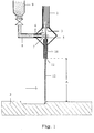
- FIG. 1 shows that part of a high-pressure water jet machining device which faces the workpiece to be machined.
- the device comprises a steel supply line 1, which is closed at the bottom, in the direction of a quartz glass workpiece 2, by a water nozzle 3.
- a compressed water jet 5 flows from the feed line 1 into the mixing chamber 4 via the water nozzle 3.
- the mixing chamber 4 is supplied with an abrasive 7 in the form of finely divided garnet or silicon carbide through a side inlet 6.
- the inlet 6 is connected via a flexible hose 8 to a reservoir 9 for the abrasive 7.
- the abrasive 7 introduced into the mixing chamber 4 is entrained by the water jet 5 and fed to a focusing tube 10 which is attached to the lower end of the mixing chamber 4.
- the water jet 12 loaded with abrasive agent 7 emerges from a focus nozzle 11 at high speed and thereby hits the surface of the workpiece 2.
- the workpiece 2 is held by means of a workpiece holder (not shown in the figure) held.
- the focusing tube 10 together with the mixing chamber 4 can be displaced in the direction of the water jet 12 and by means of an xy feed unit in the directions perpendicular thereto, as indicated by the directional arrow.
- the xy feed unit is connected to a computer-controlled control unit.
- the working distance between the focus nozzle 11 and the surface of the workpiece 2 to be machined is designated "A" in FIG.
- the working pressure within the supply line1 is set to a value of 100 MPa.
- the water nozzle 3 has an inner diameter of 0.3 mm.
- the water jet 5 is mixed within the mixing chamber 4 finely divided and sharp-edged SiC particles 7 with an average grain size of 135 microns, a density of 3.2 g / cm 3 and a hardness of 2700 Hv.
- the mass flow of the SiC particles fed to the mixing chamber is set to 30 cm 3 / min, ie about 100 g / min.
- the length of the focusing tube 10 is 35 mm, the diameter of the focus nozzle 11 corresponds to 1.2 mm half the width of the groove to be milled.
- the working distance A is kept constant at a value of 5 mm.
- the diameter of the Ring grooves 13 to be milled are entered into the control unit, so that by means of the xy feed unit the focusing tube 10 in corresponding circular movements over the Workpiece top 14 is moved.
- the focusing tube 10 moves across the width of the milling ring groove 13 radially from the inside out and back again, being full after each Rotation of the workpiece 14, the focusing tube 10 radially offset by a distance of 1.2 mm becomes. There are therefore two parallel and adjacent milling cuts for production each ring groove 13 required.
- the corresponding processing of the quartz glass workpiece 2 while setting the above Parameter in the high pressure water jet processing device shown in Figure 1 is finished within minutes.
- the milled ring grooves 13 are sharp-edged and are characterized by vertical side walls.
- the narrow 1.5 mm wide webs 15 between neighboring ring grooves are even and undamaged; there were no flaking cracks still found in the quartz glass workpiece 2.
- a disk-shaped workpiece 2 made of quartz glass with an outside diameter of 200 mm should be an annular, outer circumferential step 16 with a width "B" of 30 mm and a height "H” of 100 mm are generated by milling.
- the step edge 17 should be sharp be.
- the working pressure within supply line 1 is set to a value of 50 MPa.
- the water nozzle 3 has an inner diameter of 0.2 mm.
- the water jet 5 will within the mixing chamber 4 finely divided garnet particles 7 with an average grain size corresponding to 100 mesh (corresponds to an average diameter of approximately 150 ⁇ m).
- the mass flow of the garnet particles fed to the mixing chamber becomes approximately 130 g / min set.
- the focusing tube 10 is 35 mm long, the diameter of the focus nozzle 11 is 1.2 mm.
- the working distance A is kept constant at a value of 3 mm.
- the geometric dimensions of the step to be milled are entered, so that by means of the xy feed unit, the focusing tube 10 from the outer surface 18 of the Workpiece 2 starting in circular, inward narrowing movements over the top 14 of the workpiece 2 is moved.
- the feed speed is thereby set to 500 mm / min.
- a plate-shaped workpiece 2 made of quartz glass four should be parallel, at a distance of 5 mm mutually extending, 15 mm deep and 5 mm wide V-grooves 19 are milled.
- the upper boundary lines 20 of the V-grooves 19 should be rounded and diffuse.
- the working pressure within supply line 1 is set to a value of 20 MPa.
- the water nozzle 3 has an inner diameter of 0.4 mm.
- the water jet 5 is mixed within the mixing chamber 4 finely divided and sharp-edged SiC particles 7 with an average grain size of 135 microns, a density of 3.2 g / cm 3 and a hardness of 2700 Hv.
- the mass flow of the SiC particles fed to the mixing chamber is set to 40 cm 3 / min, ie about 130 g / min.
- the length of the focusing tube 10 is 35 mm, the diameter of the focus nozzle 11 is 2.0 mm.
- the working distance A is kept constant at a value of 20 mm. Length and distance of the V-grooves 19 to be milled are entered into the control unit, so that by means of the xy feed unit the focusing tube 10 in parallel longitudinal movements over the top of the workpiece 14 is moved.
- the feed speed is 6000 mm / min set.
- the exemplary embodiments described above serve to explain basic working methods when processing quartz glass components using an abrasive water jet. They give clues for specific machining tasks, for example milling out a rotating one Flange of a quartz glass bell or a milling of V-grooves to insert Sealing rings.
Landscapes
- Engineering & Computer Science (AREA)
- Mechanical Engineering (AREA)
- Chemical & Material Sciences (AREA)
- Geochemistry & Mineralogy (AREA)
- Chemical Kinetics & Catalysis (AREA)
- General Chemical & Material Sciences (AREA)
- Life Sciences & Earth Sciences (AREA)
- Materials Engineering (AREA)
- Organic Chemistry (AREA)
- Perforating, Stamping-Out Or Severing By Means Other Than Cutting (AREA)
- Processing Of Stones Or Stones Resemblance Materials (AREA)
- Surface Treatment Of Glass (AREA)
- Re-Forming, After-Treatment, Cutting And Transporting Of Glass Products (AREA)
Applications Claiming Priority (2)
| Application Number | Priority Date | Filing Date | Title |
|---|---|---|---|
| US104435 | 1979-12-17 | ||
| US10443598A | 1998-06-25 | 1998-06-25 |
Publications (2)
| Publication Number | Publication Date |
|---|---|
| EP0967183A1 true EP0967183A1 (fr) | 1999-12-29 |
| EP0967183B1 EP0967183B1 (fr) | 2004-04-07 |
Family
ID=22300461
Family Applications (1)
| Application Number | Title | Priority Date | Filing Date |
|---|---|---|---|
| EP99110700A Expired - Lifetime EP0967183B1 (fr) | 1998-06-25 | 1999-06-02 | Procédé de traitement d'un élément en verre de quartz |
Country Status (5)
| Country | Link |
|---|---|
| EP (1) | EP0967183B1 (fr) |
| JP (1) | JP2000024926A (fr) |
| KR (1) | KR100569739B1 (fr) |
| DE (1) | DE59909085D1 (fr) |
| TW (1) | TWI225472B (fr) |
Cited By (2)
| Publication number | Priority date | Publication date | Assignee | Title |
|---|---|---|---|---|
| EP1123777A1 (fr) * | 2000-02-10 | 2001-08-16 | ETAT-FRANCAIS représenté par le Délégué Général pour l' Armement | Dispositif de neutralisation d'engins explosifs par jet d'eau basse pression |
| EP4384362A2 (fr) * | 2021-08-12 | 2024-06-19 | Owens-Brockway Glass Container Inc. | Production de trous dans des récipients en verre |
Families Citing this family (2)
| Publication number | Priority date | Publication date | Assignee | Title |
|---|---|---|---|---|
| KR101145904B1 (ko) * | 2008-10-02 | 2012-05-15 | 이유진 | 워터젯 커팅기를 이용한 글라스 커팅방법 |
| CN102380829B (zh) * | 2010-08-31 | 2015-11-18 | 鸿富锦精密工业(深圳)有限公司 | 喷砂装置及形成图案的方法 |
Citations (2)
| Publication number | Priority date | Publication date | Assignee | Title |
|---|---|---|---|---|
| EP0385484A1 (fr) * | 1989-03-02 | 1990-09-05 | Osvetlovaci Sklo, Statni Podnik | Procédé pour rendre mats des objects en verre, en particulier dans un but d'éclairage |
| EP0704891A1 (fr) * | 1994-09-30 | 1996-04-03 | Shin-Etsu Handotai Company Limited | Gabarit en verre de quartz pour le traitement thermique de plaquettes semi-conductrices et procédé de fabrication |
Family Cites Families (1)
| Publication number | Priority date | Publication date | Assignee | Title |
|---|---|---|---|---|
| NL1007589C1 (nl) * | 1997-11-20 | 1999-05-25 | Tno | Werkwijze en inrichting voor het bewerken van een werkstuk. |
-
1999
- 1999-06-02 DE DE59909085T patent/DE59909085D1/de not_active Expired - Fee Related
- 1999-06-02 EP EP99110700A patent/EP0967183B1/fr not_active Expired - Lifetime
- 1999-06-04 TW TW088109315A patent/TWI225472B/zh not_active IP Right Cessation
- 1999-06-16 KR KR1019990022479A patent/KR100569739B1/ko not_active Expired - Fee Related
- 1999-06-25 JP JP11180266A patent/JP2000024926A/ja active Pending
Patent Citations (2)
| Publication number | Priority date | Publication date | Assignee | Title |
|---|---|---|---|---|
| EP0385484A1 (fr) * | 1989-03-02 | 1990-09-05 | Osvetlovaci Sklo, Statni Podnik | Procédé pour rendre mats des objects en verre, en particulier dans un but d'éclairage |
| EP0704891A1 (fr) * | 1994-09-30 | 1996-04-03 | Shin-Etsu Handotai Company Limited | Gabarit en verre de quartz pour le traitement thermique de plaquettes semi-conductrices et procédé de fabrication |
Cited By (3)
| Publication number | Priority date | Publication date | Assignee | Title |
|---|---|---|---|---|
| EP1123777A1 (fr) * | 2000-02-10 | 2001-08-16 | ETAT-FRANCAIS représenté par le Délégué Général pour l' Armement | Dispositif de neutralisation d'engins explosifs par jet d'eau basse pression |
| FR2804895A1 (fr) * | 2000-02-10 | 2001-08-17 | France Etat | Dispositif de neutralisation d'engins explosifs par jet d'eau basse pression |
| EP4384362A2 (fr) * | 2021-08-12 | 2024-06-19 | Owens-Brockway Glass Container Inc. | Production de trous dans des récipients en verre |
Also Published As
| Publication number | Publication date |
|---|---|
| KR100569739B1 (ko) | 2006-04-11 |
| TWI225472B (en) | 2004-12-21 |
| DE59909085D1 (de) | 2004-05-13 |
| EP0967183B1 (fr) | 2004-04-07 |
| JP2000024926A (ja) | 2000-01-25 |
| KR20000006210A (ko) | 2000-01-25 |
Similar Documents
| Publication | Publication Date | Title |
|---|---|---|
| DE69630832T2 (de) | Verfahren zur Herstellung von diamantbeschichteten Schneideinsätzen | |
| DE69823960T2 (de) | Verfahren zur Herstellung eines Löcherrasiersystems | |
| EP0565742A1 (fr) | Procédé pour le finissage de surfaces de pièces | |
| EP3670041A1 (fr) | Procédé de fabrication d'un segment de traitement pour le traitement à sec de matériaux de béton | |
| DE3045760A1 (de) | Verfahren zum planschleifen von flachen platten u.dgl. | |
| EP3670036A1 (fr) | Procédé de fabrication d'un segment de traitement pour le traitement à sec de matériaux de béton | |
| DE4229781A1 (de) | Verfahren zum bohren eines loches in ein hartes, jedoch bruechiges material und vorrichtung hierfuer | |
| EP3670035A1 (fr) | Procédé de fabrication d'un segment de traitement destiné au forage à sec de matériaux de béton | |
| EP3670038A1 (fr) | Procédé de fabrication d'un segment de traitement pour le traitement à sec de matériaux de béton | |
| EP0909611A1 (fr) | Procédé pour meuler les surfaces de pièces et dispositif pour la mise en oeuvre du procédé | |
| EP2682219A1 (fr) | Procédé d'usinage d'une pièce | |
| EP3670040A1 (fr) | Procédé de fabrication d'un segment de traitement pour le traitement à sec de matériaux de béton | |
| DE3415332A1 (de) | Verfahren zum herstellen eines raeumwerkzeugs | |
| EP0967183B1 (fr) | Procédé de traitement d'un élément en verre de quartz | |
| DE202020004003U1 (de) | Werkzeugmaschine zur Laserkonditionierung von Schleifwerkzeugen unabhängig von deren Spezifikation | |
| DE3218953C2 (de) | Verfahren und Vorrichtung zur Ausbildung einer Schrägrille in einer Halbleitervorrichtung | |
| WO2011006479A1 (fr) | Outil et procédé de fabrication d'un outil | |
| DE102018114139A1 (de) | Tieflochbohrer und Bohrwerkzeug mit einer oder mehreren Mulden in der Spanfläche | |
| EP3609650B1 (fr) | Dispositif et procédé pour la rugosification des surfaces de contact de cylindres | |
| EP0555285A1 (fr) | Procede pour l'usinage des surfaces interieures d'alesages. | |
| WO2023222822A1 (fr) | Procédé de production d'un outil de coupe | |
| DE102014018541B4 (de) | Verfahren zur Finishbearbeitung von Werkstückoberflächen | |
| EP0494305A1 (fr) | Procede de traitement abrasif d'articles | |
| EP2046510B1 (fr) | Lance de pulvérisation | |
| DE4224139C2 (de) | Verfahren und Werkzeug zum Feinschleifen oder Honen einer kugelförmig gekrümmten Stirnfläche an einem Werkstückschaft |
Legal Events
| Date | Code | Title | Description |
|---|---|---|---|
| PUAI | Public reference made under article 153(3) epc to a published international application that has entered the european phase |
Free format text: ORIGINAL CODE: 0009012 |
|
| 17P | Request for examination filed |
Effective date: 19990623 |
|
| AK | Designated contracting states |
Kind code of ref document: A1 Designated state(s): DE FR GB NL |
|
| AX | Request for extension of the european patent |
Free format text: AL;LT;LV;MK;RO;SI |
|
| AKX | Designation fees paid |
Free format text: DE FR GB NL |
|
| 17Q | First examination report despatched |
Effective date: 20010516 |
|
| GRAP | Despatch of communication of intention to grant a patent |
Free format text: ORIGINAL CODE: EPIDOSNIGR1 |
|
| GRAS | Grant fee paid |
Free format text: ORIGINAL CODE: EPIDOSNIGR3 |
|
| GRAA | (expected) grant |
Free format text: ORIGINAL CODE: 0009210 |
|
| AK | Designated contracting states |
Kind code of ref document: B1 Designated state(s): DE FR GB NL |
|
| PG25 | Lapsed in a contracting state [announced via postgrant information from national office to epo] |
Ref country code: NL Free format text: LAPSE BECAUSE OF FAILURE TO SUBMIT A TRANSLATION OF THE DESCRIPTION OR TO PAY THE FEE WITHIN THE PRESCRIBED TIME-LIMIT Effective date: 20040407 Ref country code: GB Free format text: LAPSE BECAUSE OF FAILURE TO SUBMIT A TRANSLATION OF THE DESCRIPTION OR TO PAY THE FEE WITHIN THE PRESCRIBED TIME-LIMIT Effective date: 20040407 Ref country code: FR Free format text: LAPSE BECAUSE OF FAILURE TO SUBMIT A TRANSLATION OF THE DESCRIPTION OR TO PAY THE FEE WITHIN THE PRESCRIBED TIME-LIMIT Effective date: 20040407 |
|
| REG | Reference to a national code |
Ref country code: GB Ref legal event code: FG4D Free format text: NOT ENGLISH |
|
| REF | Corresponds to: |
Ref document number: 59909085 Country of ref document: DE Date of ref document: 20040513 Kind code of ref document: P |
|
| NLV1 | Nl: lapsed or annulled due to failure to fulfill the requirements of art. 29p and 29m of the patents act | ||
| GBV | Gb: ep patent (uk) treated as always having been void in accordance with gb section 77(7)/1977 [no translation filed] |
Effective date: 20040407 |
|
| PLBE | No opposition filed within time limit |
Free format text: ORIGINAL CODE: 0009261 |
|
| STAA | Information on the status of an ep patent application or granted ep patent |
Free format text: STATUS: NO OPPOSITION FILED WITHIN TIME LIMIT |
|
| EN | Fr: translation not filed | ||
| 26N | No opposition filed |
Effective date: 20050110 |
|
| PGFP | Annual fee paid to national office [announced via postgrant information from national office to epo] |
Ref country code: DE Payment date: 20050613 Year of fee payment: 7 |
|
| PG25 | Lapsed in a contracting state [announced via postgrant information from national office to epo] |
Ref country code: DE Free format text: LAPSE BECAUSE OF NON-PAYMENT OF DUE FEES Effective date: 20070103 |