EP0967334A1 - Membrane d'étanchéité pour obtenir une couche étanche aux liquides dans le sol - Google Patents
Membrane d'étanchéité pour obtenir une couche étanche aux liquides dans le sol Download PDFInfo
- Publication number
- EP0967334A1 EP0967334A1 EP99111720A EP99111720A EP0967334A1 EP 0967334 A1 EP0967334 A1 EP 0967334A1 EP 99111720 A EP99111720 A EP 99111720A EP 99111720 A EP99111720 A EP 99111720A EP 0967334 A1 EP0967334 A1 EP 0967334A1
- Authority
- EP
- European Patent Office
- Prior art keywords
- layer
- sealing mat
- sealing
- water
- paper
- Prior art date
- Legal status (The legal status is an assumption and is not a legal conclusion. Google has not performed a legal analysis and makes no representation as to the accuracy of the status listed.)
- Granted
Links
- 238000007789 sealing Methods 0.000 title claims description 67
- 239000002689 soil Substances 0.000 title claims description 3
- 229910000278 bentonite Inorganic materials 0.000 claims abstract description 33
- 239000000440 bentonite Substances 0.000 claims abstract description 33
- SVPXDRXYRYOSEX-UHFFFAOYSA-N bentoquatam Chemical group O.O=[Si]=O.O=[Al]O[Al]=O SVPXDRXYRYOSEX-UHFFFAOYSA-N 0.000 claims abstract description 33
- XLYOFNOQVPJJNP-UHFFFAOYSA-N water Substances O XLYOFNOQVPJJNP-UHFFFAOYSA-N 0.000 claims abstract description 28
- 229910052500 inorganic mineral Inorganic materials 0.000 claims abstract description 3
- 239000011707 mineral Substances 0.000 claims abstract description 3
- 239000003566 sealing material Substances 0.000 claims description 16
- 238000010521 absorption reaction Methods 0.000 claims description 5
- 238000010276 construction Methods 0.000 abstract description 4
- 239000000565 sealant Substances 0.000 abstract description 4
- 238000004078 waterproofing Methods 0.000 abstract 1
- 235000012216 bentonite Nutrition 0.000 description 33
- 239000000123 paper Substances 0.000 description 20
- 230000008961 swelling Effects 0.000 description 11
- 238000004519 manufacturing process Methods 0.000 description 7
- 239000004927 clay Substances 0.000 description 6
- 239000002245 particle Substances 0.000 description 5
- 238000000034 method Methods 0.000 description 4
- VYPSYNLAJGMNEJ-UHFFFAOYSA-N Silicium dioxide Chemical compound O=[Si]=O VYPSYNLAJGMNEJ-UHFFFAOYSA-N 0.000 description 3
- 235000013312 flour Nutrition 0.000 description 3
- 238000009434 installation Methods 0.000 description 3
- 239000000463 material Substances 0.000 description 3
- 239000011148 porous material Substances 0.000 description 3
- 238000001035 drying Methods 0.000 description 2
- 239000003292 glue Substances 0.000 description 2
- 239000004576 sand Substances 0.000 description 2
- 239000000126 substance Substances 0.000 description 2
- 229910021532 Calcite Inorganic materials 0.000 description 1
- 241001122767 Theaceae Species 0.000 description 1
- 238000004026 adhesive bonding Methods 0.000 description 1
- TZCXTZWJZNENPQ-UHFFFAOYSA-L barium sulfate Chemical compound [Ba+2].[O-]S([O-])(=O)=O TZCXTZWJZNENPQ-UHFFFAOYSA-L 0.000 description 1
- 239000010428 baryte Substances 0.000 description 1
- 229910052601 baryte Inorganic materials 0.000 description 1
- 238000009412 basement excavation Methods 0.000 description 1
- 230000015572 biosynthetic process Effects 0.000 description 1
- 230000001419 dependent effect Effects 0.000 description 1
- 238000011161 development Methods 0.000 description 1
- 230000018109 developmental process Effects 0.000 description 1
- GUJOJGAPFQRJSV-UHFFFAOYSA-N dialuminum;dioxosilane;oxygen(2-);hydrate Chemical compound O.[O-2].[O-2].[O-2].[Al+3].[Al+3].O=[Si]=O.O=[Si]=O.O=[Si]=O.O=[Si]=O GUJOJGAPFQRJSV-UHFFFAOYSA-N 0.000 description 1
- 238000006073 displacement reaction Methods 0.000 description 1
- 238000004090 dissolution Methods 0.000 description 1
- 238000010410 dusting Methods 0.000 description 1
- 230000003628 erosive effect Effects 0.000 description 1
- 239000010433 feldspar Substances 0.000 description 1
- 239000011491 glass wool Substances 0.000 description 1
- 229910052900 illite Inorganic materials 0.000 description 1
- 239000007788 liquid Substances 0.000 description 1
- 239000000203 mixture Substances 0.000 description 1
- 229910052901 montmorillonite Inorganic materials 0.000 description 1
- 239000005445 natural material Substances 0.000 description 1
- VGIBGUSAECPPNB-UHFFFAOYSA-L nonaaluminum;magnesium;tripotassium;1,3-dioxido-2,4,5-trioxa-1,3-disilabicyclo[1.1.1]pentane;iron(2+);oxygen(2-);fluoride;hydroxide Chemical compound [OH-].[O-2].[O-2].[O-2].[O-2].[O-2].[F-].[Mg+2].[Al+3].[Al+3].[Al+3].[Al+3].[Al+3].[Al+3].[Al+3].[Al+3].[Al+3].[K+].[K+].[K+].[Fe+2].O1[Si]2([O-])O[Si]1([O-])O2.O1[Si]2([O-])O[Si]1([O-])O2.O1[Si]2([O-])O[Si]1([O-])O2.O1[Si]2([O-])O[Si]1([O-])O2.O1[Si]2([O-])O[Si]1([O-])O2.O1[Si]2([O-])O[Si]1([O-])O2.O1[Si]2([O-])O[Si]1([O-])O2 VGIBGUSAECPPNB-UHFFFAOYSA-L 0.000 description 1
- 238000005192 partition Methods 0.000 description 1
- 230000035699 permeability Effects 0.000 description 1
- 239000004033 plastic Substances 0.000 description 1
- 229920003023 plastic Polymers 0.000 description 1
- 239000002985 plastic film Substances 0.000 description 1
- 229920006255 plastic film Polymers 0.000 description 1
- 239000000843 powder Substances 0.000 description 1
- 238000003825 pressing Methods 0.000 description 1
- 229910021647 smectite Inorganic materials 0.000 description 1
- 238000003860 storage Methods 0.000 description 1
- 239000012209 synthetic fiber Substances 0.000 description 1
- 229920002994 synthetic fiber Polymers 0.000 description 1
- 238000003466 welding Methods 0.000 description 1
Images
Classifications
-
- E—FIXED CONSTRUCTIONS
- E02—HYDRAULIC ENGINEERING; FOUNDATIONS; SOIL SHIFTING
- E02D—FOUNDATIONS; EXCAVATIONS; EMBANKMENTS; UNDERGROUND OR UNDERWATER STRUCTURES
- E02D31/00—Protective arrangements for foundations or foundation structures; Ground foundation measures for protecting the soil or the subsoil water, e.g. preventing or counteracting oil pollution
- E02D31/002—Ground foundation measures for protecting the soil or subsoil water, e.g. preventing or counteracting oil pollution
- E02D31/004—Sealing liners
-
- E—FIXED CONSTRUCTIONS
- E02—HYDRAULIC ENGINEERING; FOUNDATIONS; SOIL SHIFTING
- E02D—FOUNDATIONS; EXCAVATIONS; EMBANKMENTS; UNDERGROUND OR UNDERWATER STRUCTURES
- E02D2300/00—Materials
- E02D2300/0037—Clays
- E02D2300/004—Bentonite or bentonite-like
Definitions
- Liquid-tight layers to form a seal in the ground are used in different ways Areas used, such as in landfill construction, in the creation of biotopes, pond and Water systems and when connecting structures in the water area. Especially at small areas to be sealed, such as when creating small biotopes, pond or Water systems, however, each of the known sealing methods has disadvantages.
- the typical layer structure using such liquid-tight layers is first explained using the installation of a landfill or a large water system. After the excavation The bottom and embankments of the basin to be sealed are compacted. On it swellable, mineral sealing material applied. Clay-like substances are suitable for this such as clay flour, clay sealants and the like. This also includes the material group Bentonites, of which various types are extremely suitable for this purpose different swelling and water absorption properties are on the market and the following representative of the clay flours that can be used for sealing purposes, predominantly cover is taken.
- the applied bentonite layer - usually about 1 to 2 cm thick - is with a covering layer at least 20 to 30 cm thick to form a load that counteracts the swelling pressure generated by the swelling bentonite when water is supplied.
- the sealing mat is very good can be rolled up and thus easily transported as a roll and in a simple manner Unwinding to be relocated.
- the higher water permeability of the second layer compared to the first layer can be achieved in that the paper of the second layer is more porous than the paper of the first Layer, i.e. that it has larger or more pores than that of the first layer.
- the second layer which is usually on top, is exposed to water more quickly dissolves as the first, usually bottom layer. This intensifies after the start of Dissolution of the paper the fact that it is easier to access water from above than from below. It also ensures that bentonite particles from the underside of the bentonite layer cannot migrate down too early due to the swelling process.
- the sealing mat selected from the many different materials for the sealing mat is such a bentonite which has a water absorption capacity of between 200 and 800%, and if this bentonite is arranged in the sealing mat with a basis weight of between 8 and 15 kg / m 2 , only one is sufficient Sealing mat for sealing against liquid leakage. If instead other sealing materials with a lower water absorption capacity and / or a lower mass density per area, ie a lower basis weight, are used, two or more sealing mats must be arranged one above the other in order to achieve a tight layer. Of course, this then increases the number of work steps required to achieve a seal, but is in principle possible.
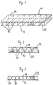
- Fig. 1 the sealing mat cut parallel to the longitudinal axis is shown in perspective, which is designated in its entirety by reference number 10.
- a first layer 12 which is arranged below, and a second, here above the first layer, essentially parallel to it, there are a plurality of side walls 16.
- These side walls 16 are essentially perpendicular to the layers 12, 14 and are at their upper and lower ends connected to the lower layer 12 and the upper layer 14, respectively.
- This connection can be made, for example, by needling or by means of an ecological glue.
- tubular chambers 22 are formed which are filled with sealing material 20. Because of its good swelling and thus sealing properties, bentonite is preferably used for this purpose, which is why bentonite is used as a sealing material in an exemplary but not restrictive manner.
- the side walls 16 run in the transverse direction of the sealing mat 10, i.e. so perpendicular to their longitudinal direction. They preferably have a distance of approximately 1.5 to 2.5 cm apart. This is advantageous in that the tubular chambers 22 located bentonite particles essentially only in the transverse direction the sealing mat 10, but not in the longitudinal direction. Because the side walls 16 have the aforementioned relatively small distance from one another, remains in the filled state the distance between the first layer 12 and the second layer 14 also largely constant. Consequently, the thickness of the sealing mat 10 and thus its tightness remains throughout Length practically constant. 1 is located with respect to the longitudinal direction the sealing mat 10 at the beginning and at the end of a side wall 16 which the sealing mat 10 completes in the longitudinal direction. As a result, the sealing mat also has the same at the ends Thickness up. However, the ends can also be formed so that the lower layer 12 and the protrude upper layer 14 over the last side wall 16 and connected together are.
- FIG. 2 differs from the first in that Side walls 17 are not perpendicular to the side walls 16 of the first embodiment lower layer 12 and the upper layer 14 are arranged, but that they chambers 23rd form with a U or V-shaped cross-section.
- the side walls 18 are tubular chambers 24 with an approximately round cross section.
- the chambers can also have other cross sections. It is important in any case that they prevent the unwanted displacement of the bentonite in the sealing mat.
- the side walls 16, 17 or 18 and the two layers 12, 14 are formed from paper.
- Paper as is known from the production of tea or coffee filters, has proven to be particularly suitable for the production of the second layer 14.
- a suitable grade has, for example, a basis weight of approximately 16.5 g / m 2 , a thickness of approximately 60 ⁇ m, a breaking strength in the dry state in the longitudinal and transverse directions of more than 13.0 N / 15 mm or more than 3, 2 N / 15 mm and a breaking force in the wet state in the transverse direction of more than 1.0 N / 15 mm and shows a sand loss of less than 75% with a particle size between 106 and 150 ⁇ m.
- papers for the production of serviettes or similar papers are also suitable for the second layer, provided they have specifications similar to those described above.
- the first layer 12 is made of less water-permeable paper, which is more stable than the paper second layer 14 is formed.
- paper has been found to be suitable for this purpose of bakery silk or napkins, which is more stable and waterproof than that for them second layer of paper that can be used, these papers each having a higher breaking strength, however, have less sand loss than the aforementioned papers.
- the aforementioned Papers for the formation of the first and second layers as well as the side walls come off Water exposure - albeit at different speeds - slowly and biologically be dismantled. Therefore, they can be used ecologically without hesitation.
- the sealing material used namely clay powder, such as bentonite, or other clay sealants are naturally occurring and environmentally friendly.
- the bentonites preferably used for the production of the sealing mat according to the invention are generally known.
- a typical example of this type of sealing material consists of: montmorillonite approx. 88% (smectite, bentonite), quartz (SiO 2 ) approx. 4%, calcite approx. 3%, illite approx. 3%, barite approx. 1% , Feldspar about 1%.
- montmorillonite approx. 88% smectite, bentonite
- quartz (SiO 2 ) approx. 4% calcite approx. 3%
- illite approx. 3% illite approx. 3%
- barite approx. 1% illite approx. 3%
- Feldspar about 1%.
- other materials with different compositions can be used to produce the sealing mat according to the invention.
- the sealing mat according to the invention is manufactured becomes.
- the sidewalls 16, 17 or 18 are attached to the first layer 12.
- the second layer 14 is attached to the side walls 16, 17 or 18.
- the sealing mat is on one end of the chambers closed, for example by the protruding first Layer 12 and second layer 14 are connected to one another on this end face.
- the Chambers are now filled with the sealing material, after which they are closed on this end face in a similar manner to the other end face become.
- the above fastening and connection operations can be both by gluing using an ecological glue as well as by needling with a suitable that is, biodegradable thread.
- the now finished sealing mat can then be rolled up become.
- the rolled up one Sealing mat for transport, storage and sale in a dust-proof film, preferably transparent film, packed.
- the sealing mat according to the invention can then be simply in place by unwinding be interpreted. In contrast to the application of the Sealing material alone also accepted unevenness, for example smaller stones become.
- Another advantage of this sealing mat compared to the needled mentioned above Sealing mats are that they are more supple due to the lower layer of paper is and adapts more easily to unevenness in the terrain, especially in the slope area Slipping prevented.
- the subsurface should in any case be well compacted in order to subsequent application of a load no more than necessary to discard and the tightness of the Affect layer.
- the spatial configuration of the sealing mat is not based on the exemplary embodiments specified above limited.
- the tubular chambers 22, 23 and 24 can pass through an additional, extending in the longitudinal direction of the sealing mat partition.
- these tubular chambers are already after the application of second layer only open at one end, over which they are sealed can be filled.
- Sealing material prevented even more from slipping.
- the chambers can also be in Longitudinal direction of the sealing mat instead of running in the transverse direction, which is why such a designed sealing mat can be laid out on longer slopes parallel to the slope and does not have to be installed perpendicular to it. Therefore it must - especially with not too high embankments - not so often cut and overlapped.
- the sealing mat according to the invention can also be used, for example, for green roofs and house wall drying or drying. It can also be advantageous the less water permeable first layer on top and the more water permeable Arrange layer below if access to water from below and not as in the previous ones Examples from above can be expected and the swelling process should begin below.
Landscapes
- Engineering & Computer Science (AREA)
- Environmental & Geological Engineering (AREA)
- Life Sciences & Earth Sciences (AREA)
- Hydrology & Water Resources (AREA)
- General Life Sciences & Earth Sciences (AREA)
- Mining & Mineral Resources (AREA)
- Paleontology (AREA)
- Civil Engineering (AREA)
- General Engineering & Computer Science (AREA)
- Structural Engineering (AREA)
- Revetment (AREA)
- Laminated Bodies (AREA)
- Investigation Of Foundation Soil And Reinforcement Of Foundation Soil By Compacting Or Drainage (AREA)
- Processing Of Solid Wastes (AREA)
Applications Claiming Priority (2)
| Application Number | Priority Date | Filing Date | Title |
|---|---|---|---|
| DE19827909A DE19827909A1 (de) | 1998-06-23 | 1998-06-23 | Dichtmatte zur Herstellung einer flüssigkeitsdichten Schicht im Erdreich |
| DE19827909 | 1998-06-23 |
Publications (2)
| Publication Number | Publication Date |
|---|---|
| EP0967334A1 true EP0967334A1 (fr) | 1999-12-29 |
| EP0967334B1 EP0967334B1 (fr) | 2003-08-13 |
Family
ID=7871731
Family Applications (1)
| Application Number | Title | Priority Date | Filing Date |
|---|---|---|---|
| EP99111720A Expired - Lifetime EP0967334B1 (fr) | 1998-06-23 | 1999-06-17 | Membrane d'étanchéité pour obtenir une couche étanche aux liquides dans le sol |
Country Status (3)
| Country | Link |
|---|---|
| EP (1) | EP0967334B1 (fr) |
| AT (1) | ATE247196T1 (fr) |
| DE (2) | DE19827909A1 (fr) |
Cited By (1)
| Publication number | Priority date | Publication date | Assignee | Title |
|---|---|---|---|---|
| EP1416094A1 (fr) * | 2002-10-10 | 2004-05-06 | Cidieffe S.r.l. | Geomembrane |
Citations (3)
| Publication number | Priority date | Publication date | Assignee | Title |
|---|---|---|---|---|
| US4467015A (en) * | 1981-11-02 | 1984-08-21 | Clem Arthur G | Waterproofing structure |
| US4565468A (en) * | 1983-10-24 | 1986-01-21 | Crawford Leslie A | Moisture impervient barrier and method for making same |
| EP0442597A1 (fr) * | 1990-02-15 | 1991-08-21 | American Colloid Company | Panneau imperméable à l'humidité capable d'hydratation rapide/retardée |
Family Cites Families (4)
| Publication number | Priority date | Publication date | Assignee | Title |
|---|---|---|---|---|
| EP0362193B1 (fr) * | 1988-09-28 | 1992-12-02 | Girmes Gmbh | Procédé pour l'étanchement à la pénétration de liquide et/ou de gaz |
| DE4012301C2 (de) * | 1990-04-18 | 1999-03-25 | Huesker Synthetic Gmbh & Co | Schalungshülle |
| DE4203861A1 (de) * | 1992-02-11 | 1993-08-12 | Naue Fasertechnik | Wasser- und/oder oelundurchlaessige dichtungsmatte aus quellfaehigem ton |
| DE4243254A1 (de) * | 1992-04-02 | 1993-10-07 | Naue Fasertechnik | Verfahren zur Herstellung einer wasser- und/oder ölundurchlässigen quellfähigen Ton enthaltenden Dichtungsmatte |
-
1998
- 1998-06-23 DE DE19827909A patent/DE19827909A1/de not_active Withdrawn
-
1999
- 1999-06-17 DE DE59906564T patent/DE59906564D1/de not_active Expired - Lifetime
- 1999-06-17 AT AT99111720T patent/ATE247196T1/de not_active IP Right Cessation
- 1999-06-17 EP EP99111720A patent/EP0967334B1/fr not_active Expired - Lifetime
Patent Citations (3)
| Publication number | Priority date | Publication date | Assignee | Title |
|---|---|---|---|---|
| US4467015A (en) * | 1981-11-02 | 1984-08-21 | Clem Arthur G | Waterproofing structure |
| US4565468A (en) * | 1983-10-24 | 1986-01-21 | Crawford Leslie A | Moisture impervient barrier and method for making same |
| EP0442597A1 (fr) * | 1990-02-15 | 1991-08-21 | American Colloid Company | Panneau imperméable à l'humidité capable d'hydratation rapide/retardée |
Cited By (1)
| Publication number | Priority date | Publication date | Assignee | Title |
|---|---|---|---|---|
| EP1416094A1 (fr) * | 2002-10-10 | 2004-05-06 | Cidieffe S.r.l. | Geomembrane |
Also Published As
| Publication number | Publication date |
|---|---|
| DE19827909A1 (de) | 1999-12-30 |
| EP0967334B1 (fr) | 2003-08-13 |
| DE59906564D1 (de) | 2003-09-18 |
| ATE247196T1 (de) | 2003-08-15 |
Similar Documents
| Publication | Publication Date | Title |
|---|---|---|
| DE69009416T2 (de) | Verbesserte Systeme für Flüssigkeitsleitungen. | |
| DE2327618A1 (de) | Grossflaechiges mehrschichten-draenageelement | |
| DE2657964A1 (de) | Wasserdichter fussboden- bzw. wandbelag insbesondere fuer terrassen, behaelter u.dgl. und verfahren zu seiner herstellung | |
| DE102008026567B4 (de) | Hochwasserschutzvorrichtung, -wand und Verfahren zu deren Herstellung | |
| EP0684343B1 (fr) | Procédé pour la fabrication de parois étanches | |
| DE202016102923U1 (de) | Pflanzflächenaufbau | |
| EP0967334B1 (fr) | Membrane d'étanchéité pour obtenir une couche étanche aux liquides dans le sol | |
| DE19716516A1 (de) | Dämm-Dränelemente aus Kunststoffhartschaum und Verfahren für die Anwendung im Erdreich | |
| DE69815344T2 (de) | Artikel zur abdichtung für den gebrauch an gebäuden | |
| DE2415023B2 (de) | Laermschutzwall | |
| DE4012301C2 (de) | Schalungshülle | |
| DE19649628A1 (de) | Mineralischer Dichtungsaufbau, insbesondere für Oberflächendichtungen von Deponien, Altlastflächen, Industriebrachen und dergleichen | |
| DE69101982T2 (de) | Feuchtdichte Platte fähig zur schnellen/verzögerten Hydratation. | |
| DE2102763C3 (de) | Filterschicht, insbesondere für ein Drainagerohr | |
| DE202022103585U1 (de) | Biologisch abbaubare Bodendichtungsbahn | |
| DE4131743C2 (de) | Basisabdichtung für Mülldeponien | |
| DE69821254T2 (de) | Stabilisiertes gefüge, insbesondere vom typ ballast, und verfahren zur stabilisierung eines solchen gefüges | |
| DE9212955U1 (de) | Dränage-Matte | |
| DE2433975A1 (de) | Bahnenmaterial fuer entwaesserungszwecke | |
| DE60203517T2 (de) | Mehrlagige Dichtungsmatte | |
| DE4417312A1 (de) | Schutzschicht für Deponie- und andere Abdichtungen | |
| CH678739A5 (en) | Bank-covering method for plant growth - comprises flat textile with cover impervious to material sprayed on | |
| DE2515362C3 (de) | Stützmauer aus Bauelementen | |
| DE4109050C2 (de) | Dränmatte mit Sperrwirkung | |
| AT369469B (de) | Entwaesserungselement |
Legal Events
| Date | Code | Title | Description |
|---|---|---|---|
| PUAI | Public reference made under article 153(3) epc to a published international application that has entered the european phase |
Free format text: ORIGINAL CODE: 0009012 |
|
| AK | Designated contracting states |
Kind code of ref document: A1 Designated state(s): AT BE CH DE ES FR GB IT LI |
|
| AX | Request for extension of the european patent |
Free format text: AL;LT;LV;MK;RO;SI |
|
| 17P | Request for examination filed |
Effective date: 20000629 |
|
| AKX | Designation fees paid |
Free format text: AT BE CH DE ES FR GB IT LI |
|
| 17Q | First examination report despatched |
Effective date: 20010222 |
|
| GRAH | Despatch of communication of intention to grant a patent |
Free format text: ORIGINAL CODE: EPIDOS IGRA |
|
| GRAH | Despatch of communication of intention to grant a patent |
Free format text: ORIGINAL CODE: EPIDOS IGRA |
|
| GRAA | (expected) grant |
Free format text: ORIGINAL CODE: 0009210 |
|
| AK | Designated contracting states |
Designated state(s): AT BE CH DE ES FR GB IT LI |
|
| PG25 | Lapsed in a contracting state [announced via postgrant information from national office to epo] |
Ref country code: IT Free format text: LAPSE BECAUSE OF FAILURE TO SUBMIT A TRANSLATION OF THE DESCRIPTION OR TO PAY THE FEE WITHIN THE PRE;WARNING: LAPSES OF ITALIAN PATENTS WITH EFFECTIVE DATE BEFORE 2007 MAY HAVE OCCURRED AT ANY TIME BEFORE 2007. THE CORRECT EFFECTIVE DATE MAY BE DIFFERENT FROM THE ONE RECORDED.SCRIBED TIME-LIMIT Effective date: 20030813 Ref country code: GB Free format text: LAPSE BECAUSE OF FAILURE TO SUBMIT A TRANSLATION OF THE DESCRIPTION OR TO PAY THE FEE WITHIN THE PRESCRIBED TIME-LIMIT Effective date: 20030813 Ref country code: FR Free format text: LAPSE BECAUSE OF NON-PAYMENT OF DUE FEES Effective date: 20030813 Ref country code: ES Free format text: LAPSE BECAUSE OF FAILURE TO SUBMIT A TRANSLATION OF THE DESCRIPTION OR TO PAY THE FEE WITHIN THE PRESCRIBED TIME-LIMIT Effective date: 20030813 |
|
| REG | Reference to a national code |
Ref country code: GB Ref legal event code: FG4D Free format text: NOT ENGLISH |
|
| REG | Reference to a national code |
Ref country code: CH Ref legal event code: EP |
|
| REF | Corresponds to: |
Ref document number: 59906564 Country of ref document: DE Date of ref document: 20030918 Kind code of ref document: P |
|
| GBV | Gb: ep patent (uk) treated as always having been void in accordance with gb section 77(7)/1977 [no translation filed] |
Effective date: 20030813 |
|
| PG25 | Lapsed in a contracting state [announced via postgrant information from national office to epo] |
Ref country code: AT Free format text: LAPSE BECAUSE OF NON-PAYMENT OF DUE FEES Effective date: 20040617 |
|
| PLBE | No opposition filed within time limit |
Free format text: ORIGINAL CODE: 0009261 |
|
| STAA | Information on the status of an ep patent application or granted ep patent |
Free format text: STATUS: NO OPPOSITION FILED WITHIN TIME LIMIT |
|
| PG25 | Lapsed in a contracting state [announced via postgrant information from national office to epo] |
Ref country code: LI Free format text: LAPSE BECAUSE OF NON-PAYMENT OF DUE FEES Effective date: 20040630 Ref country code: CH Free format text: LAPSE BECAUSE OF NON-PAYMENT OF DUE FEES Effective date: 20040630 Ref country code: BE Free format text: LAPSE BECAUSE OF NON-PAYMENT OF DUE FEES Effective date: 20040630 |
|
| 26N | No opposition filed |
Effective date: 20040514 |
|
| EN | Fr: translation not filed | ||
| BERE | Be: lapsed |
Owner name: *ZAUSER HANS Effective date: 20040630 |
|
| REG | Reference to a national code |
Ref country code: CH Ref legal event code: PL |
|
| PGFP | Annual fee paid to national office [announced via postgrant information from national office to epo] |
Ref country code: DE Payment date: 20140630 Year of fee payment: 16 |
|
| REG | Reference to a national code |
Ref country code: DE Ref legal event code: R119 Ref document number: 59906564 Country of ref document: DE |
|
| REG | Reference to a national code |
Ref country code: DE Ref legal event code: R119 Ref document number: 59906564 Country of ref document: DE Effective date: 20150101 |
|
| PG25 | Lapsed in a contracting state [announced via postgrant information from national office to epo] |
Ref country code: DE Free format text: LAPSE BECAUSE OF NON-PAYMENT OF DUE FEES Effective date: 20150101 |