EP0967370B1 - Brennkraftmaschine - Google Patents
Brennkraftmaschine Download PDFInfo
- Publication number
- EP0967370B1 EP0967370B1 EP99112276A EP99112276A EP0967370B1 EP 0967370 B1 EP0967370 B1 EP 0967370B1 EP 99112276 A EP99112276 A EP 99112276A EP 99112276 A EP99112276 A EP 99112276A EP 0967370 B1 EP0967370 B1 EP 0967370B1
- Authority
- EP
- European Patent Office
- Prior art keywords
- injector
- ignition plug
- cylinder
- internal combustion
- combustion engine
- Prior art date
- Legal status (The legal status is an assumption and is not a legal conclusion. Google has not performed a legal analysis and makes no representation as to the accuracy of the status listed.)
- Expired - Lifetime
Links
- 238000002485 combustion reaction Methods 0.000 title claims description 52
- 238000002347 injection Methods 0.000 claims description 68
- 239000007924 injection Substances 0.000 claims description 68
- 239000000446 fuel Substances 0.000 claims description 45
- XLYOFNOQVPJJNP-UHFFFAOYSA-N water Substances O XLYOFNOQVPJJNP-UHFFFAOYSA-N 0.000 claims description 9
- 238000006073 displacement reaction Methods 0.000 claims description 5
- 230000007246 mechanism Effects 0.000 claims description 3
- 239000007921 spray Substances 0.000 claims description 2
- 239000000203 mixture Substances 0.000 description 18
- 230000000694 effects Effects 0.000 description 4
- 239000000498 cooling water Substances 0.000 description 2
- 238000000034 method Methods 0.000 description 2
- OKTJSMMVPCPJKN-UHFFFAOYSA-N Carbon Chemical compound [C] OKTJSMMVPCPJKN-UHFFFAOYSA-N 0.000 description 1
- 229910052799 carbon Inorganic materials 0.000 description 1
- 238000001816 cooling Methods 0.000 description 1
- 230000001419 dependent effect Effects 0.000 description 1
- 238000000151 deposition Methods 0.000 description 1
Images






Classifications
-
- F—MECHANICAL ENGINEERING; LIGHTING; HEATING; WEAPONS; BLASTING
- F02—COMBUSTION ENGINES; HOT-GAS OR COMBUSTION-PRODUCT ENGINE PLANTS
- F02B—INTERNAL-COMBUSTION PISTON ENGINES; COMBUSTION ENGINES IN GENERAL
- F02B23/00—Other engines characterised by special shape or construction of combustion chambers to improve operation
- F02B23/08—Other engines characterised by special shape or construction of combustion chambers to improve operation with positive ignition
- F02B23/10—Other engines characterised by special shape or construction of combustion chambers to improve operation with positive ignition with separate admission of air and fuel into cylinder
- F02B23/101—Other engines characterised by special shape or construction of combustion chambers to improve operation with positive ignition with separate admission of air and fuel into cylinder the injector being placed on or close to the cylinder centre axis, e.g. with mixture formation using spray guided concepts
-
- F—MECHANICAL ENGINEERING; LIGHTING; HEATING; WEAPONS; BLASTING
- F02—COMBUSTION ENGINES; HOT-GAS OR COMBUSTION-PRODUCT ENGINE PLANTS
- F02F—CYLINDERS, PISTONS OR CASINGS, FOR COMBUSTION ENGINES; ARRANGEMENTS OF SEALINGS IN COMBUSTION ENGINES
- F02F1/00—Cylinders; Cylinder heads
- F02F1/24—Cylinder heads
- F02F1/242—Arrangement of spark plugs or injectors
-
- F—MECHANICAL ENGINEERING; LIGHTING; HEATING; WEAPONS; BLASTING
- F02—COMBUSTION ENGINES; HOT-GAS OR COMBUSTION-PRODUCT ENGINE PLANTS
- F02F—CYLINDERS, PISTONS OR CASINGS, FOR COMBUSTION ENGINES; ARRANGEMENTS OF SEALINGS IN COMBUSTION ENGINES
- F02F1/00—Cylinders; Cylinder heads
- F02F1/24—Cylinder heads
- F02F1/42—Shape or arrangement of intake or exhaust channels in cylinder heads
- F02F1/4214—Shape or arrangement of intake or exhaust channels in cylinder heads specially adapted for four or more valves per cylinder
- F02F1/4221—Shape or arrangement of intake or exhaust channels in cylinder heads specially adapted for four or more valves per cylinder particularly for three or more inlet valves
-
- F—MECHANICAL ENGINEERING; LIGHTING; HEATING; WEAPONS; BLASTING
- F02—COMBUSTION ENGINES; HOT-GAS OR COMBUSTION-PRODUCT ENGINE PLANTS
- F02B—INTERNAL-COMBUSTION PISTON ENGINES; COMBUSTION ENGINES IN GENERAL
- F02B23/00—Other engines characterised by special shape or construction of combustion chambers to improve operation
- F02B23/08—Other engines characterised by special shape or construction of combustion chambers to improve operation with positive ignition
- F02B2023/085—Other engines characterised by special shape or construction of combustion chambers to improve operation with positive ignition using several spark plugs per cylinder
-
- F—MECHANICAL ENGINEERING; LIGHTING; HEATING; WEAPONS; BLASTING
- F02—COMBUSTION ENGINES; HOT-GAS OR COMBUSTION-PRODUCT ENGINE PLANTS
- F02B—INTERNAL-COMBUSTION PISTON ENGINES; COMBUSTION ENGINES IN GENERAL
- F02B23/00—Other engines characterised by special shape or construction of combustion chambers to improve operation
- F02B23/08—Other engines characterised by special shape or construction of combustion chambers to improve operation with positive ignition
- F02B23/10—Other engines characterised by special shape or construction of combustion chambers to improve operation with positive ignition with separate admission of air and fuel into cylinder
- F02B2023/102—Other engines characterised by special shape or construction of combustion chambers to improve operation with positive ignition with separate admission of air and fuel into cylinder the spark plug being placed offset the cylinder centre axis
-
- F—MECHANICAL ENGINEERING; LIGHTING; HEATING; WEAPONS; BLASTING
- F02—COMBUSTION ENGINES; HOT-GAS OR COMBUSTION-PRODUCT ENGINE PLANTS
- F02B—INTERNAL-COMBUSTION PISTON ENGINES; COMBUSTION ENGINES IN GENERAL
- F02B75/00—Other engines
- F02B75/12—Other methods of operation
- F02B2075/125—Direct injection in the combustion chamber for spark ignition engines, i.e. not in pre-combustion chamber
-
- F—MECHANICAL ENGINEERING; LIGHTING; HEATING; WEAPONS; BLASTING
- F02—COMBUSTION ENGINES; HOT-GAS OR COMBUSTION-PRODUCT ENGINE PLANTS
- F02B—INTERNAL-COMBUSTION PISTON ENGINES; COMBUSTION ENGINES IN GENERAL
- F02B2275/00—Other engines, components or details, not provided for in other groups of this subclass
- F02B2275/18—DOHC [Double overhead camshaft]
-
- F—MECHANICAL ENGINEERING; LIGHTING; HEATING; WEAPONS; BLASTING
- F02—COMBUSTION ENGINES; HOT-GAS OR COMBUSTION-PRODUCT ENGINE PLANTS
- F02F—CYLINDERS, PISTONS OR CASINGS, FOR COMBUSTION ENGINES; ARRANGEMENTS OF SEALINGS IN COMBUSTION ENGINES
- F02F1/00—Cylinders; Cylinder heads
- F02F1/24—Cylinder heads
- F02F2001/244—Arrangement of valve stems in cylinder heads
- F02F2001/245—Arrangement of valve stems in cylinder heads the valve stems being orientated at an angle with the cylinder axis
-
- Y—GENERAL TAGGING OF NEW TECHNOLOGICAL DEVELOPMENTS; GENERAL TAGGING OF CROSS-SECTIONAL TECHNOLOGIES SPANNING OVER SEVERAL SECTIONS OF THE IPC; TECHNICAL SUBJECTS COVERED BY FORMER USPC CROSS-REFERENCE ART COLLECTIONS [XRACs] AND DIGESTS
- Y02—TECHNOLOGIES OR APPLICATIONS FOR MITIGATION OR ADAPTATION AGAINST CLIMATE CHANGE
- Y02T—CLIMATE CHANGE MITIGATION TECHNOLOGIES RELATED TO TRANSPORTATION
- Y02T10/00—Road transport of goods or passengers
- Y02T10/10—Internal combustion engine [ICE] based vehicles
- Y02T10/12—Improving ICE efficiencies
Definitions
- the present invention is related to an Internal combustion engine of an in-cylinder injection type with at least one injector and at least one ignition plug according to the preamble of the independent claim 1.
- the in-cylinder injection engine in which fuel is injected from an injector installed in the cylinder head directly into the cylinder has the advantage of providing high output, low fuel consumption, improved exhaust gas property, etc., effective realization of the advantage premises uniform combustion of mixture in the combustion chamber.
- the layout of the injector and the ignition plug is considered to be one of the important factors for realizing uniform combustion of mixture in the combustion chamber of the in-cylinder injection engine.
- JP 60-011626-A and GB-A-2 288 210 a multiple-valve engine is known in which an injector and a spark plug are arranged in the bore center area of the cylinder.
- the injector and the spark plug are surrounded by the intake and exhaust valves so that the size of the walls of the cylinder head surrounding the injector and the spark plug is large.
- an internal combustion engine of an in-cylinder injection type with at least one injector and at least one ignition plug wherein the injector and/or at least one of the ignition plugs are disposed in a bore center area of a cylinder, whereas said injector and said one ignition plug are arranged side by side, and wherein the injector and the ignition plug are disposed obliquely with displacements toward intake and exhaust sides, with the injector on the intake side and the ignition plug on the exhaust side.
- injector or injectors are arranged such that an electrode area of said ignition plug or ignition plugs are free of a direct fuel spray.
- the injector is disposed in the bore center area of each cylinder, and two ignition plugs are disposed in the camshaft direction on both sides of the injector.
- the ignition plug is attached tilted toward a camshaft and relative to a cylinder axis.
- the cylinder head is provided with three intake valves and two exhaust valves.
- the center injection type is employed in which fuel is injected from an injector toward the central area of the combustion chamber and since mixture is ignited for burning by means of two ignition plugs disposed in the camshaft direction, mixture is uniformly burned in the combustion chamber, with a high output, a low fuel consumption, and improved exhaust gas property.
- the center injection type also provides the advantage of reduction in the amount of fuel adhering to the wall of cylinder and resultant small amount of HC emission. This means an additional improvement in the exhaust gas property.
- the injector and the ignition plug are disposed side by side in the central area of each cylinder, and the electrode portion of the ignition plug is located at a higher position on the upper wall of the combustion chamber than the fuel injection spout of the injector.
- the injector and the ignition plug are disposed side by side generally at right angles to a camshaft and that at least one of the valve driving mechanisms for the intake and the exhaust valves respectively is made of a rocker arm type.
- each cylinder head is provided with three intake valves and two exhaust valves.
- At least one of the intake valves is made smaller in diameter than other intake valves depending on the direction of the side by side disposition of the injector and the ignition plug.
- the top land of the piston is made flat or convex.
- this invention employs the center injection type in which the fuel is injected from the injector toward the central part of the combustion chamber, and the electrode portion of the ignition plug is located at a higher position on the upper wall of the combustion chamber than the fuel injection spout of the injector. Therefore, atomized fuel which is injected from the injector is not directly sprayed over the electrode portion of the ignition plug. This enables reliable, uniform combustion of mixture by means of the ignition plug, as well as high output, low fuel consumption, and improved exhaust gas property.
- the center injection type also provides the advantage of reduction in the amount of fuel adhering to the cylinder wall and resultant small amount of HC emission. This means an additional improvement in the exhaust gas property.
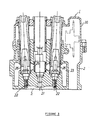
- FIGs. 1 and 2 show a vertical cross-sectional view of an essential part of the in-cylinder injection engine of the invention.
- FIG. 3 is a vertical cross-sectional view of the cylinder head of the in-cylinder injection engine.
- FIG. 4 is a bottom view of the same cylinder head.
- the in-cylinder injection engine of this embodiment is of the four-stroke cycle type with five valves, and its cylinder head 2 as shown in FIG. 4 has three intake valves 3 and two exhaust valves 4.
- the cylinder head 2 is placed over a cylinder block 5.
- a piston 7 for free up and down sliding is inserted in a cylinder 6 mounted in the cylinder block 5 and coupled through a connecting rod 8 to a crankshaft 9.
- Intake passages 10 and exhaust passages 11 are formed in the cylinder head 2.
- the ends of the intake passages 10 and exhaust passages 11 opening into a combustion chamber S, namely intake ports and exhaust ports, are opened and closed by means of the intake and exhaust valves 3 and 4 with appropriate timing to perform necessary gas replacements in the combustion chamber S.
- the intake valves 3 and the exhaust valves 4 are inserted in and supported with respective valve guides 12 and 13 press-fitted into the cylinder head 2; urged toward closing position by means of valve springs 14 and 15; and contacted through valve lifters 16 and 17 with an intake cam 18a and an exhaust cam 19a.
- the intake cam 18a and the exhaust cam 19a are respectively formed integrally with an intake camshaft 18 and an exhaust camshaft 19. As the intake camshaft 18 and the exhaust camshaft 19 are driven to rotate by part of the engine power, the intake valves 3 and the exhaust valves 4 are opened and closed with appropriate timing to perform necessary gas replacements in the combustion chamber S as described above.
- a head cover 20 is placed over the cylinder head 2.
- An injector 21 is disposed in the bore center area (cylinder bore axis area of the cylinder block 5) of the cylinder head 2.
- Two ignition plugs 22 are disposed in the cylinder head 2 on both sides of the injector 21 in the camshaft direction (right-left direction in FIG. 3). As shown in FIG. 4, the two ignition plugs 22 are radially disposed with displacement from the injector 21 toward the exhaust side. In FIG. 3, the ignition plugs 22 are seen with a slight tilt from the cylinder axis toward the camshafts so that the distance between them is slightly widening upward.
- the injector 21 and the ignition plug 22 are respectively sheathed in pipe members 25 and 26 and disposed to face a water jacket 23.
- the in-cylinder injection engine 1 of this embodiment employs the so-called center injection type in which fuel is injected from the injector 21 to the central part of the combustion chamber S, and mixture is ignited and burned by means of the two ignition plugs 22 disposed in the camshaft direction. This enables reliable, uniform combustion of mixture in the combustion chamber S to produce a high output, a low fuel consumption, and improved exhaust gas property.
- the center injection type also provides the advantage of reduction in the amount of fuel adhering to the cylinder wall 6 and resultant small amount of HC emission. This also improves the exhaust gas property.
- the top land of the piston may be formed either convex as shown in FIG. 1 or flat. This makes it easy to form the piston 7.
- FIG. 5 shows a shape of the combustion chamber S provided with a squish area.
- FIG. 5 are also shown the cylinder head 2, the injector 21, and the ignition plugs 22.
- FIG. 6 shows the timing of fuel injection and ignition of the in-cylinder injection type of engine of this embodiment.
- the acronyms TDC and BDC stand for top dead center and bottom dead center, respectively.
- FIGs. 7 and 8 show the cylinder head, in vertical cross section, of the in-cylinder injection engine not falling under the scope of the present invention.
- FIG. 9 is a bottom view of the same cylinder head.
- the in-cylinder injection engine is of the four-stroke cycle type with five valves, and its cylinder head 2 as shown in FIG. 9 has three intake valves 3 (3-1, 3-2, and 3-3), and two exhaust valves 4.
- the intake valve 3-2 of this embodiment in the center is made smaller in diameter than the other two (3-1 and 3-3) located on both sides thereof.
- the cylinder head 2 is placed over the cylinder block 5.
- the piston 7 for free up and down sliding is inserted in the cylinder 6 mounted in the cylinder block 5 and coupled through the connecting rod 8 to the crankshaft 9.
- Intake passages 10 and exhaust passages 11 are formed in the cylinder head 2.
- the ends of the intake passages 10 and exhaust passages 11 opening into the combustion chamber S, namely intake ports and exhaust ports, are opened and closed by means of the intake and exhaust valves 3 and 4 with appropriate timing to perform necessary gas replacements in the combustion chamber S.
- valves 3 and the exhaust valves 4 are inserted in and supported with respective valve guides 12 and 13 which are press-fitted into the cylinder head 2; urged toward closing position by means of valve springs 14 and 15; and contacted through valve lifters 16 and 17 with the intake cam 18a and the exhaust cam 19a.
- the intake cam 18a and the exhaust cam 19a are respectively formed integrally with the intake camshaft 18 and the exhaust camshaft 19. As the intake camshaft 18 and the exhaust camshaft 19 are driven to rotate by part of the engine power, the intake valves 3 and the exhaust valves 4 are opened and closed with appropriate timing to perform necessary gas replacements in the combustion chamber S as described above.
- the cylinder head 2 is covered with the head cover 20 from above.
- the injector 21 and the ignition plug 22 are disposed side by side along the intake-exhaust direction (right-left direction in FIGs. 7 and 9) around the bore center of the cylinder head 2 (around axially central area of each cylinder bore of the cylinder block 5).
- the intake valves 3 and the exhaust valves 4 are disposed around the injector 21 and the ignition plug 22 disposed the intake valves 3 and the exhaust valves 4 (See FIG. 9).
- the injector 21 is disposed on the exhaust side while the ignition plug 22 on the intake side.
- the injector 21 and the ignition plug 22 are disposed with some inclination so that their mutual distance widens toward their outer ends.
- the reference numeral 23 in FIG. 7 denotes the water jacket for cooling water to flow through.
- an electrode portion 22a of the ignition plug 22 is located as shown in FIG. 8 at a higher position on the upper wall of the combustion chamber S than a fuel injection spout 21a of the injector 21.
- the in-cylinder injection engine 1 not falling under the scope of the present invention employs the so-called center injection type in which fuel is injected from the injector 21 to the central part of the combustion chamber S, and the electrode portion 22a of the ignition plug 22 is located at a higher position on the upper wall of the combustion chamber S than the fuel injection spout 2 la of the injector 21. Therefore, atomized fuel from the injector 21 is not directly sprayed over the electrode portion 22a of the ignition plug 22. This enables reliable, uniform combustion of mixture by means of the ignition plug 22, as well as high output, low fuel consumption, and improved exhaust gas property.
- the center injection type also provides the advantage of reduction in the amount of fuel adhering to the wall of the cylinder 6 and resultant small amount of HC emission. This also improves the exhaust gas property.
- the top land of the piston can be formed either convex as shown in FIG. 7 or flat. This makes it easy to form the piston 7.
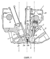
- FIGs. 10 and 11 show the cylinder head, in vertical cross section, of the in-cylinder injection engine.
- FIG. 12 is a bottom view of the cylinder head.
- the same elements as those shown in FIGs. 7 to 9 are provided with the same reference numerals and their descriptions are omitted.
- the fuel injection spout 21 a of the injector 21 is located close to the electrode portion 22a of the ignition plug 22 by tilting the injector 21 largely toward the exhaust side (to the left in FIG. 11).
- the so-called center injection type is also used for the fuel injection, and as shown in FIG. 11, the electrode portion 22a of the ignition plug 22 is located at a higher position on the upper wall of the combustion chamber S than the fuel injection spout 21 a of the injector 21. Therefore, the same effect as that with the engine as shown in FIG. 7 is provided.
- FIG. 13 is a bottom view of the cylinder head of the in-cylinder injection engine.
- the same elements as those shown in FIG. 9 are provided with the same reference numerals.
- the configuration of this engine is the same as that of the engine as shown in FIG. 7 except for the layout direction of the injector 21 and the ignition plug 22.
- the injector 21 and the ignition plug 22 are disposed side by side in the direction (upward and downward direction in FIG. 13) at right angles to the intake-exhaust direction (right and left direction in FIG. 13), and the intake valves 3-1 and 3-3 on both sides are made smaller in diameter than the central intake valve 3-2.
- the so-called center injection type is employed for the fuel injection and, although not shown, the electrode portion of the ignition plug 22 is located at a higher position on the upper wall of the combustion chamber S than the fuel injection spout of the injector 21. Therefore, the same effect as that with the previously described engine as shown in FIG. 7 is provided.
- FIG. 14 shows a cylinder head in vertical cross section of the in-cylinder injection engine of this embodiment.
- FIG. 15 is a bottom view of the cylinder head.
- the same elements as those shown in FIGs. 7 to 9 are provided with the same reference numerals and their descriptions are omitted.
- the injector 21 and the ignition plug 22 are disposed side by side obliquely with displacements toward intake and exhaust sides, with the injector 21 on the intake side of a lower temperature while the ignition plug 22 on the exhaust side. Disposing the injector 21 on the low temperature, intake side in this way prevents carbon from depositing around the fuel injection spout 2 la of the injector 21 and enables to maintain accurate fuel injection rate.
- the injector 21 and the ignition plug 22 are respectively sheathed in pipe members 25 and 26 and disposed to face the water jacket 23.
- the fuel injection is also of the so-called center injection type, and the electrode portion 22a of the ignition plug 22 is located at a higher position on the upper wall of the combustion chamber & than the fuel injection spout of the injector 21. Therefore, the same effect as that with the first embodiment is provided. Further effects are provided, that is, since the injector 21 and the ignition plug 22 are disposed side by side obliquely with displacements toward intake and exhaust sides, all the intake valves 3 (3-1, 3-2, and 3-3) can be made of the same diameter. And, since the injector 21 and the ignition plug 22 are respectively sheathed in pipe members 25 and 26 and disposed to face the water jacket 23, the injector 21 and the ignition plug 22 are effectively cooled with the water flowing through the water jacket 23.
- the injector 21 is disposed on the intake side of a lower temperature and the ignition plug 22 on the exhaust side, it is also possible to dispose inversely, with the injector 21 on the exhaust side and the ignition plug on the intake side of a lower temperature. Such an arrangement with the ignition plug on the intake side of a lower temperature makes it possible to effectively prevent knocking from occurring.
- this invention employs the center injection type in which fuel is injected from the injector to the central part of the combustion chamber, and mixture is ignited and burned by means of the two ignition plugs disposed in the camshaft direction. This enables reliable, uniform combustion of mixture in the combustion chamber to produce a high output, a low fuel consumption, and improved exhaust gas property.
- this embodiment employs the center injection type in which fuel is injected from the injector to the central part of the combustion chamber, and the electrode portion of the ignition plug is located at a higher position on the upper wall of the combustion chamber than the fuel injection spout of the injector. Therefore, atomized fuel from the injector is not directly sprayed over the electrode portion of the ignition plug, and the mixture is ignited with the ignition plug and burned reliably and uniformly to provide high output, low fuel consumption, and improved exhaust gas property.
Landscapes
- Engineering & Computer Science (AREA)
- Chemical & Material Sciences (AREA)
- Combustion & Propulsion (AREA)
- Mechanical Engineering (AREA)
- General Engineering & Computer Science (AREA)
- Cylinder Crankcases Of Internal Combustion Engines (AREA)
- Combustion Methods Of Internal-Combustion Engines (AREA)
- Ignition Installations For Internal Combustion Engines (AREA)
Claims (10)
- Brennkraftmaschine (1) eines In- Zylinder- Einspritztyps mit zumindest einem Einspritzer (21) und zumindest einer Zündkerze (22), wobei der Einspritzer (21) und / oder zumindest eine der Zündkerzen (22) in einer Bohrungsmittenbereich eines Zylinders (6) angeordnet sind, während der Einspritzer (21) und eine Zündkerze (22) nebeneinander angeordnet sind,
dadurch gekennzeichnet, dass der Einspritzer (21) und die Zündkerze (22) schräg mit Verlagerungen in die Richtung zu den Einlass- und Auslassseiten angeordnet sind, mit dem Einspritzer (21) an der Einlassseite und der Zündkerze (22) an der Auslaßseite. - Brennkraftmaschine nach Anspruch 1, dadurch gekennzeichnet, dass der Einspritzer oder die Einspritzer (21) derart angeordnet sind, dass ein Elektrodenbereich (22a) der Zündkerze oder der Zündkerzen (22) frei von einem direkten Kraftstoffeinsprühnebel sind.
- Brennkraftmaschine nach Anspruch 1 oder 2, dadurch gekennzeichnet, dass der Einspritzer (21) in dem Bohrungsmittenbereich jedes Zylinders (6) angeordnet ist und dass zwei Zündkerzen (22) in einer Nockenwellenrichtung auf beiden Seiten des Einspritzers (21) angeordnet sind.
- Brennkraftmaschine nach zumindest einem der vorhergehenden Ansprüche 1 bis 3, dadurch gekennzeichnet, dass die Zündkerze (22) in Richtung einer Nockenwelle (18, 199 und relativ zu einer Zylinderachse geneigt angeordnet ist.
- Brennkraftmaschine nach zumindest einem der vorhergehenden Ansprüche 1 bis 4, dadurch gekennzeichnet, dass ein Zylinderkopf (2) mit drei Einlassventifen (3) und zwei Auslassventilen (4) versehen ist.
- Brennkraftmaschine nach Anspruch 1, dadurch gekennzeichnet, dass der Einspritzer (21) und die Zündkerze (22) nebeneinander in dem Mittelbereich jeder Zylinderbohrung angeordnet sind, und ein Elektrodenabschnitt (22a) der Zündkerze (22) auf einer höheren Position an einer oberen Wand einer Brennkammer (S) als eine Kraftstoffeinspritzausfass (21a) des Einspritzers (21) angeordnet ist.
- Brennkraftmaschine nach Anspruch 6, dadurch gekennzeichnet, dass der Einspritzer (21) und die Zündkerze (22) nebeneinander im Wesentlichen in rechten Winkeln zu einer Nockenwelle (18, 19) angeordnet sind und dass zumindest jeweils eine von Ventilantriebsvorrichtungen für ein Einlass- (3) und ein Auslassventil (4) vom Kipphebel-Typ (24) ist.
- Brennkraftmaschine nach zumindest einem der vorhergehenden Ansprüche 5 bis 7, dadurch gekennzeichnet, dass zumindest eines der Einlassventile (3) im Durchmesser kleiner als die anderen Einlassventile (3) in Abhängigkeit von der Richtung der Nebeneinanderanordnung des Einspritzers (21) und der Zündkerze (22) gemacht ist.
- Brennkraftmaschine nach zumindest einem der vorhergehenden Ansprüche 1 bis 8, dadurch gekennzeichnet, dass ein Spitzenboden eines Kolbens (7) flach oder konvex gestaltet ist.
- Brennkraftmaschine nach zumindest einem der vorhergehenden Ansprüche 1 bis 9, dadurch gekennzeichnet, dass der Einspritzer (21) und die Zündkerze (22) jeweils in Rohrteilen (25, 26) ummantelt und angeordnet sind, um einem Wassermantel (23) zugewandt zu sein.
Applications Claiming Priority (4)
| Application Number | Priority Date | Filing Date | Title |
|---|---|---|---|
| JP18046398 | 1998-06-26 | ||
| JP10180463A JP2000008943A (ja) | 1998-06-26 | 1998-06-26 | 筒内噴射式エンジン |
| JP10184851A JP2000018090A (ja) | 1998-06-30 | 1998-06-30 | 筒内噴射式エンジン |
| JP18485198 | 1998-06-30 |
Publications (3)
| Publication Number | Publication Date |
|---|---|
| EP0967370A2 EP0967370A2 (de) | 1999-12-29 |
| EP0967370A3 EP0967370A3 (de) | 2000-09-27 |
| EP0967370B1 true EP0967370B1 (de) | 2005-03-30 |
Family
ID=26499982
Family Applications (1)
| Application Number | Title | Priority Date | Filing Date |
|---|---|---|---|
| EP99112276A Expired - Lifetime EP0967370B1 (de) | 1998-06-26 | 1999-06-25 | Brennkraftmaschine |
Country Status (3)
| Country | Link |
|---|---|
| US (1) | US20010003281A1 (de) |
| EP (1) | EP0967370B1 (de) |
| DE (1) | DE69924432T2 (de) |
Families Citing this family (14)
| Publication number | Priority date | Publication date | Assignee | Title |
|---|---|---|---|---|
| US6143496A (en) * | 1997-04-17 | 2000-11-07 | Cytonix Corporation | Method of sampling, amplifying and quantifying segment of nucleic acid, polymerase chain reaction assembly having nanoliter-sized sample chambers, and method of filling assembly |
| DE19928838C1 (de) * | 1999-06-24 | 2001-02-15 | Otmar Gaehrken | Zylinderkopf |
| DE10035239B4 (de) * | 2000-07-20 | 2011-04-21 | Daimler Ag | Brennkraftmaschine |
| JP2002183593A (ja) * | 2000-09-20 | 2002-06-28 | Masami Isomura | 看板情報検索システム |
| JP3846436B2 (ja) * | 2003-03-10 | 2006-11-15 | マツダ株式会社 | 直噴ディーゼルエンジンのシリンダヘッド部構造 |
| DE102005011224B4 (de) * | 2005-03-11 | 2013-05-29 | Audi Ag | Zylinderkopf |
| JP2006258053A (ja) * | 2005-03-18 | 2006-09-28 | Nissan Motor Co Ltd | 直接噴射式内燃機関およびその燃焼方法 |
| JP5315185B2 (ja) * | 2009-09-16 | 2013-10-16 | 本田技研工業株式会社 | 内燃機関の点火装置の取り付け構造 |
| US20150176521A1 (en) * | 2012-06-18 | 2015-06-25 | Perusahaan Otomobil Nasional Sdn Bhd | Method and apparatus for cooling a cylinder head |
| US10309339B2 (en) * | 2015-05-25 | 2019-06-04 | Nissan Motor Co., Ltd. | Internal combustion engine |
| DE102015113805A1 (de) | 2015-08-20 | 2017-02-23 | Dr. Ing. H.C. F. Porsche Aktiengesellschaft | Zylinderkopf für eine Brennkraftmaschine mit Brennstoffeinspritzung |
| JP6337877B2 (ja) * | 2015-12-10 | 2018-06-06 | マツダ株式会社 | 内燃機関の燃焼室構造 |
| GB2611103A (en) * | 2021-09-28 | 2023-03-29 | Jcb Res | Internal combustion engine |
| US12404802B2 (en) * | 2023-04-13 | 2025-09-02 | Saudi Arabian Oil Company | Combustion chamber for high performance H2 direct injection engine |
Citations (1)
| Publication number | Priority date | Publication date | Assignee | Title |
|---|---|---|---|---|
| US4770138A (en) * | 1986-06-19 | 1988-09-13 | Nippon Clen Engine Research Institute Co. Ltd. | Fuel injection type internal combustion engine |
Family Cites Families (10)
| Publication number | Priority date | Publication date | Assignee | Title |
|---|---|---|---|---|
| US4364342A (en) * | 1980-10-01 | 1982-12-21 | Ford Motor Company | Ignition system employing plasma spray |
| GB2112859B (en) * | 1981-12-16 | 1985-07-17 | John Heath Greenhough | Spark ignition direct injection i.c.engine |
| JPS6011626A (ja) * | 1983-06-29 | 1985-01-21 | Fuji Heavy Ind Ltd | 分割燃焼式エンジンの燃焼室 |
| DE3340445A1 (de) * | 1983-11-09 | 1985-05-15 | Motoren-Werke Mannheim AG vorm. Benz Abt. stationärer Motorenbau, 6800 Mannheim | Zylinderkopf |
| JP2615134B2 (ja) * | 1988-05-30 | 1997-05-28 | ヤマハ発動機株式会社 | 4サイクルエンジンの吸気装置 |
| US5605125A (en) * | 1994-11-18 | 1997-02-25 | Yaoita; Yasuhito | Direct fuel injection stratified charge engine |
| DE19510053C2 (de) * | 1994-04-08 | 1997-09-04 | Ford Werke Ag | Mehrzylinder-Hubkolben-Verbrennungsmotor |
| JPH108971A (ja) * | 1996-06-19 | 1998-01-13 | Yamaha Motor Co Ltd | 筒内燃料噴射式エンジン |
| JP3743896B2 (ja) * | 1996-10-31 | 2006-02-08 | 富士重工業株式会社 | 筒内噴射式エンジン |
| DE19728946A1 (de) * | 1997-07-07 | 1999-01-14 | Audi Ag | Zylinderkopf einer direkteinspritzenden Brennkraftmaschine |
-
1999
- 1999-06-25 EP EP99112276A patent/EP0967370B1/de not_active Expired - Lifetime
- 1999-06-25 US US09/340,339 patent/US20010003281A1/en not_active Abandoned
- 1999-06-25 DE DE69924432T patent/DE69924432T2/de not_active Expired - Fee Related
Patent Citations (1)
| Publication number | Priority date | Publication date | Assignee | Title |
|---|---|---|---|---|
| US4770138A (en) * | 1986-06-19 | 1988-09-13 | Nippon Clen Engine Research Institute Co. Ltd. | Fuel injection type internal combustion engine |
Also Published As
| Publication number | Publication date |
|---|---|
| DE69924432D1 (de) | 2005-05-04 |
| DE69924432T2 (de) | 2005-08-18 |
| US20010003281A1 (en) | 2001-06-14 |
| EP0967370A3 (de) | 2000-09-27 |
| EP0967370A2 (de) | 1999-12-29 |
Similar Documents
| Publication | Publication Date | Title |
|---|---|---|
| US4741302A (en) | Internal combustion engine | |
| EP0967370B1 (de) | Brennkraftmaschine | |
| US4192265A (en) | Combustion promoting device of a multi-cylinder engine | |
| US5305720A (en) | Internal combustion engine | |
| US5735240A (en) | Direct injected engine | |
| US6499457B2 (en) | In-cylinder injection gasoline engine | |
| EP1199462A2 (de) | Brennkraftmaschine und Kolben für eine Brennkraftmaschine | |
| JPS5846667B2 (ja) | 多気筒内燃機関の排気ガス再循環装置 | |
| GB2288210A (en) | Direct-injection spark-ignition engine | |
| US8820292B2 (en) | Spark-ignition internal combustion engine | |
| US5529038A (en) | Direct injected engine | |
| US4023541A (en) | Combustion chamber for internal-combustion engine | |
| US6708667B2 (en) | Combustion chamber structure of in-cylinder fuel injection type engine | |
| EP1148217A2 (de) | Einlasssteuervorrichtung für eine Brennkraftmaschine | |
| US4998513A (en) | 4-stroke, stratified gas engine | |
| CA2318924A1 (en) | Barrier divided combustion chamber for fuel injected two-stroke engine | |
| CA1075988A (en) | Internal combustion engine having two spark plugs for each combustion chamber and exhaust gas recirculation circuit | |
| CA2186548A1 (en) | Internal combustion engine | |
| EP0971116B1 (de) | Brennkraftmaschine | |
| JP2534032Y2 (ja) | 予燃焼室付ディーゼル機関 | |
| EP0914549B1 (de) | Zwei- oder viertakt pkw kleinmotor mit schichtladung | |
| WO1990014508A1 (en) | A piston cylinder combination with cylinder wall having valve ports and combustion chamber | |
| JP2000018090A (ja) | 筒内噴射式エンジン | |
| US3699933A (en) | Valve operating arrangement for internal combustion reciprocating engines | |
| JPH0533650A (ja) | 2サイクル内燃機関 |
Legal Events
| Date | Code | Title | Description |
|---|---|---|---|
| PUAI | Public reference made under article 153(3) epc to a published international application that has entered the european phase |
Free format text: ORIGINAL CODE: 0009012 |
|
| AK | Designated contracting states |
Kind code of ref document: A2 Designated state(s): DE ES FR GB IT |
|
| AX | Request for extension of the european patent |
Free format text: AL;LT;LV;MK;RO;SI |
|
| PUAL | Search report despatched |
Free format text: ORIGINAL CODE: 0009013 |
|
| AK | Designated contracting states |
Kind code of ref document: A3 Designated state(s): AT BE CH CY DE DK ES FI FR GB GR IE IT LI LU MC NL PT SE |
|
| AX | Request for extension of the european patent |
Free format text: AL;LT;LV;MK;RO;SI |
|
| 17P | Request for examination filed |
Effective date: 20010322 |
|
| AKX | Designation fees paid |
Free format text: DE ES FR GB IT |
|
| 17Q | First examination report despatched |
Effective date: 20031107 |
|
| GRAP | Despatch of communication of intention to grant a patent |
Free format text: ORIGINAL CODE: EPIDOSNIGR1 |
|
| GRAS | Grant fee paid |
Free format text: ORIGINAL CODE: EPIDOSNIGR3 |
|
| GRAA | (expected) grant |
Free format text: ORIGINAL CODE: 0009210 |
|
| AK | Designated contracting states |
Kind code of ref document: B1 Designated state(s): DE ES FR GB IT |
|
| REG | Reference to a national code |
Ref country code: GB Ref legal event code: FG4D |
|
| REF | Corresponds to: |
Ref document number: 69924432 Country of ref document: DE Date of ref document: 20050504 Kind code of ref document: P |
|
| PG25 | Lapsed in a contracting state [announced via postgrant information from national office to epo] |
Ref country code: ES Free format text: LAPSE BECAUSE OF FAILURE TO SUBMIT A TRANSLATION OF THE DESCRIPTION OR TO PAY THE FEE WITHIN THE PRESCRIBED TIME-LIMIT Effective date: 20050711 |
|
| PLBE | No opposition filed within time limit |
Free format text: ORIGINAL CODE: 0009261 |
|
| STAA | Information on the status of an ep patent application or granted ep patent |
Free format text: STATUS: NO OPPOSITION FILED WITHIN TIME LIMIT |
|
| ET | Fr: translation filed | ||
| 26N | No opposition filed |
Effective date: 20060102 |
|
| PGFP | Annual fee paid to national office [announced via postgrant information from national office to epo] |
Ref country code: IT Payment date: 20090619 Year of fee payment: 11 |
|
| PGFP | Annual fee paid to national office [announced via postgrant information from national office to epo] |
Ref country code: GB Payment date: 20090624 Year of fee payment: 11 Ref country code: DE Payment date: 20090619 Year of fee payment: 11 |
|
| GBPC | Gb: european patent ceased through non-payment of renewal fee |
Effective date: 20100625 |
|
| REG | Reference to a national code |
Ref country code: FR Ref legal event code: ST Effective date: 20110228 |
|
| PG25 | Lapsed in a contracting state [announced via postgrant information from national office to epo] |
Ref country code: IT Free format text: LAPSE BECAUSE OF NON-PAYMENT OF DUE FEES Effective date: 20100625 |
|
| PG25 | Lapsed in a contracting state [announced via postgrant information from national office to epo] |
Ref country code: DE Free format text: LAPSE BECAUSE OF NON-PAYMENT OF DUE FEES Effective date: 20110101 |
|
| PG25 | Lapsed in a contracting state [announced via postgrant information from national office to epo] |
Ref country code: FR Free format text: LAPSE BECAUSE OF NON-PAYMENT OF DUE FEES Effective date: 20100630 |
|
| PG25 | Lapsed in a contracting state [announced via postgrant information from national office to epo] |
Ref country code: GB Free format text: LAPSE BECAUSE OF NON-PAYMENT OF DUE FEES Effective date: 20100625 |
|
| PGFP | Annual fee paid to national office [announced via postgrant information from national office to epo] |
Ref country code: FR Payment date: 20090611 Year of fee payment: 11 |