EP0967386A2 - Injecteur de combustible - Google Patents
Injecteur de combustible Download PDFInfo
- Publication number
- EP0967386A2 EP0967386A2 EP99303895A EP99303895A EP0967386A2 EP 0967386 A2 EP0967386 A2 EP 0967386A2 EP 99303895 A EP99303895 A EP 99303895A EP 99303895 A EP99303895 A EP 99303895A EP 0967386 A2 EP0967386 A2 EP 0967386A2
- Authority
- EP
- European Patent Office
- Prior art keywords
- needle
- bore
- injector
- spring
- spring abutment
- Prior art date
- Legal status (The legal status is an assumption and is not a legal conclusion. Google has not performed a legal analysis and makes no representation as to the accuracy of the status listed.)
- Withdrawn
Links
- 239000000446 fuel Substances 0.000 title claims abstract description 52
- 239000012530 fluid Substances 0.000 claims description 12
- 230000015572 biosynthetic process Effects 0.000 description 10
- 238000005755 formation reaction Methods 0.000 description 10
- 238000002347 injection Methods 0.000 description 10
- 239000007924 injection Substances 0.000 description 10
- 230000004048 modification Effects 0.000 description 6
- 238000012986 modification Methods 0.000 description 6
- 238000004891 communication Methods 0.000 description 3
- 230000006835 compression Effects 0.000 description 3
- 238000007906 compression Methods 0.000 description 3
- 238000000034 method Methods 0.000 description 3
- 238000003466 welding Methods 0.000 description 3
- 238000002485 combustion reaction Methods 0.000 description 2
- 238000005553 drilling Methods 0.000 description 2
- 229910010293 ceramic material Inorganic materials 0.000 description 1
- 230000001419 dependent effect Effects 0.000 description 1
- 230000010339 dilation Effects 0.000 description 1
- 239000002828 fuel tank Substances 0.000 description 1
- 238000004519 manufacturing process Methods 0.000 description 1
- 238000007789 sealing Methods 0.000 description 1
- 238000011144 upstream manufacturing Methods 0.000 description 1
Images


Classifications
-
- F—MECHANICAL ENGINEERING; LIGHTING; HEATING; WEAPONS; BLASTING
- F02—COMBUSTION ENGINES; HOT-GAS OR COMBUSTION-PRODUCT ENGINE PLANTS
- F02M—SUPPLYING COMBUSTION ENGINES IN GENERAL WITH COMBUSTIBLE MIXTURES OR CONSTITUENTS THEREOF
- F02M61/00—Fuel-injectors not provided for in groups F02M39/00 - F02M57/00 or F02M67/00
- F02M61/04—Fuel-injectors not provided for in groups F02M39/00 - F02M57/00 or F02M67/00 having valves, e.g. having a plurality of valves in series
- F02M61/08—Fuel-injectors not provided for in groups F02M39/00 - F02M57/00 or F02M67/00 having valves, e.g. having a plurality of valves in series the valves opening in direction of fuel flow
-
- F—MECHANICAL ENGINEERING; LIGHTING; HEATING; WEAPONS; BLASTING
- F02—COMBUSTION ENGINES; HOT-GAS OR COMBUSTION-PRODUCT ENGINE PLANTS
- F02M—SUPPLYING COMBUSTION ENGINES IN GENERAL WITH COMBUSTIBLE MIXTURES OR CONSTITUENTS THEREOF
- F02M61/00—Fuel-injectors not provided for in groups F02M39/00 - F02M57/00 or F02M67/00
- F02M61/16—Details not provided for in, or of interest apart from, the apparatus of groups F02M61/02 - F02M61/14
- F02M61/18—Injection nozzles, e.g. having valve seats; Details of valve member seated ends, not otherwise provided for
-
- F—MECHANICAL ENGINEERING; LIGHTING; HEATING; WEAPONS; BLASTING
- F02—COMBUSTION ENGINES; HOT-GAS OR COMBUSTION-PRODUCT ENGINE PLANTS
- F02M—SUPPLYING COMBUSTION ENGINES IN GENERAL WITH COMBUSTIBLE MIXTURES OR CONSTITUENTS THEREOF
- F02M51/00—Fuel-injection apparatus characterised by being operated electrically
- F02M51/06—Injectors peculiar thereto with means directly operating the valve needle
- F02M51/0603—Injectors peculiar thereto with means directly operating the valve needle using piezoelectric or magnetostrictive operating means
-
- F—MECHANICAL ENGINEERING; LIGHTING; HEATING; WEAPONS; BLASTING
- F02—COMBUSTION ENGINES; HOT-GAS OR COMBUSTION-PRODUCT ENGINE PLANTS
- F02M—SUPPLYING COMBUSTION ENGINES IN GENERAL WITH COMBUSTIBLE MIXTURES OR CONSTITUENTS THEREOF
- F02M61/00—Fuel-injectors not provided for in groups F02M39/00 - F02M57/00 or F02M67/00
- F02M61/04—Fuel-injectors not provided for in groups F02M39/00 - F02M57/00 or F02M67/00 having valves, e.g. having a plurality of valves in series
- F02M61/10—Other injectors with elongated valve bodies, i.e. of needle-valve type
- F02M61/12—Other injectors with elongated valve bodies, i.e. of needle-valve type characterised by the provision of guiding or centring means for valve bodies
-
- F—MECHANICAL ENGINEERING; LIGHTING; HEATING; WEAPONS; BLASTING
- F02—COMBUSTION ENGINES; HOT-GAS OR COMBUSTION-PRODUCT ENGINE PLANTS
- F02M—SUPPLYING COMBUSTION ENGINES IN GENERAL WITH COMBUSTIBLE MIXTURES OR CONSTITUENTS THEREOF
- F02M2200/00—Details of fuel-injection apparatus, not otherwise provided for
- F02M2200/70—Linkage between actuator and actuated element, e.g. between piezoelectric actuator and needle valve or pump plunger
- F02M2200/701—Linkage between actuator and actuated element, e.g. between piezoelectric actuator and needle valve or pump plunger mechanical
Definitions
- This invention relates to a fuel injector for use in supplying fuel to a combustion space of a compression ignition internal combustion engine.
- the invention relates to an injector of the outwardly opening type which can be controlled using an electronic control arrangement.
- Such an injector is suitable for use in, for example, a common rail type fuel system.
- an outwardly opening fuel injector comprising a valve needle movable within a bore and engageable with a seating to control the supply of fuel from the bore, the needle being moveable outwardly of the bore to move the needle away from its seating, the needle being biased towards its seating by a spring, the spring engaging a spring abutment arrangement associated with a part of the needle remote from the part thereof engageable with the seating, the spring abutment arrangement further acting to guide movement of the needle.
- the spring abutment arrangement may comprise a spring abutment member carried by the part of the needle remote from the part thereof engageable with the seating.
- the spring abutment member conveniently takes the form of a sleeve which surrounds part of the needle.
- the sleeve may be in screw threaded engagement with the needle, or alternatively may be secured thereto by welding, using a spring clip, or using any other suitable technique.
- the spring abutment member may be arranged to guide movement of the needle by engaging part of the wall of the bore within which the needle is located.
- the spring abutment member may be arranged to engage the wall of a second bore formed in a separate member, the second bore extending coaxially with the bore within which the needle is located.
- the injector conveniently further comprises a piezo-electric actuator arrangement.
- the piezo-electric actuator arrangement may comprise an actuator arranged to move a piston to control the fluid pressure within a control chamber, part of the needle being exposed to the fluid pressure within the control chamber.
- the spring abutment arrangement may, alternatively, comprise a guide region arranged to guide the needle for sliding movement, a fixing region for securing the guide region to the needle and an abutment region arranged to engage the spring, the guide region transmitting the spring load from the abutment region to the fixing region.
- Two of the regions may, if desired, be integral with one another.
- the guide region may be slidable within a bore formed in a sleeve located with a nozzle body.
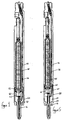
- the injector illustrated in Figures 1 and 2 comprises a nozzle body 10 having a through bore 12 formed therein.
- the bore 12 is shaped, adjacent its lower end, to define a seating 14.
- a valve needle 16 is located within the bore 12, the needle 16 including, at its lower end, a region 18 of enlarged diameter which is engageable with the seating 14 to control communication between a part of the bore 12 upstream of the seating 14 and a chamber 20 defined between part of the bore 12 downstream of the seating 14 and a part of the enlarged diameter region 18 of the needle 16.
- a plurality of outlet openings 22 are provided in the nozzle body 10 and arranged such that, as the needle 16 moves downwardly away from the seating 14, the openings 22 come into communication with the chamber 20 to permit delivery of fuel through the openings 22.
- the upper end of the needle 16 is provided with a screw thread formation 24 which engages a corresponding formation provided upon the interior of a spring abutment arrangement in the form of a spring abutment member 26.
- the spring abutment member 26 takes the form of a cylindrical sleeve of outer diameter slightly smaller than the diameter of the adjacent part of the bore 12. It will be appreciated that the engagement of the spring abutment member 26 with the wall of the bore 12, and the engagement of the region 18 of the needle 16 with the lower end of the bore 12 guides the needle 16 for movement along the axis of the bore 12.
- the bore 12 defines a step 28 with which a second spring abutment member 30 engages.
- a compression spring 32 is located between the spring abutment member 26 and the second spring abutment member 32 to bias the valve needle 16 in an upward direction, in the orientation illustrated, the bias the region 18 of the needle 16 into engagement with the seating 14.
- the screw thread formation 24 is conveniently of generous root radius and of a suitable pitch to allow the spring 32 to pass the screw thread formation 24 by rotating the spring 32 relative to the needle 16, the spring abutment member 26 being secured to the needle 16 after the spring 32 has been located upon the needle 16.
- Such a screw thread formation further has the advantage that stress concentrations are reduced. It has been found that the use of a small, close fitting thread can form a reasonably good seal due to the long flow path for escaping fluid.
- the spring abutment member 26 is conveniently secured to the needle 16 to avoid undesirable relative rotation therebetween, in use, by inserting a pin 34 though openings provided in the spring abutment member 26, the pin 34 extending within a groove or other formation formed in the upper end surface of the needle 16.
- the pin may engage within castellation like formations provided in the spring abutment member.
- a conventional lock nut, lock screw or other thread locking technique may be used.
- the bore 12 communicates with a supply passage 36 through which fuel is supplied to the bore 12 from a suitable source of fuel under pressure, in use, for example the common rail of a common rail fuel supply system which is charged with fuel at a high pressure by an appropriate fuel pump.
- a suitable source of fuel under pressure for example the common rail of a common rail fuel supply system which is charged with fuel at a high pressure by an appropriate fuel pump.
- openings 38 are provided in the second spring abutment member 30.
- the upper end faces of the valve needle 16 and the spring abutment member 26 are exposed to the fluid pressure within the control chamber 44, thus the fluid pressure within the control chamber 44 applies a force to the needle 16 which acts against the action of the spring 32 and the action of the fluid pressure within the nozzle body 10.
- the piston housing 40 engages a nozzle holder 46 within which a piezo-electric actuator 48 in the form of a stack of piezo ceramic material is located.
- the lower end of the actuator 48 engages an anvil 50 which, in turn, engages a slip plate 52.
- the slip plate 52 engages the upper end of the piston member 42.
- the slip plate 52 and the adjacent end of the piston member 42 are shaped to compensate for slight misalignment between the axis of the actuator 48 and that of the piston member 42.
- a spring 54 is engaged between the piston member 42 and the upper surface of the piston housing 40 to bias the piston member 42 towards the actuator 48.
- the spring 54 takes the form of a wave spring, but it will be appreciated that other types of spring, for example a disc spring or a helical compression spring, could be used.
- the nozzle body 10 and piston housing 40 are secured to the nozzle holder 46 by a cap nut 64.
- the fuel pressure within the control chamber 44 is therefore relatively low.
- An optional radial seal, such as an 'O' ring, may be provided between the slip plate 52 and the bore of the nozzle holder 46. This would substantially eliminate the flow of fuel from the control chamber 44 to the low pressure drain reservoir.
- the actuator When injection is to commence, the actuator is energised to extend in length resulting in movement of the piston member 42 against the action of the spring 54. Such movement pressurizes the fuel within the control chamber 44 thus increasing the downward force applied to the needle 16, and a point will be reached beyond which the needle 16 is able to move in a downward direction, outward of the bore 12, to permit fuel to flow to the chamber 20 and through one or more of the openings 22.
- the rate at which fuel can escape from the control chamber 44 to the low pressure drain reservoir is chosen to be at a sufficiently low level that the pressure within the control chamber 44 remains high throughout the desired injection period.
- the rate at which fuel is delivered is dependent upon the number of openings 22 which are brought into communication with the chamber 20 by the movement of the needle 16.
- the distance through which the needle 16 moves depends upon the magnitude of the extension of the actuator 48.
- the rate of injection can be controlled by appropriate control of the extension of the actuator 48.
- the actuator 48 is deenergised and returns to substantially its original length.
- the piston member 42 moves under the action of the spring 54, reducing the fluid pressure within the control chamber 44 thus reducing the magnitude of the downward force applied to the needle 16, and as a result the needle 16 is able to return into engagement with the seating 14 under the action of the spring 32.
- the injector fails during injection, the leakage of fuel from the control chamber 44 to the low pressure drain will eventually cause the fuel pressure within the control chamber 44 to fall to a sufficiently low level to terminate injection, thus the injector is fail-safe.
- the leakage of fuel from the bore 12 to the control chamber 44 compensates for gradual changes in the length of the actuator 48, for example resulting from temperature changes.
- Figure 3 illustrates a modification in which the spring abutment member 26 is secured to the upper end of the needle 16 by welding after appropriate location of the spring 32 rather than using a screw thread formation
- Figure 4 illustrates an arrangement in which the spring abutment member 26 is secured in position using a spring clip 56.
- the presence of fuel under pressure between the needle 16 and the spring abutment member 26 may expand the spring abutment member 26 to compensate for dilation of the bore 12, thus reducing leakage of fuel from the bore 12.
- FIG. 5 and 6 differs from that described hereinbefore in that a distance piece 58 is located between the nozzle body 10 and the piston housing 40, thus allowing a spring of relatively large diameter to be used.
- the spring abutment member 26 engages the wall of a second bore 60 extending through the distance piece 58 in order guide movement of the needle 16.
- the second bore 60 must be coaxial with the bore 12 of the nozzle body 10, and this is achieved by a plurality of fingers 62 which are integral with the distance piece 58, the fingers 62 defining the lower end of the bore 60.
- the fingers 62 locate, in use, within the upper end of the bore 12 to ensure that the bore 12 is coaxial with the second bore 60.
- the fingers 62 further define a plurality of flow paths along which fuel flows, in use, from the supply passage 36 to the bore 12.
- Figure 7 illustrates a modification which can be incorporated into any of the embodiments described hereinbefore.
- the lower end of the needle 16 protrudes from the bore 12, the lower end of the needle 16 being of increased diameter and being engageable with a seating defined around a lower end of the bore 12.
- the needle 16 is provided with a plurality of outlet openings 22 a which are positioned in axially spaced locations such that the number of openings 22 a through which fuel can be delivered at any instant is controlled by controlling the position of the needle 16.
- the openings 22 a communicate with the interior of the bore 12 through drillings 22 b provided in the needle 16.
- Figure 8 illustrates a fuel injector which, in many respects, is similar to or identical to the arrangements described hereinbefore, and only the important distinctions between the arrangement of Figure 8 and those described hereinbefore will be described.
- the spring abutment arrangement comprises a sleeve which is screw-threaded upon an end region of the needle.
- the spring abutment arrangement comprises a guide region in the form of a sleeve 70 which surrounds part of a needle 71.
- the diameter of the sleeve 70 and the adjacent part of the needle 71 is such as to ensure that fuel is only able to escape therebetween at a restricted rate.
- the sleeve 70 is slidable within a bore formed in a hollow cylindrical member 72 which is received within an upper part of the bore 73 within which the needle 71 is received and moveable.
- the sleeve 70 and member 72 are a sufficiently good fit that the sleeve 70 is able to slide within the bore of the member 72, but leakage therebetween is restricted to a very low rate.
- the lower end of the sleeve 70 in the orientation illustrated, abuts an annular spring abutment member 74 which engages the upper end of a spring 75, the other end of which engages a spring abutment member 76 located against a step formed in the bore 73.
- the upper end of the sleeve 70 abuts a fixing member in the form of a nut 77 which is in screw-threaded engagement with the upper end region of the needle 71.
- the nut 77 is conveniently provided with a formation 78 permitting the introduction of a fixing pin which cooperates with both the nut 77 and the needle 71 to secure the nut 77 against rotation relative to the needle 71.
- the pin and the formation 78 may be omitted, and instead the nut 77 secured against rotation relative to the needle 71 by means of welding, using a spring clip or any other suitable technique.
- the nut 77 is received within a bore 79 formed in a distance piece 80, the bore 79 defining a chamber which forms part of a control chamber, the fuel pressure within which is controlled by means of an actuator arrangement, for example of the type illustrated in Figures 2 and 6.
- the bore 79 is of reduced diameter compared to the part of the bore 73 within which the member 72 is located. It will be appreciated, therefore, that the lower surface of the distance piece 80 adjacent the bore 79 defines a step against which the member 72 is engageable.
- the dimensions of the needle 71 are such that the application of fuel under pressure to the bore 73 applies an upwardly directed force to the needle 71. This force results from the diameter of the sleeve 70 being greater than the diameter of the lower end of the needle 71 where it is guided for sliding movement in the bore 73.
- the action of the spring 75 serves to assist the action of the fuel under pressure in urging the needle in an upward direction, the action of the spring 75, the spring load being applied to the needle 71 through the abutment member 74, sleeve 70 and nut 77.
- the actuator When fuel injection is to occur, the actuator is energized to increase the fuel pressure within the chamber defined, in part, by the bore 79, thus applying a downwardly directed force to the needle 71. A point will be reached beyond which the magnitude of the downwardly directed force will be sufficient to cause the needle 71 to move against the action of the spring 75 and the fuel under pressure within the bore 73 to a position in which fuel injection can occur. Fuel injection is terminated by relieving the fuel pressure within the control chamber defined, in part, by the bore 79, the needle 71 returning to the position illustrated under the action of the spring 75 and the fuel pressure within the bore 73.
- the sleeve 70 may be formed integrally with either the spring abutment member 74 or the nut 77. It will further be appreciated that as the member 72 forms a substantially fluid tight seal with the distance piece 80, the fit of the member 72 within the bore 73 need not be a sealing fit, and the member 72 can adopt a position in which the needle 71 is held substantially co-axially with the bore 73, compensating for any slight manufacturing inaccuracies.
- the diameter of the member 72 is immaterial for the purposes of controlling the operation of the injector, unlike the arrangements illustrated in Figures 1 to 4, it will be appreciated that the diameter of the member 72 can be chosen to ensure that the bore 73 is of diameter sufficient to enable the spring 75 to be of a desired diameter and rate. The operation of the injector can therefore be optimised.
Landscapes
- Engineering & Computer Science (AREA)
- Chemical & Material Sciences (AREA)
- Combustion & Propulsion (AREA)
- Mechanical Engineering (AREA)
- General Engineering & Computer Science (AREA)
- Fuel-Injection Apparatus (AREA)
Applications Claiming Priority (2)
| Application Number | Priority Date | Filing Date | Title |
|---|---|---|---|
| GBGB9811649.4A GB9811649D0 (en) | 1998-05-29 | 1998-05-29 | Fuel injector |
| GB9811649 | 1998-05-29 |
Publications (2)
| Publication Number | Publication Date |
|---|---|
| EP0967386A2 true EP0967386A2 (fr) | 1999-12-29 |
| EP0967386A3 EP0967386A3 (fr) | 2000-12-06 |
Family
ID=10832963
Family Applications (1)
| Application Number | Title | Priority Date | Filing Date |
|---|---|---|---|
| EP99303895A Withdrawn EP0967386A3 (fr) | 1998-05-29 | 1999-05-19 | Injecteur de combustible |
Country Status (5)
| Country | Link |
|---|---|
| US (1) | US6224001B1 (fr) |
| EP (1) | EP0967386A3 (fr) |
| JP (1) | JPH11351098A (fr) |
| KR (1) | KR19990088648A (fr) |
| GB (1) | GB9811649D0 (fr) |
Cited By (6)
| Publication number | Priority date | Publication date | Assignee | Title |
|---|---|---|---|---|
| DE10006319A1 (de) * | 2000-02-12 | 2001-08-16 | Daimler Chrysler Ag | Einspritzventil |
| US6431472B1 (en) | 2000-12-21 | 2002-08-13 | Caterpillar Inc. | Fuel injector nozzle with outwardly opening check valve |
| EP1077326A3 (fr) * | 1999-08-18 | 2003-01-22 | Delphi Technologies, Inc. | Injecteur à combustible |
| WO2004081367A1 (fr) * | 2003-03-12 | 2004-09-23 | Robert Bosch Gmbh | Soupape d'injection de carburant |
| EP1548272A1 (fr) * | 2003-12-22 | 2005-06-29 | Siemens VDO Automotive S.p.A. | Corps de soupape pour un injecteur de fluide |
| GB2526273A (en) * | 2014-05-19 | 2015-11-25 | Delphi Internat Operations Luxembourg S Ã R L | Fuel injector |
Families Citing this family (19)
| Publication number | Priority date | Publication date | Assignee | Title |
|---|---|---|---|---|
| DE19850387A1 (de) * | 1998-11-02 | 2000-05-04 | Bosch Gmbh Robert | Kraftstoffeinspritzventil für Brennkraftmaschinen |
| GB9919660D0 (en) * | 1999-08-20 | 1999-10-20 | Lucas Industries Ltd | Fuel injector |
| GB0000863D0 (en) * | 2000-01-15 | 2000-03-08 | Delphi Diesel Systems Ltd | Fuel injector |
| FR2815085B1 (fr) | 2000-10-05 | 2005-07-08 | Denso Corp | Structure perfectionnee d'injecteur de carburant destinee a eviter l'injection d'une quantite excessive de carburant |
| DE10137210B4 (de) * | 2001-07-30 | 2011-04-07 | Robert Bosch Gmbh | Brennstoffeinspritzventil |
| US6626381B2 (en) * | 2001-11-08 | 2003-09-30 | Bombardier Motor Corporation Of America | Multi-port fuel injection nozzle and system and method incorporating same |
| EP1450036B1 (fr) * | 2003-02-20 | 2006-12-13 | Siemens VDO Automotive S.p.A. | Dispositif de dosage et procédé de réglage de la précontrainte d'un ressort |
| DE102004002286A1 (de) * | 2004-01-16 | 2005-08-11 | Man B & W Diesel Ag | Kraftstoffeinspritzdüse |
| ES2298960T3 (es) * | 2005-11-04 | 2008-05-16 | Delphi Technologies, Inc. | Disposicion de dispositivo de accionamiento. |
| US20080099585A1 (en) * | 2006-09-18 | 2008-05-01 | Denso Corporation | Fuel injection valve |
| US9062642B2 (en) * | 2010-03-23 | 2015-06-23 | Cummins Inc. | Fuel injector with variable spray |
| EP2863048B1 (fr) * | 2013-10-21 | 2017-12-06 | C.R.F. Società Consortile Per Azioni | Électro-injecteur à combustible pour système d'injection de carburant d'un moteur à combustion interne |
| US9920674B2 (en) | 2014-01-09 | 2018-03-20 | Cummins Inc. | Variable spray angle injector arrangement |
| JP2016176422A (ja) * | 2015-03-20 | 2016-10-06 | 株式会社日本自動車部品総合研究所 | 燃料噴射弁 |
| DE102015219912B3 (de) * | 2015-10-14 | 2017-04-06 | Continental Automotive Gmbh | Piezo-Injektor zur Kraftstoffeinspritzung |
| CN106499547B (zh) * | 2016-11-28 | 2019-04-12 | 哈尔滨工程大学 | 一种大流量船用气体/双燃料发动机气体燃料引流喷射及切断装置 |
| CN106438148A (zh) * | 2016-11-28 | 2017-02-22 | 哈尔滨工程大学 | 一种用于反作动式喷气阀的气体喷嘴 |
| DE102021202732A1 (de) * | 2021-03-22 | 2022-09-22 | Robert Bosch Gesellschaft mit beschränkter Haftung | Einspritzdüse, Kraftstoffinjektor mit Einspritzdüse |
| EP4522856A1 (fr) * | 2022-05-09 | 2025-03-19 | Geberth, John | Buse d'injection de combustible à orifice variable |
Family Cites Families (16)
| Publication number | Priority date | Publication date | Assignee | Title |
|---|---|---|---|---|
| US1690893A (en) * | 1924-04-03 | 1928-11-06 | Dorner Hermann | Injection nozzle |
| US2096581A (en) * | 1935-05-23 | 1937-10-19 | Campbell Wyant And Cannon Foun | Fuel injection valve |
| US4341351A (en) * | 1980-06-02 | 1982-07-27 | Stanadyne, Inc. | Outwardly opening poppet pintle nozzle |
| IT1150819B (it) * | 1981-04-14 | 1986-12-17 | Lucas Ind Plc | Ugelli di iniezione di combustibile |
| FR2553834B1 (fr) * | 1983-10-20 | 1988-02-26 | Sibe | Soupape d'injection pour moteur a combustion interne |
| DE3431677A1 (de) * | 1984-08-29 | 1986-03-13 | Robert Bosch Gmbh, 7000 Stuttgart | Elektromagnetisch betaetigbares kraftstoffeinspritzventil |
| DE3719459A1 (de) * | 1987-06-11 | 1988-12-29 | Bosch Gmbh Robert | Kraftstoff-einspritzduese fuer brennkraftmaschinen |
| US4905908A (en) * | 1988-10-17 | 1990-03-06 | General Motors Corporation | Poppet covered orifice fuel injection nozzle |
| US4909444A (en) * | 1988-10-17 | 1990-03-20 | General Motors Corporation | Poppet covered orifice fuel injection nozzle |
| ATE115683T1 (de) * | 1990-03-09 | 1994-12-15 | Siemens Ag | Ventil mit piezoelektrischem antrieb. |
| US5314118A (en) * | 1991-02-14 | 1994-05-24 | Mannesmann Rexroth Gmbh | Piezoelectric controllable nozzle resistance for hydraulic apparatus |
| JPH08226363A (ja) * | 1995-02-20 | 1996-09-03 | Zexel Corp | 燃料噴射ノズル |
| DE19548526A1 (de) * | 1995-12-22 | 1997-07-03 | Daimler Benz Ag | Einspritzventil |
| DE19701288C2 (de) * | 1997-01-16 | 1999-10-14 | Daimler Benz Ag | Ventil zur dosierten Abgabe von Fluiden |
| US5884848A (en) * | 1997-05-09 | 1999-03-23 | Cummins Engine Company, Inc. | Fuel injector with piezoelectric and hydraulically actuated needle valve |
| GB2339451A (en) * | 1998-07-10 | 2000-01-26 | Lucas Ind Plc | A fuel injector with control chamber and a damped needle valve |
-
1998
- 1998-05-29 GB GBGB9811649.4A patent/GB9811649D0/en not_active Ceased
-
1999
- 1999-05-19 EP EP99303895A patent/EP0967386A3/fr not_active Withdrawn
- 1999-05-26 US US09/318,991 patent/US6224001B1/en not_active Expired - Fee Related
- 1999-05-28 JP JP11150170A patent/JPH11351098A/ja not_active Withdrawn
- 1999-05-28 KR KR1019990019441A patent/KR19990088648A/ko not_active Withdrawn
Non-Patent Citations (1)
| Title |
|---|
| None |
Cited By (9)
| Publication number | Priority date | Publication date | Assignee | Title |
|---|---|---|---|---|
| EP1077326A3 (fr) * | 1999-08-18 | 2003-01-22 | Delphi Technologies, Inc. | Injecteur à combustible |
| DE10006319A1 (de) * | 2000-02-12 | 2001-08-16 | Daimler Chrysler Ag | Einspritzventil |
| US6431472B1 (en) | 2000-12-21 | 2002-08-13 | Caterpillar Inc. | Fuel injector nozzle with outwardly opening check valve |
| WO2004081367A1 (fr) * | 2003-03-12 | 2004-09-23 | Robert Bosch Gmbh | Soupape d'injection de carburant |
| US7635093B2 (en) | 2003-03-12 | 2009-12-22 | Robert Bosch Gmbh | Fuel injection valve |
| EP1548272A1 (fr) * | 2003-12-22 | 2005-06-29 | Siemens VDO Automotive S.p.A. | Corps de soupape pour un injecteur de fluide |
| WO2005061885A1 (fr) * | 2003-12-22 | 2005-07-07 | Siemens Vdo Automotive Spa | Corps de soupape et injecteur de fluide comportant un corps de soupape |
| US7575183B2 (en) | 2003-12-22 | 2009-08-18 | Siemens Vdo Automotive Spa | Valve body and fluid injector with valve body |
| GB2526273A (en) * | 2014-05-19 | 2015-11-25 | Delphi Internat Operations Luxembourg S Ã R L | Fuel injector |
Also Published As
| Publication number | Publication date |
|---|---|
| GB9811649D0 (en) | 1998-07-29 |
| EP0967386A3 (fr) | 2000-12-06 |
| KR19990088648A (ko) | 1999-12-27 |
| US6224001B1 (en) | 2001-05-01 |
| JPH11351098A (ja) | 1999-12-21 |
Similar Documents
| Publication | Publication Date | Title |
|---|---|---|
| US6224001B1 (en) | Fuel injector | |
| US6220528B1 (en) | Fuel injector including an outer valve needle, and inner valve needle slidable within a bore formed in the outer valve needle | |
| US6196472B1 (en) | Fuel Injector | |
| US6412706B1 (en) | Fuel injector | |
| EP1136693B1 (fr) | Aiguille pour un injecteur de carburant d'un moteur à combustion interne | |
| JP2965042B2 (ja) | ディーゼル機関用電磁燃料噴射装置 | |
| EP1245822B1 (fr) | Injecteur de carburant avec un limiteur de débit dans la soupape de commande | |
| US6340017B1 (en) | Fuel injector | |
| EP0844383B1 (fr) | Injecteur | |
| US20040069963A1 (en) | Valve for controlling fluids | |
| US6425368B1 (en) | Fuel injector | |
| EP0921302A2 (fr) | Injecteur de combustible | |
| US6216964B1 (en) | Fuel injector | |
| KR20000017107A (ko) | 실 | |
| KR20020019555A (ko) | 연료 분사 밸브 | |
| US6321999B1 (en) | Fuel injector | |
| GB2336628A (en) | A fuel injector, for an I.C. engine, having a three way two position needle control valve | |
| GB2339451A (en) | A fuel injector with control chamber and a damped needle valve | |
| US5704552A (en) | Injector | |
| JP2002523672A (ja) | 内燃機関用の燃料噴射弁 | |
| EP1063422B1 (fr) | Injecteur de combustible | |
| US6640782B2 (en) | Fuel-injection apparatus for internal combustion engines | |
| GB2319302A (en) | I.c. engine fuel injection valve with integral flow-limiting valve | |
| EP0448376B1 (fr) | Injecteur de carburant pour un moteur diesel | |
| GB2104150A (en) | I.C. Engine fuel injection nozzles |
Legal Events
| Date | Code | Title | Description |
|---|---|---|---|
| PUAI | Public reference made under article 153(3) epc to a published international application that has entered the european phase |
Free format text: ORIGINAL CODE: 0009012 |
|
| AK | Designated contracting states |
Kind code of ref document: A2 Designated state(s): DE ES FR GB IT |
|
| AX | Request for extension of the european patent |
Free format text: AL;LT;LV;MK;RO;SI |
|
| RAP1 | Party data changed (applicant data changed or rights of an application transferred) |
Owner name: LUCAS INDUSTRIES LIMITED |
|
| PUAL | Search report despatched |
Free format text: ORIGINAL CODE: 0009013 |
|
| AK | Designated contracting states |
Kind code of ref document: A3 Designated state(s): AT BE CH CY DE DK ES FI FR GB GR IE IT LI LU MC NL PT SE |
|
| AX | Request for extension of the european patent |
Free format text: AL;LT;LV;MK;RO;SI |
|
| RIC1 | Information provided on ipc code assigned before grant |
Free format text: 7F 02M 61/08 A, 7F 02M 51/06 B, 7F 02M 61/12 B |
|
| RAP1 | Party data changed (applicant data changed or rights of an application transferred) |
Owner name: DELPHI TECHNOLOGIES, INC. |
|
| 17P | Request for examination filed |
Effective date: 20010517 |
|
| AKX | Designation fees paid |
Free format text: DE ES FR GB IT |
|
| 17Q | First examination report despatched |
Effective date: 20031201 |
|
| STAA | Information on the status of an ep patent application or granted ep patent |
Free format text: STATUS: THE APPLICATION IS DEEMED TO BE WITHDRAWN |
|
| 18D | Application deemed to be withdrawn |
Effective date: 20040413 |