EP0967408B1 - Längenverstellbare Gasfeder - Google Patents
Längenverstellbare Gasfeder Download PDFInfo
- Publication number
- EP0967408B1 EP0967408B1 EP99110529A EP99110529A EP0967408B1 EP 0967408 B1 EP0967408 B1 EP 0967408B1 EP 99110529 A EP99110529 A EP 99110529A EP 99110529 A EP99110529 A EP 99110529A EP 0967408 B1 EP0967408 B1 EP 0967408B1
- Authority
- EP
- European Patent Office
- Prior art keywords
- valve
- spring
- housing
- piston
- gas spring
- Prior art date
- Legal status (The legal status is an assumption and is not a legal conclusion. Google has not performed a legal analysis and makes no representation as to the accuracy of the status listed.)
- Expired - Lifetime
Links
Images

Classifications
-
- F—MECHANICAL ENGINEERING; LIGHTING; HEATING; WEAPONS; BLASTING
- F16—ENGINEERING ELEMENTS AND UNITS; GENERAL MEASURES FOR PRODUCING AND MAINTAINING EFFECTIVE FUNCTIONING OF MACHINES OR INSTALLATIONS; THERMAL INSULATION IN GENERAL
- F16F—SPRINGS; SHOCK-ABSORBERS; MEANS FOR DAMPING VIBRATION
- F16F9/00—Springs, vibration-dampers, shock-absorbers, or similarly-constructed movement-dampers using a fluid or the equivalent as damping medium
- F16F9/32—Details
-
- F—MECHANICAL ENGINEERING; LIGHTING; HEATING; WEAPONS; BLASTING
- F16—ENGINEERING ELEMENTS AND UNITS; GENERAL MEASURES FOR PRODUCING AND MAINTAINING EFFECTIVE FUNCTIONING OF MACHINES OR INSTALLATIONS; THERMAL INSULATION IN GENERAL
- F16F—SPRINGS; SHOCK-ABSORBERS; MEANS FOR DAMPING VIBRATION
- F16F9/00—Springs, vibration-dampers, shock-absorbers, or similarly-constructed movement-dampers using a fluid or the equivalent as damping medium
- F16F9/02—Springs, vibration-dampers, shock-absorbers, or similarly-constructed movement-dampers using a fluid or the equivalent as damping medium using gas only or vacuum
- F16F9/0209—Telescopic
- F16F9/0245—Means for adjusting the length of, or for locking, the spring or dampers
Definitions
- the invention relates to a length-adjustable gas spring.
- Such length-adjustable gas springs are for example from the DE 18 12 282 C2 (corresponding to US Patent 3,656,593) or the EP 0 789 157 (corresponding to US Ser. No. 08/797 627) as so-called two-pipe gas springs known, the housing of an outer cylinder and a Inner cylinder exist, between which an annular space is formed. At one end of the housing, a valve is provided. From the other End is a piston rod led out, at the inner end of a Space in the inner cylinder arranged in two part-housing chambers dividing piston is. Furthermore, length-adjustable gas springs designed as so-called single-pipe gas springs, in which in Piston is a valve formed from the outside by the piston rod can be actuated.
- the invention is based on the object, a length-adjustable gas spring the generic type so that with simple means a comfortable depth suspension or Endlagenfederung is achieved.
- the inventive device for Closing the valve can be done without special measures as additional Component inserted in an otherwise unchanged length-adjustable gas spring become. The described penetration of the gas spring no longer occurs one.
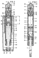
- the length-adjustable gas spring shown in the drawings 1 to 5 has a substantially cylindrical housing 1. It consists of a concentric with the central longitudinal axis 2 arranged outer cylinder 3 and also concentrically arranged in this inner cylinder 4, the radial distance from each other, so that between them a Annular space 5 is formed.
- a piston 6 is displaceable arranged, which is attached to one end of a piston rod 7.
- the piston 6 is by means of a seal 8 against the inner wall 9 of the Inner cylinder 4 sealed.
- the piston rod 7 is from one end of the Housing 1 led out of this. It is for this purpose in a seal-guide unit 10 out, the housing 1 on the piston rod exit gas-tight and the piston rod 7 concentric to the axis 2 leads.
- the piston 6 divides the interior of the inner cylinder 4 into two part-housing spaces 11, 12.
- the between the piston 6 and the seal guide unit 10 formed part-housing space 11 is by means of at least an overflow opening 13 is constantly connected to the annular space 5.
- valve 14 At the opposite end of the piston rod is a valve 14 is provided, by means of which between the piston 6 and the valve 14 formed part-housing space 12 via the annular space 5, the overflow 13 with the other part-housing space 11 and vice versa can be connected.
- the valve 14 has a valve body 15 which the inner cylinder 4 is centered relative to the outer cylinder 13, the part-housing space 12 to the annular space 5 seals, the inner cylinder 4 in the direction determines the axis 2 and the housing 1 gas-tight seals to the outside.
- a concentric recess 16 is arranged, in a valve actuating pin 17 is disposed outwardly of the Valve body 15 protrudes.
- the annular space 5 is constantly by means of a transfer port 18 connected to the recess.
- a transfer port 18 connected to the recess.
- FIG. 2 The essential application of the gas spring is shown in Figure 2.
- a length-adjustable chair column shown having a standpipe 23, in which a guide bushing leading the housing 1 of the gas spring 24 is formed concentrically to the axis 2.
- the outside of the housing 1 located free end of the piston rod 7 is via a pivot bearing 25 a bottom 26 of the standpipe 23 and supported by an opening 27th in the bottom 26 passed through this.
- At the bottom is she attached by means of a securing bracket 28.
- the standpipe 23 then points to the bottom 26 a cone portion 29 which in a corresponding Hub of a pedestal of a chair is used.
- Which conically tapered mounting portion 19 of the gas spring is in a the bottom of the seat of a chair located recording used.
- the Actuation of the actuating pin 17 via the slide 22 by means of a mounted on the underside of the chair seat linkage. This is in the practice widely known and widely used.
- a device 30 is provided, which prevents the piston rod over a predetermined distance a of the piston 6 from the valve 14 also into the Housing 1 is driven.
- a device 30 is thus ensured that the part housing space 12 at least a predetermined length a has, so that the gas spring 14 even when the valve is closed Has seat-suspension characteristics.
- the device 30th of two floating in the inner cylinder 4 floating piston 31, 32, between which a soft coil spring 33 is arranged, respectively is snapped onto a collar 34 of the floating piston 31, 32.
- the Floating piston 31, 32 have against the inner wall 9 of the inner cylinder 4 game so much that a not recognizable in the drawing flow channel 35 is formed so that compressed gas from one side of each Floating piston 31, 32 can pass on the other side.
- the valve 14 facing floating piston 31 has on his the Valve body 15 side facing an annular groove 36, in which a ring seal 37 is arranged, in the unloaded state on the Floating piston 31 protrudes. It is arranged concentrically to the axis 2. Their diameter is greater than that of the recess 16 at the exit in the Partial housing room 12.
- valve 14 If starting from the position shown in Figure 1 with completely off the housing 1 extended piston rod 7, the valve 14 is opened, then the piston rod against the above-mentioned corresponding Counterforce can be inserted into the housing 1, because the conditions just as if the device 30 were not present.
- the ring seal 37 When in the position of the floating piston 31 shown in Figure 2 for conditioning comes on the valve body 15, then the ring seal 37 is tight against the her facing as a sealing surface 38 serving surface of the valve body 15th at.
- a free space 39 is formed in the Valve actuating pin 17 may occur when opening the valve 14, without that the floating piston 31 is lifted from the sealing surface 38.
- the device 30 'differs. only by the means 30 that the voltage applied to the piston 6 Floating piston 32 is omitted; the coil spring 33 is supported directly against the piston 6 from.
- the device 30 is substantially from a foam spring 40, which consists of a cylindrical Foam block of open-cell foam, for example open-cell foam Polyurethane foam, consists. It is a so-called Integral foam, at least on its valve 14 facing circular surface with a so-called casting skin, d. H. one air-impermeable, but elastic layer 41 is provided in the Plant the spring 40 against the sealing surface 38 of the valve body 15 tight abuts against this and the described gas outlet from the valve 14 in the Part housing space 12 and vice versa prevents.
- the spring 40 has a a flow channel 42 forming game against the inner wall. 9 of the inner cylinder 4, so that the gas past the layer 41 into the cells the foam spring 40 can pass and vice versa.
- valve actuating pin 17th arranged such sunk in the valve body 15 that the actuating pin 17th when opening the valve 14 is not from the valve body 15 in the part-housing space 12 enters.
- an open-cell foam can also be a corresponding open-cell rubber as a material of the spring 40 are used.
- the device 30 '' ' is made a closed rubber bellows spring 43, which also has a one Through-channel 44 forming game against the inner wall 9 of the inner cylinder 4 is arranged. It is at the ends with a finishing plate 45, from which an annular sealing web 46 in the direction of Valve body 15 protrudes.
- This ring seal web 46 comes when inserted of the piston 6 in the housing 1 in the manner described for Appendix on the sealing surface 38 and the valve 14 is inoperative.
- outstanding part of the Valve actuating pin 17 is here in the inside of the web 46 free space 47.
- the described device 30, 30 ', 30' ', 30' '' may of course also in length-adjustable single-pipe gas springs are used, in which the Valve is arranged in the piston and arranged by a piston rod in the Actuator is operated from the outside.
- Such length-adjustable Gas springs are in adjustable chair columns in the Used way that the piston rod is led up and wearing the seat.
- adjustable gas springs are in large Scope known.
- the device is located 30, 30 ', 30' ', 30' '' in the part-housing space between the Valve-carrying piston and the lower closed end of the housing, So also not in the penetrated by the piston rod part-housing space.
Landscapes
- Engineering & Computer Science (AREA)
- General Engineering & Computer Science (AREA)
- Mechanical Engineering (AREA)
- Fluid-Damping Devices (AREA)
- Chairs Characterized By Structure (AREA)
- Closing And Opening Devices For Wings, And Checks For Wings (AREA)
Description
- Fig. 1
- eine längenverstellbare Gasfeder im Längsschnitt mit einer ersten Einrichtung zum Verschließen des Ventils in einer vorgegebenen Einschubstellung der Kolbenstange,
- Fig. 2
- die Gasfeder nach Figur 1 in in ein Standrohr eingebautem Zustand, ebenfalls im Längsschnitt,
- Fig. 3
- eine längenverstellbare Gasfeder mit einer zweiten Einrichtung,
- Fig. 4
- eine längenverstellbare Gasfeder mit einer dritten Einrichtung und
- Fig. 5
- eine längenverstellbare Gasfeder mit einer vierten Einrichtung.
Claims (6)
- Längenverstellbare Gasfeder
mit einem Gehäuse (1) mit einer Mittel-Längs-Achse (2),
mit einer aus dem Gehäuse (1) konzentrisch zur Mittel-Längs-Achse (2) herausgeführten Kolbenstange (7),
mit einem an der Kolbenstange (7) angebrachten, im Gehäuse (1) verschiebbaren, das Gehäuse (1) in einen ersten Teil-Gehäuseraum (11) und einen zweiten Teil-Gehäuseraum (12) aufteilenden Kolben (6), wobei die Kolbenstange (7) den ersten Teil-Gehäuseraum (11) durchsetzt, und
mit einem Ventil (14) zum Verbinden der Teil-Gehäuseräume (11, 12) miteinander,
wobei im zweiten Teil-Gehäuseraum (12) eine Einrichtung (30, 30', 30", 30''') zum Verschließen des Ventils (14) angeordnet ist, die das Ventil (14) bei Erreichen einer vorgegebenen Mindest-Länge (a) des zweiten Teil-Gehäuseraums (12) verschließt, dadurch gekennzeichnet, dass die Einrichtung (30, 30', 30", 30''') eine weiche Feder (30, 40, 43) mit einer bei Erreichen der vorgegebenen Mindest-Länge (a) des zweiten Teil-Gehäuseraums (12) an einer Dichtfläche (38) des Ventils (14) elastisch dichtend zur Anlage kommenden Dichtung (37, 41, 46) aufweist. - Gasfeder nach Anspruch 1, dadurch gekennzeichnet, daß die Feder als Schraubenfeder (33) ausgebildet ist, die mindestens an ihrer dem Ventil (14) zugewandten Seite mit einem Schwimm-Kolben (31) versehen ist, der eine der Dichtfläche (38) des Ventils (14) zugewandte und zugeordnete Ringdichtung (37) aufweist.
- Gasfeder nach Anspruch 1, dadurch gekennzeichnet, daß die Feder als Gummi-Balg-Feder (43) ausgebildet ist.
- Gasfeder nach Anspruch 3, dadurch gekennzeichnet, daß die Gummi-Balg-Feder (43) mindestens an ihrer dem Ventil (14) zugewandten Seite mit einem Ringdichtungs-Steg (46) zur Anlage an der Dichtfläche (38) des Ventils (14) versehen ist.
- Gasfeder nach Anspruch 1, dadurch gekennzeichnet, daß die Feder als offenzellige Schaumstoff-Feder (40) ausgebildet ist.
- Gasfeder nach Anspruch 5, dadurch gekennzeichnet, daß die Schaumstoff-Feder (40) auf ihrer dem Ventil (14) zugewandten Seite mit einer gasdichten elastischen Schicht (41) zur Anlage an der Dichtfläche (38) des Ventils (14) versehen ist.
Applications Claiming Priority (2)
| Application Number | Priority Date | Filing Date | Title |
|---|---|---|---|
| DE19827657A DE19827657A1 (de) | 1998-06-22 | 1998-06-22 | Längenverstellbare Gasfeder |
| DE19827657 | 1998-06-22 |
Publications (3)
| Publication Number | Publication Date |
|---|---|
| EP0967408A2 EP0967408A2 (de) | 1999-12-29 |
| EP0967408A3 EP0967408A3 (de) | 2003-01-08 |
| EP0967408B1 true EP0967408B1 (de) | 2005-08-24 |
Family
ID=7871591
Family Applications (1)
| Application Number | Title | Priority Date | Filing Date |
|---|---|---|---|
| EP99110529A Expired - Lifetime EP0967408B1 (de) | 1998-06-22 | 1999-06-01 | Längenverstellbare Gasfeder |
Country Status (7)
| Country | Link |
|---|---|
| US (1) | US6234461B1 (de) |
| EP (1) | EP0967408B1 (de) |
| JP (1) | JP2000035074A (de) |
| KR (1) | KR200394265Y1 (de) |
| DE (2) | DE19827657A1 (de) |
| ES (1) | ES2247747T3 (de) |
| TW (1) | TW456478U (de) |
Families Citing this family (33)
| Publication number | Priority date | Publication date | Assignee | Title |
|---|---|---|---|---|
| US7070028B2 (en) * | 2001-02-07 | 2006-07-04 | Tenneco Automotive Operating Company Inc. | Frequency dependent damper |
| US6446943B1 (en) * | 2001-02-07 | 2002-09-10 | Strongarm Designs, Inc. | Gas spring pressure release mechanism |
| DE10148430C2 (de) * | 2001-10-01 | 2003-08-14 | Stabilus Gmbh | Blockierbares Kolben-Zylinderaggregat |
| DE10222940C1 (de) * | 2002-05-24 | 2003-07-31 | Zf Sachs Ag | Schwingungsdämpfer mit einem hydraulischen Druckanschlag |
| US8464850B2 (en) | 2006-11-16 | 2013-06-18 | Fox Factory, Inc. | Gas spring curve control in an adjustable-volume gas-pressurized device |
| US20080296814A1 (en) | 2002-06-25 | 2008-12-04 | Joseph Franklin | Gas spring with travel control |
| US7703585B2 (en) | 2002-06-25 | 2010-04-27 | Fox Factory, Inc. | Integrated and self-contained suspension assembly having an on-the-fly adjustable air spring |
| US10941828B2 (en) | 2002-06-25 | 2021-03-09 | Fox Factory, Inc. | Gas spring with travel control |
| US20040007607A1 (en) * | 2002-07-12 | 2004-01-15 | Daniels Mark E. | Roll mounted bags and dispensers for same |
| US7963509B2 (en) | 2007-01-31 | 2011-06-21 | Fox Factory, Inc. | Travel control for a gas spring and gas spring having very short travel modes |
| DE10316912B3 (de) * | 2003-04-12 | 2004-10-21 | Stabilus Gmbh | Gasfeder |
| DE10329468B3 (de) * | 2003-07-01 | 2004-11-18 | Stabilus Gmbh | Gasfeder |
| DE102004023335A1 (de) * | 2004-01-24 | 2005-08-11 | Suspa Holding Gmbh | Höhenverstellbare Stuhl-Säule |
| KR200348804Y1 (ko) * | 2004-02-05 | 2004-04-29 | 주식회사 한국가스스프링 | 가스 실린더용 밸브의 조립 구조물 |
| DE102004034942A1 (de) * | 2004-07-20 | 2006-03-16 | Volkswagen Ag | Schwingungsdämpfer mit einem Zuganschlag |
| US20060090973A1 (en) * | 2004-10-28 | 2006-05-04 | Michael Potas | Valve system controlled by rate of pressure change |
| CN1333182C (zh) * | 2005-04-22 | 2007-08-22 | 清华大学 | 可调节刚度和阻尼的空气弹簧隔振器 |
| US7921974B2 (en) * | 2005-11-29 | 2011-04-12 | Fox Factory, Inc. | Damping cylinder with annular bladder |
| US8162112B2 (en) | 2007-02-09 | 2012-04-24 | Competition Tire East | Methods and apparatus for protecting a shock absorber from bottoming |
| US8123006B1 (en) * | 2007-04-13 | 2012-02-28 | Hayes Bicycle Group, Inc. | Lightweight gas spring design with volume compensator incorporated into a suspension fork for two wheeled vehicles |
| US20080284073A1 (en) * | 2007-05-16 | 2008-11-20 | Heleski Clare P | Variable speed gas spring |
| US8123203B2 (en) * | 2009-02-25 | 2012-02-28 | GM Global Technology Operations LLC | Vehicular jounce bumper assembly |
| KR101035016B1 (ko) * | 2009-05-12 | 2011-05-17 | 주식회사 한국가스스프링 | 속도 제어용 가스 스프링 |
| US8240642B2 (en) * | 2010-02-12 | 2012-08-14 | Bwi Company Limited S.A. | Fluid damper with internal compression spring |
| US9193241B2 (en) | 2013-02-28 | 2015-11-24 | GM Global Technology Operations LLC | Systems and methods for damper having jounce shock |
| AU2014352753B2 (en) * | 2013-11-21 | 2018-11-01 | Stabilus, Inc. | Systems and methods for piston assemblies |
| US9186948B2 (en) | 2013-12-06 | 2015-11-17 | GM Global Technology Operations LLC | Systems and methods for damper having an insert |
| KR101516808B1 (ko) * | 2013-12-13 | 2015-05-04 | 주식회사 삼홍사 | 가스 실린더 |
| KR101631641B1 (ko) * | 2015-01-19 | 2016-06-20 | 주식회사 삼홍사 | 가스 실린더 |
| US10399402B2 (en) * | 2016-06-30 | 2019-09-03 | Beijingwest Industries Co., Ltd. | Strut assembly including a bearing sleeve having a radial protrusion |
| CN108869618A (zh) * | 2018-08-14 | 2018-11-23 | 江苏睿博工业科技有限公司 | 多级同步自锁气弹簧 |
| CN111536745A (zh) * | 2020-05-06 | 2020-08-14 | 长虹美菱股份有限公司 | 一种搁架升降装置及应用其的冰箱 |
| WO2022153067A1 (en) * | 2021-01-18 | 2022-07-21 | Carbon Air Limited | Air spring |
Family Cites Families (15)
| Publication number | Priority date | Publication date | Assignee | Title |
|---|---|---|---|---|
| US2729308A (en) * | 1952-01-05 | 1956-01-03 | Gabriel Co | Multiple stage shock absorber |
| DE1430494B1 (de) * | 1962-01-22 | 1970-04-02 | Carbon Christian Marie Lucien | Hydropneumatischer Einrohr-Stossdaempfer fuer Kraftfahrzeuge |
| DE1226833B (de) * | 1963-06-07 | 1966-10-13 | Zschopau Motorrad Veb | Hydraulischer Teleskopstossdaempfer |
| DE1775090A1 (de) * | 1967-07-11 | 1972-04-13 | Piero Montanari | Teleskopartiger hydropneumatischer Stossdaempfer |
| DE1812282C3 (de) * | 1968-12-03 | 1981-07-30 | Fritz Bauer + Söhne oHG, 8503 Altdorf | Hubvorrichtung zum stufenlosen Höhenverstellen von Tischplatten, Stuhlsitzen u.dgl. |
| DE2907100A1 (de) | 1979-02-23 | 1980-08-28 | Bauer Fritz & Soehne Ohg | Laengenverstellbare gasfeder |
| DE2942455A1 (de) * | 1979-10-20 | 1981-04-30 | Fritz Bauer + Söhne oHG, 8503 Altdorf | Laengenverstellbare gasfeder |
| DE3533387A1 (de) * | 1985-09-19 | 1987-03-26 | Fichtel & Sachs Ag | Zweirohr-schwingungsdaempfer mit hydraulischem druckanschlag |
| DE3533386C2 (de) * | 1985-09-19 | 1994-05-11 | Fichtel & Sachs Ag | Zweirohrschwingungsdämpfer mit federbeaufschlagtem, hydraulischem Druckanschlag |
| US4880213A (en) * | 1986-01-30 | 1989-11-14 | Nhk Spring Co., Ltd. | Gas spring apparatus |
| GB2186050B (en) * | 1986-01-30 | 1989-10-25 | Nhk Spring Co Ltd | Car suspension system |
| US4890822A (en) * | 1986-02-13 | 1990-01-02 | Nhk Spring Co., Ltd. | Car suspension system |
| DE4000865A1 (de) * | 1990-01-13 | 1991-07-18 | Stabilus Gmbh | Gasfeder mit zwischenarretierung |
| US5511759A (en) * | 1994-05-26 | 1996-04-30 | Steelcase, Inc. | Hydraulic chair height adjustment mechanism |
| DE19604962A1 (de) * | 1996-02-10 | 1997-08-14 | Suspa Compart Ag | Längenverstellbare Gasfeder |
-
1998
- 1998-06-22 DE DE19827657A patent/DE19827657A1/de not_active Withdrawn
-
1999
- 1999-06-01 ES ES99110529T patent/ES2247747T3/es not_active Expired - Lifetime
- 1999-06-01 EP EP99110529A patent/EP0967408B1/de not_active Expired - Lifetime
- 1999-06-01 DE DE59912451T patent/DE59912451D1/de not_active Expired - Lifetime
- 1999-06-10 TW TW088209559U patent/TW456478U/zh not_active IP Right Cessation
- 1999-06-21 KR KR20-1999-0010999U patent/KR200394265Y1/ko not_active Expired - Lifetime
- 1999-06-21 JP JP11174350A patent/JP2000035074A/ja active Pending
- 1999-06-22 US US09/337,256 patent/US6234461B1/en not_active Expired - Lifetime
Also Published As
| Publication number | Publication date |
|---|---|
| EP0967408A2 (de) | 1999-12-29 |
| KR200394265Y1 (ko) | 2005-08-31 |
| TW456478U (en) | 2001-09-21 |
| US6234461B1 (en) | 2001-05-22 |
| ES2247747T3 (es) | 2006-03-01 |
| DE19827657A1 (de) | 1999-12-23 |
| JP2000035074A (ja) | 2000-02-02 |
| DE59912451D1 (de) | 2005-09-29 |
| KR20000002173U (ko) | 2000-01-25 |
| EP0967408A3 (de) | 2003-01-08 |
Similar Documents
| Publication | Publication Date | Title |
|---|---|---|
| EP0967408A2 (de) | Längenverstellbare Gasfeder | |
| DE69310261T2 (de) | Proportionales, elektromagnetisch gesteuertes Ventil | |
| DE69418902T2 (de) | Regel- und modulierbare hydropneumatische dämpfungsvorrichtung | |
| EP0872674B1 (de) | Druckausgeglichenes Magnetventil | |
| DE3738298C2 (de) | Längenverstellbare Gasfeder für höhenverstellbare Stühle | |
| EP2167820B1 (de) | Membranpumpe | |
| DE2341352C2 (de) | Blockierbares Hubaggregat mit Endfederung | |
| DE102010002937B3 (de) | Schwingungsdämpfer mit hubabhängiger Dämpfkraft | |
| DE4024920A1 (de) | Schwingungsdaempfer | |
| DE19810391A1 (de) | Druckreduzierventil | |
| WO2001055602A1 (de) | Hydropneumatischer druckspeicher | |
| DE3008707A1 (de) | Kolben mit druckabhaengiger anpressung des kolbenringes an die zylinderinnenwand | |
| DE3534692C2 (de) | ||
| DE3819392A1 (de) | Durch fluiddruck ausfahrbare und durch federbelastung zurueckziehbare anordnung | |
| DE69007406T2 (de) | Kolben für Druckzylinder. | |
| EP1557114B1 (de) | Höhenverstellbare Stuhl-Säule | |
| DE3630757C2 (de) | ||
| DE3629569C1 (de) | Sanitaeres Ventil | |
| CH665940A5 (de) | Verstellvorrichtung, insbesondere fuer neigbare und hoehenverstellbare stuehle. | |
| DE4404467A1 (de) | Türfeststeller für Türen | |
| DE3838765A1 (de) | Sanitaeres wasserventil mit betaetigungsmechanik | |
| DE2848128C2 (de) | Kondensatableiter | |
| DE2206827A1 (de) | Regelventil mit doppeltem Sitz | |
| DE69012412T2 (de) | Positionier-Einrichtung. | |
| DE2716831A1 (de) | Mischventil |
Legal Events
| Date | Code | Title | Description |
|---|---|---|---|
| PUAI | Public reference made under article 153(3) epc to a published international application that has entered the european phase |
Free format text: ORIGINAL CODE: 0009012 |
|
| AK | Designated contracting states |
Kind code of ref document: A2 Designated state(s): AT BE CH CY DE DK ES FI FR GB GR IE IT LI LU MC NL PT SE |
|
| AX | Request for extension of the european patent |
Free format text: AL;LT;LV;MK;RO;SI |
|
| RAP1 | Party data changed (applicant data changed or rights of an application transferred) |
Owner name: SUSPA HOLDING GMBH |
|
| PUAL | Search report despatched |
Free format text: ORIGINAL CODE: 0009013 |
|
| AK | Designated contracting states |
Kind code of ref document: A3 Designated state(s): AT BE CH CY DE DK ES FI FR GB GR IE IT LI LU MC NL PT SE |
|
| AX | Request for extension of the european patent |
Free format text: AL;LT;LV;MK;RO;SI |
|
| RIC1 | Information provided on ipc code assigned before grant |
Free format text: 7F 16F 9/02 A, 7F 16F 9/48 B |
|
| RAP1 | Party data changed (applicant data changed or rights of an application transferred) |
Owner name: SUSPA COMPART GMBH |
|
| 17P | Request for examination filed |
Effective date: 20030121 |
|
| AKX | Designation fees paid |
Designated state(s): DE ES FR GB IT |
|
| RAP1 | Party data changed (applicant data changed or rights of an application transferred) |
Owner name: SUSPA HOLDING GMBH |
|
| GRAP | Despatch of communication of intention to grant a patent |
Free format text: ORIGINAL CODE: EPIDOSNIGR1 |
|
| GRAS | Grant fee paid |
Free format text: ORIGINAL CODE: EPIDOSNIGR3 |
|
| GRAA | (expected) grant |
Free format text: ORIGINAL CODE: 0009210 |
|
| AK | Designated contracting states |
Kind code of ref document: B1 Designated state(s): DE ES FR GB IT |
|
| REG | Reference to a national code |
Ref country code: GB Ref legal event code: FG4D Free format text: NOT ENGLISH |
|
| GBT | Gb: translation of ep patent filed (gb section 77(6)(a)/1977) |
Effective date: 20050824 |
|
| REF | Corresponds to: |
Ref document number: 59912451 Country of ref document: DE Date of ref document: 20050929 Kind code of ref document: P |
|
| REG | Reference to a national code |
Ref country code: ES Ref legal event code: FG2A Ref document number: 2247747 Country of ref document: ES Kind code of ref document: T3 |
|
| ET | Fr: translation filed | ||
| PLBE | No opposition filed within time limit |
Free format text: ORIGINAL CODE: 0009261 |
|
| STAA | Information on the status of an ep patent application or granted ep patent |
Free format text: STATUS: NO OPPOSITION FILED WITHIN TIME LIMIT |
|
| 26N | No opposition filed |
Effective date: 20060526 |
|
| PGFP | Annual fee paid to national office [announced via postgrant information from national office to epo] |
Ref country code: ES Payment date: 20080625 Year of fee payment: 10 |
|
| PGFP | Annual fee paid to national office [announced via postgrant information from national office to epo] |
Ref country code: IT Payment date: 20080625 Year of fee payment: 10 |
|
| PGFP | Annual fee paid to national office [announced via postgrant information from national office to epo] |
Ref country code: GB Payment date: 20080624 Year of fee payment: 10 |
|
| REG | Reference to a national code |
Ref country code: FR Ref legal event code: TP |
|
| GBPC | Gb: european patent ceased through non-payment of renewal fee |
Effective date: 20090601 |
|
| PG25 | Lapsed in a contracting state [announced via postgrant information from national office to epo] |
Ref country code: GB Free format text: LAPSE BECAUSE OF NON-PAYMENT OF DUE FEES Effective date: 20090601 |
|
| REG | Reference to a national code |
Ref country code: ES Ref legal event code: FD2A Effective date: 20090602 |
|
| PG25 | Lapsed in a contracting state [announced via postgrant information from national office to epo] |
Ref country code: ES Free format text: LAPSE BECAUSE OF NON-PAYMENT OF DUE FEES Effective date: 20090602 |
|
| PG25 | Lapsed in a contracting state [announced via postgrant information from national office to epo] |
Ref country code: IT Free format text: LAPSE BECAUSE OF NON-PAYMENT OF DUE FEES Effective date: 20090601 |
|
| REG | Reference to a national code |
Ref country code: FR Ref legal event code: PLFP Year of fee payment: 18 |
|
| REG | Reference to a national code |
Ref country code: FR Ref legal event code: PLFP Year of fee payment: 19 |
|
| REG | Reference to a national code |
Ref country code: FR Ref legal event code: PLFP Year of fee payment: 20 |
|
| PGFP | Annual fee paid to national office [announced via postgrant information from national office to epo] |
Ref country code: DE Payment date: 20180630 Year of fee payment: 20 |
|
| PGFP | Annual fee paid to national office [announced via postgrant information from national office to epo] |
Ref country code: FR Payment date: 20180620 Year of fee payment: 20 |
|
| REG | Reference to a national code |
Ref country code: DE Ref legal event code: R071 Ref document number: 59912451 Country of ref document: DE |