EP0967416A1 - Rolle zum Führen und/oder Spannen eines Treibriemens - Google Patents
Rolle zum Führen und/oder Spannen eines Treibriemens Download PDFInfo
- Publication number
- EP0967416A1 EP0967416A1 EP99401601A EP99401601A EP0967416A1 EP 0967416 A1 EP0967416 A1 EP 0967416A1 EP 99401601 A EP99401601 A EP 99401601A EP 99401601 A EP99401601 A EP 99401601A EP 0967416 A1 EP0967416 A1 EP 0967416A1
- Authority
- EP
- European Patent Office
- Prior art keywords
- discs
- roller
- belt
- roller according
- offset
- Prior art date
- Legal status (The legal status is an assumption and is not a legal conclusion. Google has not performed a legal analysis and makes no representation as to the accuracy of the status listed.)
- Granted
Links
- 230000005540 biological transmission Effects 0.000 title claims abstract description 7
- 230000002093 peripheral effect Effects 0.000 claims abstract description 13
- 238000010586 diagram Methods 0.000 description 3
- 238000009826 distribution Methods 0.000 description 3
- 230000002787 reinforcement Effects 0.000 description 3
- 230000008901 benefit Effects 0.000 description 2
- 230000008859 change Effects 0.000 description 2
- 238000002485 combustion reaction Methods 0.000 description 2
- 230000004048 modification Effects 0.000 description 2
- 238000012986 modification Methods 0.000 description 2
- 230000009467 reduction Effects 0.000 description 2
- 208000031968 Cadaver Diseases 0.000 description 1
- 239000011324 bead Substances 0.000 description 1
- 230000003542 behavioural effect Effects 0.000 description 1
- 210000004027 cell Anatomy 0.000 description 1
- 230000000295 complement effect Effects 0.000 description 1
- 230000007423 decrease Effects 0.000 description 1
- 230000000694 effects Effects 0.000 description 1
- 229940082150 encore Drugs 0.000 description 1
- 230000001939 inductive effect Effects 0.000 description 1
- 230000001788 irregular Effects 0.000 description 1
- 238000003754 machining Methods 0.000 description 1
- 238000004519 manufacturing process Methods 0.000 description 1
- 238000000034 method Methods 0.000 description 1
- 238000000465 moulding Methods 0.000 description 1
- 230000010355 oscillation Effects 0.000 description 1
- 244000045947 parasite Species 0.000 description 1
- 230000002028 premature Effects 0.000 description 1
- 230000008569 process Effects 0.000 description 1
Images

Classifications
-
- F—MECHANICAL ENGINEERING; LIGHTING; HEATING; WEAPONS; BLASTING
- F16—ENGINEERING ELEMENTS AND UNITS; GENERAL MEASURES FOR PRODUCING AND MAINTAINING EFFECTIVE FUNCTIONING OF MACHINES OR INSTALLATIONS; THERMAL INSULATION IN GENERAL
- F16H—GEARING
- F16H7/00—Gearings for conveying rotary motion by endless flexible members
- F16H7/18—Means for guiding or supporting belts, ropes, or chains
-
- F—MECHANICAL ENGINEERING; LIGHTING; HEATING; WEAPONS; BLASTING
- F16—ENGINEERING ELEMENTS AND UNITS; GENERAL MEASURES FOR PRODUCING AND MAINTAINING EFFECTIVE FUNCTIONING OF MACHINES OR INSTALLATIONS; THERMAL INSULATION IN GENERAL
- F16H—GEARING
- F16H57/00—General details of gearing
- F16H57/0006—Vibration-damping or noise reducing means specially adapted for gearings
Definitions
- the present invention relates to a roller for guiding and / or the tension of a transmission belt.
- the invention relates more particularly to a roller intended to be placed in the path of a toothed belt for rotational drive of components and equipment of a motor vehicle engine.
- the toothed belt is driven by a pinion associated with the engine crankshaft and it drives for example at least one camshaft per at least one camshaft sprocket.
- the belt tension which can be adjustable, is provided by at least one tensioner roller which cooperates with the back of the toothed belt, the path of the belt being able also include at least one roller of the same type.
- the body of the roller is mounted rotating, that is to say crazy in rotation, and the peripheral surface of generally cylindrical shape or tapered body of the roller is in contact with the back, or back, smooth belt.
- Another set of solutions is to modify the shape of the peripheral surface, or track, of the pebbles contact with the back of the strap.
- the runway of the roller has at least one peripheral section bead of variable shape and height.
- the pebble track should include evenly distributed surface sections or irregular, angularly around the axis of rotation of the roller, these sections being more important than the number of teeth of the toothed belt at the periphery of the track.
- the track is not cylindrical or purely frustoconical and has for example, in cross section, a curvature concave in particular in the shape of a V groove.
- the invention offers a roller of the type mentioned above, characterized in that the peripheral surface of the body of the roller is wavy in the axial direction.
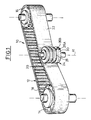
- FIG. 1 shows a transmission 10 comprising a toothed belt 12 which is for example driven in rotation by a pinion 14 which is driven in rotation by the crankshaft (not shown) of a combustion of a motor vehicle.
- the belt 12 transmits the force applied to it by the pinion 14 to a receiving pinion 16 which is for example a camshaft gear (not shown).
- the pinions 14 and 16 are of axes of rotation substantially parallel.
- the toothed belt 12 is present in the form of a continuous thick strip substantially constant with the internal or front side 18 has a series of teeth 20 to constitute the internal face notched belt 12 which cooperates with complementary teeth pinions 14 and 16.
- the back or reverse side 22 of the toothed belt 12 is present as a continuous strip on the surface noticeably smooth.
- tensioner 24 which is mounted for rotation about an axis A1 substantially parallel to the axes of rotation of the pinions 14 and 16.
- the roller 24 is constituted by a stack of adjacent discs 26i of which, as will be explained by the continued, the diameters are different and / or the axes are offset, so that the peripheral surface, or outer casing, of the roller 24 which is in contact with the back 22 of the belt 12 is wavy in the axial direction, i.e. has a series of depressions 28i and projections 30i if we consider this peripheral surface in moving transversely, i.e. in one direction parallel to the rotation axis A1 of the roller 24.
- the roller 24 is constituted by a stack of nine adjacent discs.
- the nine discs include five 26A large diameter discs and four small discs diameter 26B which are inserted between the large discs diameter 26A.
- the nine disks are axis coaxial common with axis of rotation A1.
- peripheral surface or outer envelope the body of the roller 24 is constituted by an alternation regular projections formed by cylindrical tracks external 28A large diameter discs and depression 30B constituted by the cylindrical tracks outside of small diameter discs 26B.
- the disks 26A and 26B are shown as having all substantially the same axial thickness.
- each disc preferably being at least equal to the diameter one of the cables or ropes which, in a known manner, longitudinally reinforce the main band or heel constant thickness of the belt.
- the invention is not limited either to the stacking of two sets of discs of different diameters, the body of the roller 24 which may consist of a stack of one more large number of sets of discs, each set of one determined diameter preferably comprising disks of same axial thickness.
- the alternate arrangement of discs of diameters different belonging to two sets of discs allows advantageously to prevent lateral sliding of the back 22 of the belt 12 on the roller 24 when the diameter of the discs increases and decreases alternately along of a cross section of the stack.
- the arrangement creates a local offset of the vibrations of the reinforcement cables or ropes in the strands of the belt which are in contact with the outer cylindrical track or surface of the roller, this offset reducing the amplitude of oscillation of the strands when they undergo a phenomenon of resonance.
- Variable offset of vibrations of cables or ropes can be obtained by making complex variations of the number of sets of disc diameter along the width transverse of the roller.
- the difference in diameters between the discs belonging to the two disc series 26A and 26B of the mode of embodiment illustrated in FIGS. 1 and 2 can in particular be chosen according to the thickness of the main part continues in the form of a band of the belt, i.e. the thickness separating surfaces 18 and 22 taking into account possibly or not the diameter of the cables or ropes of reinforcement.
- the body of the roller 24 is here too consisting of a stack of nine adjacent discs.
- This stack consists of discs belonging to two sets of discs, i.e. 26A discs more large diameter and 26B small diameter discs.
- the four large diameter 26A discs are all coaxials having as common axis the axis A1 of rotation of the roller 24.
- the radial eccentricity of the axis of each of the discs of small diameter 26Bi is here equal and, as we can see more clearly on the diagram of figure 6, the position of the axis of rotation ABi of each small diameter disc 26Bi relative to the general axis of rotation A1 is angularly offset 90 ° around the A1 axis.
- the geometric axis AB2 of the second disc of small diameter 26B2 (considering the stack in Figure 4 from top to bottom) is angularly offset by 90 ° to the geometric axis AB1 of the first small diameter disc 26B1 and this counterclockwise considering the diagram of figure 6.
- This angular offset is successively the same for the four 26Bi small diameter discs stacked vertically from top to bottom, with interposition each time a large diameter disc 26A.
- the arrangement of discs stacked with offset allows to impose an overall ripple on the cables or belt reinforcement ropes whose backs are in contact with the roller 24. This undulation promotes an induced modification vibratory conditions of the belt strands in prohibiting the establishment of the main beat modes of these strands.
- the diameter of this class is called the primitive diameter of discs, i.e. the diameter of discs of large diameter 26A considering the example in Figure 4.
- the 26Bi discs belonging to the other series of discs, which are here the discs of smaller diameter have a eccentricity in a varying radial direction, like this has been explained, depending on the axial position of the disc in stacking.
- the offset can be applied to small diameter discs or larger diameter.
- the overall ripple applied can be obtained by performing an offset which varies in value as a function of the angular portion of the axis of the eccentric disc with respect to the general axis of rotation A1 and according to the axial position of the disc in the stack.
- the invention is not limited to a value constant offset for each of the offset discs.
- the value of the offset is arbitrarily chosen to be a constant value substantially equal to half the thickness constant of the main strap of the belt 12.
- each disc has a circular cylindrical outer track.
- cams forms, which are not of revolution, called cams.
- a cam as the assembly, at same width, the volume of a disc with a primitive diameter (previously defined) with at least one shaped disc general ellipsoidal or round, whose eccentricities respective may vary.
- Each thin cam can be of the type simple, that is to say comprising a single maximum of radius, or complex, i.e. comprising several maximums of Ray.
- the ripple overall apparent of the outer surface track roller device 24 can be obtained by varying the parameters of thickness and dimension of the cams as well that their respective eccentricities, in particular by retaining the benefit of preventing the side slip effect untimely belt relative to the roller.
- the invention is also not limited to the realization of the roller by a stack of adjacent discs, the surface overall wavy track of the pebble which can be obtained by any other means, in particular by molding and / or machining.
- each stacking element and more particularly of those constituting the projections 28, can present in section rounded edges in order to reduce risk of premature wear of the back 22 of the belt 12 due to lateral sliding of the latter relative to the roller.
- roller 24 is used as a tensioner roller or guide roller of a toothed belt
- roller according to the invention can be used with any type of belt drive kept under tension.
- the discs can be of curved profile according to the direction axial A1 or else they may have rounded edges.
- peripheral surface of the roller can be general cylindrical, domed or frustoconical shape.
Landscapes
- Engineering & Computer Science (AREA)
- General Engineering & Computer Science (AREA)
- Mechanical Engineering (AREA)
- Devices For Conveying Motion By Means Of Endless Flexible Members (AREA)
Applications Claiming Priority (2)
| Application Number | Priority Date | Filing Date | Title |
|---|---|---|---|
| FR9808122 | 1998-06-26 | ||
| FR9808122A FR2780473B1 (fr) | 1998-06-26 | 1998-06-26 | Galet tendeur de courroie de distribution de moteur a combustion de vehicule automobile |
Publications (2)
| Publication Number | Publication Date |
|---|---|
| EP0967416A1 true EP0967416A1 (de) | 1999-12-29 |
| EP0967416B1 EP0967416B1 (de) | 2003-10-29 |
Family
ID=9527902
Family Applications (1)
| Application Number | Title | Priority Date | Filing Date |
|---|---|---|---|
| EP19990401601 Expired - Lifetime EP0967416B1 (de) | 1998-06-26 | 1999-06-25 | Rolle zum Führen und/oder Spannen eines Treibriemens |
Country Status (4)
| Country | Link |
|---|---|
| EP (1) | EP0967416B1 (de) |
| DE (1) | DE69912357T2 (de) |
| ES (1) | ES2207142T3 (de) |
| FR (1) | FR2780473B1 (de) |
Cited By (2)
| Publication number | Priority date | Publication date | Assignee | Title |
|---|---|---|---|---|
| FR2838492A1 (fr) * | 2002-04-16 | 2003-10-17 | Renault Sa | Galet enrouleur pour courroie de distribution de moteur a combustion |
| DE102004030287A1 (de) * | 2004-06-23 | 2006-01-12 | Ina-Schaeffler Kg | Umschlingungstrieb für Brennkraftmaschine mit Triebberuhigung |
Families Citing this family (1)
| Publication number | Priority date | Publication date | Assignee | Title |
|---|---|---|---|---|
| DE20208298U1 (de) | 2002-05-28 | 2002-09-05 | Sowka, Maurycy, 33181 Bad Wünnenberg | Rolle für Zugmittel |
Citations (6)
| Publication number | Priority date | Publication date | Assignee | Title |
|---|---|---|---|---|
| GB713557A (en) * | 1951-06-04 | 1954-08-11 | United States Steel Corp | Apparatus for automatically centering a moving object |
| GB1405259A (en) * | 1972-05-19 | 1975-09-10 | English Electric Co Ltd | Wheels and rollers |
| JPH04102755A (ja) * | 1990-08-18 | 1992-04-03 | Toyota Motor Corp | 樹脂製プーリ |
| US5117970A (en) * | 1991-06-19 | 1992-06-02 | Asgco Manufacturing, Inc. | Idler roller sleeve |
| DE4304829A1 (de) * | 1993-02-17 | 1994-08-25 | Schaeffler Waelzlager Kg | Steuertrieb für eine Brennkraftmaschine |
| DE19515351A1 (de) * | 1994-05-04 | 1995-11-09 | Volkswagen Ag | Umlenkrolle |
-
1998
- 1998-06-26 FR FR9808122A patent/FR2780473B1/fr not_active Expired - Fee Related
-
1999
- 1999-06-25 ES ES99401601T patent/ES2207142T3/es not_active Expired - Lifetime
- 1999-06-25 DE DE1999612357 patent/DE69912357T2/de not_active Expired - Lifetime
- 1999-06-25 EP EP19990401601 patent/EP0967416B1/de not_active Expired - Lifetime
Patent Citations (6)
| Publication number | Priority date | Publication date | Assignee | Title |
|---|---|---|---|---|
| GB713557A (en) * | 1951-06-04 | 1954-08-11 | United States Steel Corp | Apparatus for automatically centering a moving object |
| GB1405259A (en) * | 1972-05-19 | 1975-09-10 | English Electric Co Ltd | Wheels and rollers |
| JPH04102755A (ja) * | 1990-08-18 | 1992-04-03 | Toyota Motor Corp | 樹脂製プーリ |
| US5117970A (en) * | 1991-06-19 | 1992-06-02 | Asgco Manufacturing, Inc. | Idler roller sleeve |
| DE4304829A1 (de) * | 1993-02-17 | 1994-08-25 | Schaeffler Waelzlager Kg | Steuertrieb für eine Brennkraftmaschine |
| DE19515351A1 (de) * | 1994-05-04 | 1995-11-09 | Volkswagen Ag | Umlenkrolle |
Non-Patent Citations (1)
| Title |
|---|
| PATENT ABSTRACTS OF JAPAN vol. 016, no. 343 (M - 1285) 24 July 1992 (1992-07-24) * |
Cited By (2)
| Publication number | Priority date | Publication date | Assignee | Title |
|---|---|---|---|---|
| FR2838492A1 (fr) * | 2002-04-16 | 2003-10-17 | Renault Sa | Galet enrouleur pour courroie de distribution de moteur a combustion |
| DE102004030287A1 (de) * | 2004-06-23 | 2006-01-12 | Ina-Schaeffler Kg | Umschlingungstrieb für Brennkraftmaschine mit Triebberuhigung |
Also Published As
| Publication number | Publication date |
|---|---|
| FR2780473A1 (fr) | 1999-12-31 |
| DE69912357T2 (de) | 2004-08-12 |
| DE69912357D1 (de) | 2003-12-04 |
| ES2207142T3 (es) | 2004-05-16 |
| EP0967416B1 (de) | 2003-10-29 |
| FR2780473B1 (fr) | 2000-08-04 |
Similar Documents
| Publication | Publication Date | Title |
|---|---|---|
| EP0202968B1 (de) | Homokinetisches ausziehbares Kreuzgelenk, insbesondere für Fahrzeug-Schräggetriebe | |
| EP0023460B1 (de) | Insbesondere als Fahrzeugrad oder Zahnrad verwendbares verformbares Rad | |
| MC1122A1 (fr) | Engrenage planetaire | |
| FR2593576A1 (fr) | Chaine de transmission de puissance permettant des mouvements de flexion plus larges entre les ensembles de maillons contigus | |
| FR2705941A1 (fr) | Ensemble de pignons pour bicyclettes. | |
| FR2791110A1 (fr) | Dispositif amortisseur d'oscillations a masses de debattement a roulement force | |
| FR2538480A1 (fr) | Perfectionnements apportes aux disques d'embrayage a friction, notamment pour vehicules automobiles | |
| FR2792980A1 (fr) | Joint universel homocinetique plongeant pour arbre de propulsion | |
| FR2801357A1 (fr) | Chaine articulee | |
| EP0022045A1 (de) | Führungsrolle, insbesondere für Geschwindigkeitswechselgetriebe von Fahrrädern und ähnlichen Fahrzeugen | |
| EP0967416B1 (de) | Rolle zum Führen und/oder Spannen eines Treibriemens | |
| FR2781855A1 (fr) | Mecanisme de transmission de puissance utilisant des courroies metalliques | |
| EP0270430B1 (de) | Bewegungswandler, besonders Untersetzungsgetriebe | |
| FR2488358A1 (fr) | Chaine a rouleaux | |
| FR2711959A1 (fr) | Dispositif d'entraînement à chenille pour véhicules tout terrain. | |
| FR2779200A1 (fr) | Dispositif de guidage de courroie pour une transmission variable en continu de type a courroie | |
| FR2565657A1 (fr) | Poulie de transmission synchrone, destinee a cooperer avec une courroie crantee en matiere polymere, et transmission ainsi obtenue | |
| WO1980002060A1 (fr) | Courroie trapezoidale armee a contacts metalliques | |
| FR2476256A1 (fr) | Roue de transmission a diametre variable | |
| EP4441392A1 (de) | Antriebsanordnung, insbesondere für ein kraftfahrzeug | |
| FR2472118A1 (fr) | Transmission a courroie et poulies fonctionnant sans lubrification | |
| FR2557237A1 (fr) | Dispositif d'entrainement a cliquets, particulierement pour les moyeux de roues libres pour bicyclettes | |
| FR2730773A1 (fr) | Joint de transmission coulissant, notamment a tripode | |
| EP4341576B1 (de) | Pendeldämpfungsvorrichtung | |
| FR2894313A1 (fr) | Transmission a courroie crantee,notamment pour une direction assistee de vehicule automobile |
Legal Events
| Date | Code | Title | Description |
|---|---|---|---|
| PUAI | Public reference made under article 153(3) epc to a published international application that has entered the european phase |
Free format text: ORIGINAL CODE: 0009012 |
|
| AK | Designated contracting states |
Kind code of ref document: A1 Designated state(s): DE ES GB IT |
|
| AX | Request for extension of the european patent |
Free format text: AL;LT;LV;MK;RO;SI |
|
| 17P | Request for examination filed |
Effective date: 20000616 |
|
| AKX | Designation fees paid |
Free format text: DE ES GB IT |
|
| 17Q | First examination report despatched |
Effective date: 20020220 |
|
| RAP1 | Party data changed (applicant data changed or rights of an application transferred) |
Owner name: RENAULT S.A.S. |
|
| GRAH | Despatch of communication of intention to grant a patent |
Free format text: ORIGINAL CODE: EPIDOS IGRA |
|
| GRAS | Grant fee paid |
Free format text: ORIGINAL CODE: EPIDOSNIGR3 |
|
| GRAA | (expected) grant |
Free format text: ORIGINAL CODE: 0009210 |
|
| AK | Designated contracting states |
Kind code of ref document: B1 Designated state(s): DE ES GB IT |
|
| REG | Reference to a national code |
Ref country code: GB Ref legal event code: FG4D Free format text: NOT ENGLISH |
|
| REF | Corresponds to: |
Ref document number: 69912357 Country of ref document: DE Date of ref document: 20031204 Kind code of ref document: P |
|
| GBT | Gb: translation of ep patent filed (gb section 77(6)(a)/1977) |
Effective date: 20031205 |
|
| REG | Reference to a national code |
Ref country code: ES Ref legal event code: FG2A Ref document number: 2207142 Country of ref document: ES Kind code of ref document: T3 |
|
| PLBE | No opposition filed within time limit |
Free format text: ORIGINAL CODE: 0009261 |
|
| STAA | Information on the status of an ep patent application or granted ep patent |
Free format text: STATUS: NO OPPOSITION FILED WITHIN TIME LIMIT |
|
| 26N | No opposition filed |
Effective date: 20040730 |
|
| PGFP | Annual fee paid to national office [announced via postgrant information from national office to epo] |
Ref country code: GB Payment date: 20130619 Year of fee payment: 15 Ref country code: DE Payment date: 20130620 Year of fee payment: 15 |
|
| PGFP | Annual fee paid to national office [announced via postgrant information from national office to epo] |
Ref country code: IT Payment date: 20130624 Year of fee payment: 15 |
|
| PGFP | Annual fee paid to national office [announced via postgrant information from national office to epo] |
Ref country code: ES Payment date: 20140627 Year of fee payment: 16 |
|
| REG | Reference to a national code |
Ref country code: DE Ref legal event code: R119 Ref document number: 69912357 Country of ref document: DE |
|
| GBPC | Gb: european patent ceased through non-payment of renewal fee |
Effective date: 20140625 |
|
| REG | Reference to a national code |
Ref country code: DE Ref legal event code: R119 Ref document number: 69912357 Country of ref document: DE Effective date: 20150101 |
|
| PG25 | Lapsed in a contracting state [announced via postgrant information from national office to epo] |
Ref country code: DE Free format text: LAPSE BECAUSE OF NON-PAYMENT OF DUE FEES Effective date: 20150101 Ref country code: IT Free format text: LAPSE BECAUSE OF NON-PAYMENT OF DUE FEES Effective date: 20140625 |
|
| PG25 | Lapsed in a contracting state [announced via postgrant information from national office to epo] |
Ref country code: GB Free format text: LAPSE BECAUSE OF NON-PAYMENT OF DUE FEES Effective date: 20140625 |
|
| REG | Reference to a national code |
Ref country code: ES Ref legal event code: FD2A Effective date: 20170130 |
|
| PG25 | Lapsed in a contracting state [announced via postgrant information from national office to epo] |
Ref country code: ES Free format text: LAPSE BECAUSE OF NON-PAYMENT OF DUE FEES Effective date: 20150626 |