EP0967417B1 - Hydraulikkreislauf für ein Automatikgetriebe - Google Patents
Hydraulikkreislauf für ein Automatikgetriebe Download PDFInfo
- Publication number
- EP0967417B1 EP0967417B1 EP99112193A EP99112193A EP0967417B1 EP 0967417 B1 EP0967417 B1 EP 0967417B1 EP 99112193 A EP99112193 A EP 99112193A EP 99112193 A EP99112193 A EP 99112193A EP 0967417 B1 EP0967417 B1 EP 0967417B1
- Authority
- EP
- European Patent Office
- Prior art keywords
- case
- fluid passage
- control valve
- valve body
- automatic transmission
- Prior art date
- Legal status (The legal status is an assumption and is not a legal conclusion. Google has not performed a legal analysis and makes no representation as to the accuracy of the status listed.)
- Expired - Lifetime
Links
- 230000005540 biological transmission Effects 0.000 title claims description 38
- 239000012530 fluid Substances 0.000 claims description 62
- 230000013011 mating Effects 0.000 claims description 12
- 230000001105 regulatory effect Effects 0.000 description 4
- 238000004804 winding Methods 0.000 description 4
- 238000005461 lubrication Methods 0.000 description 3
- 230000001050 lubricating effect Effects 0.000 description 2
- 238000003754 machining Methods 0.000 description 2
- 238000009434 installation Methods 0.000 description 1
- 230000004048 modification Effects 0.000 description 1
- 238000012986 modification Methods 0.000 description 1
- 238000011144 upstream manufacturing Methods 0.000 description 1
Images
Classifications
-
- F—MECHANICAL ENGINEERING; LIGHTING; HEATING; WEAPONS; BLASTING
- F16—ENGINEERING ELEMENTS AND UNITS; GENERAL MEASURES FOR PRODUCING AND MAINTAINING EFFECTIVE FUNCTIONING OF MACHINES OR INSTALLATIONS; THERMAL INSULATION IN GENERAL
- F16H—GEARING
- F16H9/00—Gearings for conveying rotary motion with variable gear ratio, or for reversing rotary motion, by endless flexible members
- F16H9/02—Gearings for conveying rotary motion with variable gear ratio, or for reversing rotary motion, by endless flexible members without members having orbital motion
- F16H9/04—Gearings for conveying rotary motion with variable gear ratio, or for reversing rotary motion, by endless flexible members without members having orbital motion using belts, V-belts, or ropes
- F16H9/12—Gearings for conveying rotary motion with variable gear ratio, or for reversing rotary motion, by endless flexible members without members having orbital motion using belts, V-belts, or ropes engaging a pulley built-up out of relatively axially-adjustable parts in which the belt engages the opposite flanges of the pulley directly without interposed belt-supporting members
- F16H9/16—Gearings for conveying rotary motion with variable gear ratio, or for reversing rotary motion, by endless flexible members without members having orbital motion using belts, V-belts, or ropes engaging a pulley built-up out of relatively axially-adjustable parts in which the belt engages the opposite flanges of the pulley directly without interposed belt-supporting members using two pulleys, both built-up out of adjustable conical parts
- F16H9/18—Gearings for conveying rotary motion with variable gear ratio, or for reversing rotary motion, by endless flexible members without members having orbital motion using belts, V-belts, or ropes engaging a pulley built-up out of relatively axially-adjustable parts in which the belt engages the opposite flanges of the pulley directly without interposed belt-supporting members using two pulleys, both built-up out of adjustable conical parts only one flange of each pulley being adjustable
-
- F—MECHANICAL ENGINEERING; LIGHTING; HEATING; WEAPONS; BLASTING
- F16—ENGINEERING ELEMENTS AND UNITS; GENERAL MEASURES FOR PRODUCING AND MAINTAINING EFFECTIVE FUNCTIONING OF MACHINES OR INSTALLATIONS; THERMAL INSULATION IN GENERAL
- F16H—GEARING
- F16H61/00—Control functions within control units of change-speed- or reversing-gearings for conveying rotary motion ; Control of exclusively fluid gearing, friction gearing, gearings with endless flexible members or other particular types of gearing
- F16H61/0003—Arrangement or mounting of elements of the control apparatus, e.g. valve assemblies or snapfittings of valves; Arrangements of the control unit on or in the transmission gearbox
- F16H61/0009—Hydraulic control units for transmission control, e.g. assembly of valve plates or valve units
-
- F—MECHANICAL ENGINEERING; LIGHTING; HEATING; WEAPONS; BLASTING
- F16—ENGINEERING ELEMENTS AND UNITS; GENERAL MEASURES FOR PRODUCING AND MAINTAINING EFFECTIVE FUNCTIONING OF MACHINES OR INSTALLATIONS; THERMAL INSULATION IN GENERAL
- F16H—GEARING
- F16H61/00—Control functions within control units of change-speed- or reversing-gearings for conveying rotary motion ; Control of exclusively fluid gearing, friction gearing, gearings with endless flexible members or other particular types of gearing
- F16H2061/0046—Details of fluid supply channels, e.g. within shafts, for supplying friction devices or transmission actuators with control fluid
-
- F—MECHANICAL ENGINEERING; LIGHTING; HEATING; WEAPONS; BLASTING
- F16—ENGINEERING ELEMENTS AND UNITS; GENERAL MEASURES FOR PRODUCING AND MAINTAINING EFFECTIVE FUNCTIONING OF MACHINES OR INSTALLATIONS; THERMAL INSULATION IN GENERAL
- F16H—GEARING
- F16H61/00—Control functions within control units of change-speed- or reversing-gearings for conveying rotary motion ; Control of exclusively fluid gearing, friction gearing, gearings with endless flexible members or other particular types of gearing
- F16H61/66—Control functions within control units of change-speed- or reversing-gearings for conveying rotary motion ; Control of exclusively fluid gearing, friction gearing, gearings with endless flexible members or other particular types of gearing specially adapted for continuously variable gearings
- F16H61/662—Control functions within control units of change-speed- or reversing-gearings for conveying rotary motion ; Control of exclusively fluid gearing, friction gearing, gearings with endless flexible members or other particular types of gearing specially adapted for continuously variable gearings with endless flexible members
-
- Y—GENERAL TAGGING OF NEW TECHNOLOGICAL DEVELOPMENTS; GENERAL TAGGING OF CROSS-SECTIONAL TECHNOLOGIES SPANNING OVER SEVERAL SECTIONS OF THE IPC; TECHNICAL SUBJECTS COVERED BY FORMER USPC CROSS-REFERENCE ART COLLECTIONS [XRACs] AND DIGESTS
- Y10—TECHNICAL SUBJECTS COVERED BY FORMER USPC
- Y10T—TECHNICAL SUBJECTS COVERED BY FORMER US CLASSIFICATION
- Y10T74/00—Machine element or mechanism
- Y10T74/21—Elements
- Y10T74/2186—Gear casings
Definitions
- the present invention relates to a hydraulic circuit for an automatic transmission and more particularly to a hydraulic circuit for an automatic transmission in which a communicating passage formed in a control valve body communicates between fluid passages provided in a transmission case.
- a hydraulic circuit of a continuously variable transmission is formed such that a hydraulic pressure generated by an oil pump provided in a transmission case is supplied to hydraulic actuating chambers such as a primary pulley actuating chamber, a secondary pulley actuating chamber and the like through fluid passages provided in the transmission case.
- the transmission case is divided into a main case and a subsidiary case for the sake of assembly convenience. Therefore, in this case, in order to communicate between the main case and the subsidiary case with a fluid passage, a dedicated conduit such as a lubrication pipe must be installed therebetween.
- Another automatic transmission comprising a main case, a subsidiary case and a hydraulic circuit in accordance with the preamble of claim 1 is known from US-A-4 738 159.
- the hydraulic circuit structure comprises a control valve body including a control valve therein and mounted on a common mating surface formed by a main case and a subsidiary case so as to close the common mating surfaces thereof and a communicating fluid passage formed in the control valve body for communicating between a fluid passage of the main case and a fluid passage of the subsidiary case.
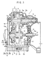
- reference numeral 1 denotes a continuously variable transmission
- reference numeral 2 denotes a transmission case for housing the continuously variable transmission 1.
- the transmission case 2 is divided into a main case 3 and a side case 4 at a mating surface A.
- the main case 3 and the side case 4 are connected at the bottom surface thereof with a control valve body 6 through a common mating surface 5.
- main case 3 is connected at an opposite side of the side case 4 with a torque converter case 7.
- a primary pulley 8 and a secondary pulley 9 are disposed in parallel with each other.
- a primary pulley shaft 10 supporting the primary pulley 8 is connected at an end thereof with a pulley input shaft 12 projected into the torque converter case 7 through a forward and reverse changeover apparatus 11.
- a secondary pulley shaft 13 supporting the secondary pulley 9 is coupled at an end thereof to a reduction drive gear 14 engaged with a final reduction gear unit (not shown) .
- a moving sheave 8a is mounted on the primary pulley shaft 10 at an opposite side of the pulley input shaft 12.
- the moving sheave 8a is moved axially by a hydraulic pressure introduced into a primary pulley actuating chamber 8b.
- a moving sheave 9a is mounted on the secondary pulley shaft 13 at the side of the reduction gear 14.
- the moving sheave 9a is moved axially by a hydraulic pressure introduced into a secondary pulley actuating chamber 9b.
- Both pulleys 8,9 are interconnected with each other by a belt 15.
- the moving sheave 8a is moved axially so as to vary the winding diameter of the belt 15 of the primary pulley 8. At this time, the winding diameter of the secondary pulley 9 varies in a reverse proportion to that of the primary pulley 8.
- An oil pump 16 is disposed between the torque converter case 7 and the main case 3.
- the oil pump 16 is driven by a pump drive shaft 16 which is connected with a pump impeller of a torque converter (not shown). Further, the pulley input shaft 12 is connected with a turbine (not shown) of the torque converter.
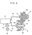
- a pump fluid passage 17 communicating with the oil pump 16 is formed in the main case 3 of the transmission case 2. Further, a line fluid passage 18 and a primary fluid passage 19 are formed in the wall member of the side case 4.
- the line fluid passage 18 communicates with the secondary pulley actuating chamber 9b of the secondary pulley 9 through a fluid passage 13a provided in the secondary pulley shaft 13 and the primary fluid passage 19 communicates with the primary pulley actuating chamber 8b of the secondary pulley 8 through a fluid passage 10a provided in the primary pulley shaft 10.
- the fluid passages 17, 18 and 19 communicate with the control valve body 6 through respective holes (not shown) provided on the mating surface 5.
- the control valve body 6 comprises an upper valve body 6a, a lower valve body 6b and a separator 6c.
- a communicating fluid passage 20 is provided in the upper valve body 6a of the control valve body 6.
- the communicating fluid passage 20 communicates with the pump fluid passage 17 upstream thereof and branches into a plurality of fluid passages.
- the branched communicating fluid passages 20 further communicate with the line fluid passage 18, the primary fluid passage 19 and other fluid passages which are formed in the side case 4, respectively.
- the lower valve body 6b accommodates therein miscellaneous control valves 21 such as a regulator valve for regulating a hydraulic pressure supplied to the line fluid passage 18 so as to maintain a clamping force necessary for torque transmission to the secondary pulley 9, a shift control valve for regulating a hydraulic pressure supplied to the primary fluid passage 19 so as to vary the winding diameters of both pulleys 8,9, and the like.
- miscellaneous control valves 21 such as a regulator valve for regulating a hydraulic pressure supplied to the line fluid passage 18 so as to maintain a clamping force necessary for torque transmission to the secondary pulley 9, a shift control valve for regulating a hydraulic pressure supplied to the primary fluid passage 19 so as to vary the winding diameters of both pulleys 8,9, and the like.
- the regulator valve communicates with the communicating fluid passage 20 connected to the line fluid passage 18 and the shift control valve communicates with the communicating fluid passage 20 connected only to the primary fluid passage 19.
- an O-ring 22 is interposed around the respective holes of the line fluid passage 18 and the primary fluid passage 19 at the mating surface 5. Since when the main case 3 is connected at the bottom surface thereof with the upper valve body 6a, the mating surface 5 between the main case 3 and the upper valve body 6a forms a reference plane, a sink is produced between the side case 4 and the upper valve body 6a when assembled.
- the O-ring 22 is provided for the purpose of absorbing the sink.
- reference numeral 23 denotes an oil strainer and reference numeral 24 denotes an oil pan.
- the primary pulley 8 and the secondary pulley 9 are mounted on the side case 4 of the transmission case 2 and then the side case 4 is fastened to the main case 3 by bolts (not shown).
- the forward and reverse changeover apparatus 11 the oil pump 16 and other surrounding components are accommodated into the main case 3.
- the torque converter case 7 is fastened to the main case 3 by bolts (not shown).
- the oil pump 16 is connected with the pump impeller of the torque converter accommodated in the torque converter case 7 through the oil pump drive shaft 16a.
- control valve body 6 abuts against the common mating surface formed by the bottom surfaces of the main case 3 and the side case 4 and is fastened by bolts.
- the fluid passage 17 on the main case 3 side communicates with the respective fluid passages 18, 19 on the side case 4 side through the communicating fluid passage 20 formed in the upper valve body 6a of the control valve body 6.
- the O-ring 22 serves as absorbing a sink produced between the side case 4 and the upper valve body 6a. Because of this, the mating surface 5 between the both cases 3, 4 and the upper valve body 6a is not necessary to have a tight tolerance in adjusting the height of the bottom surfaces of the cases 3,4, nor machining after assembly is necessary.
- the pump fluid passage 17 provided in the main case 3 communicate with the fluid passages 18, 19 provided in the side case 4 through the communicating fluid passage 20 provided in the control valve body 6, all fluid passages needed for actuating the primary and secondary pulleys or for lubricating miscellaneous transmission components can be accommodated in the wall member of the transmission case 2 without using any special pipe member.
- the assembled continuously variable transmission 1 is connected with the engine (not shown) through the torque converter.
- the pulley input shaft 12 connected to the primary pulley shaft 10 of the primary pulley is spline-fitted to the turbine of the torque converter.
- the oil pump 16 is connected through the oil pump drive shaft 16a with the pump impeller of the torque converter.
- the engine drives the pulley input shaft 12 through the pump impeller and the turbine of the torque converter.
- the oil pump 16 is also driven by the pump impeller to suck working fluid through an oil strainer 23 from an oil pan 24 and to generate a hydraulic pressure downstream of the oil pump 16.
- the hydraulic pressure generated by the oil pump 16 is fed to the fluid passage 20 formed in the upper valve body 6a of the control valve body 6 through the pump fluid passage 17 formed in the main case 3 of the transmission case 2.
- the hydraulic pressure is diverted from the communicating fluid passage 20 into a plurality of fluid passages provided in the upper valve body 6a and is regulated at a predetermined value by the control valves 21 such as a regulator valve, a shift control valve and the like respectively.
- the hydraulic pressure regulated by each control valve 21 is sent to the line fluid passage 18, the primary fluid passage 19 and the like.
- the hydraulic pressure (line pressure) sent to the line fluid passage 18 is supplied to the secondary pulley actuating chamber 9b of the secondary pulley 9 to apply a clamping force necessary for torque transmission to the secondary pulley.
- the hydraulic pressure (primary pressure) sent to the primary fluid passage 19 is supplied to the primary pulley actuating chamber 8b.
- the respective moving sheaves 8a, 9a operate to vary the winding diameter of the respective pulleys 8,9 in reverse proportion, thereby a desired speed ratio is obtained.
- a hydraulic pressure sent to fluid passages not shown in the drawing is used for lubricating the belt 15 or other components.
- the communicating fluid passage 20 for connecting between fluid passages formed in the main case 3 and the side case 4 is integrally formed with the control valve body 6 mounted on the bottom of the transmission case 2, no such dedicated circuit as a lubrication pipe is needed to communicate between the aforesaid fluid passages. Further, since the fluid passages formed in both cases 3, 4 communicate with each other through the control valve body 6, the configuration of the fluid passages formed in both cases 3, 4 can be simplified and the fluid passages become easy to be cast.
Landscapes
- Engineering & Computer Science (AREA)
- General Engineering & Computer Science (AREA)
- Mechanical Engineering (AREA)
- Transmissions By Endless Flexible Members (AREA)
- Control Of Transmission Device (AREA)
- General Details Of Gearings (AREA)
Claims (3)
- Hydraulikkreis eines Automatikgetriebes, das folgendes hat: einen Automatikgetriebe-Mechanismus, ein Getriebegehäuse (2), das in ein Hauptgehäuse (3) und mindestens ein Nebengehäuse (4) unterteilt ist, zur Aufnahme des Automatikgetriebe-Mechanismus darin, einen hydraulischen Betätiger zum Betätigen des Automatikgetriebe-Mechanismus, einen in dem Hauptgehäuse (3) ausgebildeten ersten Fluidkanal (17) zum Durchleiten von Hydraulikdruck, einen in dem Nebengehäuse (4) ausgebildeten zweiten Fluidkanal (18) zum Durchleiten von Hydraulikdruck, und ein Steuerventil (21) zum Steuern des Hydraulikdrucks, dadurch gekennzeichnet, daß er folgendes aufweist:einen Steuerventilkörper (6), der das Steuerventil (21) darin enthält und an einer gemeinsamen Berührungsfläche (5) angebracht ist, die von dem Hauptgehäuse (3) und dem Nebengehäuse (4) so gebildet ist, daß die gemeinsame Berührungsfläche davon geschlossen ist; undeinen in dem Steuerventilkörper (6) ausgebildeten Verbindungskanal (20) zur Verbindung zwischen dem ersten Fluidkanal (17) und dem zweiten Fluidkanal (18).
- Hydraulikkreis nach Anspruch 1, der ferner folgendes aufweist:einen O-Ring (22), der um den zweiten Fluidkanal (18) herum an der Berührungsfläche (5) zwischen dem Nebengehäuse (4) und dem Steuerventilkörper (6) vorgesehen ist.
- Hydraulikkreis nach Anspruch 1, wobei der Verbindungskanal (20) mit dem Steuerventil (21) innerhalb des Steuerventilkörpers (6) in Verbindung steht.
Applications Claiming Priority (2)
| Application Number | Priority Date | Filing Date | Title |
|---|---|---|---|
| JP17775998 | 1998-06-24 | ||
| JP17775998A JP4145390B2 (ja) | 1998-06-24 | 1998-06-24 | 自動変速機の油圧回路構造 |
Publications (3)
| Publication Number | Publication Date |
|---|---|
| EP0967417A2 EP0967417A2 (de) | 1999-12-29 |
| EP0967417A3 EP0967417A3 (de) | 2000-11-02 |
| EP0967417B1 true EP0967417B1 (de) | 2003-05-14 |
Family
ID=16036640
Family Applications (1)
| Application Number | Title | Priority Date | Filing Date |
|---|---|---|---|
| EP99112193A Expired - Lifetime EP0967417B1 (de) | 1998-06-24 | 1999-06-24 | Hydraulikkreislauf für ein Automatikgetriebe |
Country Status (4)
| Country | Link |
|---|---|
| US (1) | US6155138A (de) |
| EP (1) | EP0967417B1 (de) |
| JP (1) | JP4145390B2 (de) |
| DE (1) | DE69907810T2 (de) |
Families Citing this family (10)
| Publication number | Priority date | Publication date | Assignee | Title |
|---|---|---|---|---|
| DE10036256B4 (de) * | 1999-09-09 | 2010-04-15 | Luk Lamellen Und Kupplungsbau Beteiligungs Kg | Getriebe |
| JP4318822B2 (ja) * | 1999-12-24 | 2009-08-26 | 本田技研工業株式会社 | 無段変速機用潤滑油給油装置 |
| JP3461329B2 (ja) * | 2000-07-05 | 2003-10-27 | 本田技研工業株式会社 | 無段変速機の油圧制御装置 |
| DE10255179A1 (de) * | 2002-11-27 | 2004-06-17 | Zf Friedrichshafen Ag | Vorrichtung zur Druckmittelversorgung von Stellmitteln eines automatisierten Schaltgetriebes |
| DE10329214B4 (de) * | 2003-06-28 | 2013-05-29 | Zf Friedrichshafen Ag | Sammelbehälter für Spritzöl |
| DE10342543A1 (de) * | 2003-09-11 | 2005-06-23 | Zf Friedrichshafen Ag | Hydraulisches Schaltgerät |
| US7303495B2 (en) * | 2004-04-27 | 2007-12-04 | General Motors Corporation | Continuously variable transmission case cover |
| DE102005026616A1 (de) * | 2005-06-09 | 2006-12-14 | Zf Friedrichshafen Ag | Stufenloses Automatgetriebe, insbesondere Umschlingungsgetriebe, und Verfahren zur Montage des Variators des Getriebes in das Gehäuse |
| US8042331B2 (en) | 2008-04-01 | 2011-10-25 | GM Global Technology Operations LLC | On-demand hydraulic pump for a transmission and method of operation |
| CN118959551B (zh) * | 2024-10-16 | 2025-02-07 | 坤泰车辆系统(常州)股份有限公司 | 集成式变速箱壳体及加工工艺 |
Citations (1)
| Publication number | Priority date | Publication date | Assignee | Title |
|---|---|---|---|---|
| US4738159A (en) * | 1983-11-14 | 1988-04-19 | Aisin-Warner Ltd. | Four-wheel drive automatic transmission |
Family Cites Families (5)
| Publication number | Priority date | Publication date | Assignee | Title |
|---|---|---|---|---|
| US4210034A (en) * | 1977-08-15 | 1980-07-01 | Younger Gilbert W | Channel plate for automatic transmissions |
| JPS6145145A (ja) * | 1984-08-07 | 1986-03-05 | Aisin Warner Ltd | 自動変速機 |
| JPS6184475A (ja) * | 1984-09-29 | 1986-04-30 | Aisin Warner Ltd | 4輪駆動用自動変速機 |
| JPH02107859A (ja) * | 1988-07-07 | 1990-04-19 | Toyota Motor Corp | 遊星歯車装置 |
| JPH08177890A (ja) * | 1994-12-27 | 1996-07-12 | Nippondenso Co Ltd | 車両用電磁クラッチ制御装置 |
-
1998
- 1998-06-24 JP JP17775998A patent/JP4145390B2/ja not_active Expired - Fee Related
-
1999
- 1999-06-18 US US09/336,478 patent/US6155138A/en not_active Expired - Lifetime
- 1999-06-24 DE DE69907810T patent/DE69907810T2/de not_active Expired - Lifetime
- 1999-06-24 EP EP99112193A patent/EP0967417B1/de not_active Expired - Lifetime
Patent Citations (1)
| Publication number | Priority date | Publication date | Assignee | Title |
|---|---|---|---|---|
| US4738159A (en) * | 1983-11-14 | 1988-04-19 | Aisin-Warner Ltd. | Four-wheel drive automatic transmission |
Also Published As
| Publication number | Publication date |
|---|---|
| DE69907810D1 (de) | 2003-06-18 |
| DE69907810T2 (de) | 2004-04-01 |
| JP4145390B2 (ja) | 2008-09-03 |
| EP0967417A2 (de) | 1999-12-29 |
| US6155138A (en) | 2000-12-05 |
| JP2000009216A (ja) | 2000-01-11 |
| EP0967417A3 (de) | 2000-11-02 |
Similar Documents
| Publication | Publication Date | Title |
|---|---|---|
| CA1252021A (en) | Hydraulic control system for continuously variable transmission | |
| US4753627A (en) | Hydraulic control system for a belt drive continuously-variable speed transmission | |
| US4669336A (en) | Apparatus for controlling line pressure used in V-belt type continuously variable transmission for automobile | |
| US8267830B2 (en) | Combination continuously variable transmission and planetary transmission | |
| US4534243A (en) | Hydraulic control system for a V-belt transmission | |
| US5924539A (en) | Fluid-operated apparatus for operating adjustable constituents of motor vehicles | |
| EP0163290B1 (de) | Stufenlos veränderbares Riemengetriebesystem | |
| US4751859A (en) | Hydraulic control apparatus for hydraulically-operated power transmitting system having continuously variable transmission | |
| US5314385A (en) | System for cooling a starting clutch of a continuously variable transmission | |
| US6155138A (en) | Structure of hydraulic circuit for automatic transmission | |
| EP0117696A1 (de) | Hydraulische Einrichtung für einen stufenlos einstellbaren Antrieb | |
| EP1531291A2 (de) | Stufenlos verstellbares Riemengetriebe | |
| JP3032093B2 (ja) | 自動変速機の油圧制御装置の変速バルブ | |
| US4884997A (en) | V-pulley for belt type continuously variable transmission | |
| US6537176B2 (en) | Arrangement for operating an automotive CVT | |
| US7201684B2 (en) | Speed-changing hydraulic pressure control system for belt-type continuously variable transmission | |
| EP0615079B1 (de) | Schaltsteuerventil für ein stufenlos verstellbares Getriebe | |
| US4828084A (en) | Control circuit for fluid coupling with high-gear clutch | |
| US6503169B2 (en) | Apparatus for controlling a power transmission device | |
| EP0291272A1 (de) | Öldrucksteuerung für ein stufenloses Getriebe | |
| JP2984755B2 (ja) | 無段変速機の変速比制御装置 | |
| US20070117665A1 (en) | Automatic transmission | |
| GB2133095A (en) | Reduction ratio controlling mechanism for a continuously- variable automatic transmission of a vehicle | |
| EP0763675A2 (de) | Gehäusegestaltung eines Automatgetriebes | |
| JPH10141456A (ja) | 無段変速装置の油圧制御回路 |
Legal Events
| Date | Code | Title | Description |
|---|---|---|---|
| PUAI | Public reference made under article 153(3) epc to a published international application that has entered the european phase |
Free format text: ORIGINAL CODE: 0009012 |
|
| AK | Designated contracting states |
Kind code of ref document: A2 Designated state(s): DE GB |
|
| AX | Request for extension of the european patent |
Free format text: AL;LT;LV;MK;RO;SI |
|
| PUAL | Search report despatched |
Free format text: ORIGINAL CODE: 0009013 |
|
| AK | Designated contracting states |
Kind code of ref document: A3 Designated state(s): AT BE CH CY DE DK ES FI FR GB GR IE IT LI LU MC NL PT SE |
|
| AX | Request for extension of the european patent |
Free format text: AL;LT;LV;MK;RO;SI |
|
| 17P | Request for examination filed |
Effective date: 20010405 |
|
| AKX | Designation fees paid |
Free format text: DE GB |
|
| RTI1 | Title (correction) |
Free format text: HYDRAULIC CIRCUIT FOR AUTOMATIC TRANSMISSION |
|
| GRAH | Despatch of communication of intention to grant a patent |
Free format text: ORIGINAL CODE: EPIDOS IGRA |
|
| RTI1 | Title (correction) |
Free format text: HYDRAULIC CIRCUIT FOR AUTOMATIC TRANSMISSION |
|
| GRAH | Despatch of communication of intention to grant a patent |
Free format text: ORIGINAL CODE: EPIDOS IGRA |
|
| GRAA | (expected) grant |
Free format text: ORIGINAL CODE: 0009210 |
|
| AK | Designated contracting states |
Designated state(s): DE GB |
|
| REG | Reference to a national code |
Ref country code: GB Ref legal event code: FG4D |
|
| REF | Corresponds to: |
Ref document number: 69907810 Country of ref document: DE Date of ref document: 20030618 Kind code of ref document: P |
|
| PLBE | No opposition filed within time limit |
Free format text: ORIGINAL CODE: 0009261 |
|
| STAA | Information on the status of an ep patent application or granted ep patent |
Free format text: STATUS: NO OPPOSITION FILED WITHIN TIME LIMIT |
|
| 26N | No opposition filed |
Effective date: 20040217 |
|
| REG | Reference to a national code |
Ref country code: GB Ref legal event code: 746 Effective date: 20040616 |
|
| PGFP | Annual fee paid to national office [announced via postgrant information from national office to epo] |
Ref country code: GB Payment date: 20090624 Year of fee payment: 11 |
|
| GBPC | Gb: european patent ceased through non-payment of renewal fee |
Effective date: 20100624 |
|
| PG25 | Lapsed in a contracting state [announced via postgrant information from national office to epo] |
Ref country code: GB Free format text: LAPSE BECAUSE OF NON-PAYMENT OF DUE FEES Effective date: 20100624 |
|
| PGFP | Annual fee paid to national office [announced via postgrant information from national office to epo] |
Ref country code: DE Payment date: 20150616 Year of fee payment: 17 |
|
| REG | Reference to a national code |
Ref country code: DE Ref legal event code: R119 Ref document number: 69907810 Country of ref document: DE |
|
| PG25 | Lapsed in a contracting state [announced via postgrant information from national office to epo] |
Ref country code: DE Free format text: LAPSE BECAUSE OF NON-PAYMENT OF DUE FEES Effective date: 20170103 |