EP0967427A2 - Rohrverbindung, insbesondere für Kunststoffrohre - Google Patents
Rohrverbindung, insbesondere für Kunststoffrohre Download PDFInfo
- Publication number
- EP0967427A2 EP0967427A2 EP99111921A EP99111921A EP0967427A2 EP 0967427 A2 EP0967427 A2 EP 0967427A2 EP 99111921 A EP99111921 A EP 99111921A EP 99111921 A EP99111921 A EP 99111921A EP 0967427 A2 EP0967427 A2 EP 0967427A2
- Authority
- EP
- European Patent Office
- Prior art keywords
- support sleeve
- pipe connection
- connection according
- grooves
- webs
- Prior art date
- Legal status (The legal status is an assumption and is not a legal conclusion. Google has not performed a legal analysis and makes no representation as to the accuracy of the status listed.)
- Withdrawn
Links
Images
Classifications
-
- F—MECHANICAL ENGINEERING; LIGHTING; HEATING; WEAPONS; BLASTING
- F16—ENGINEERING ELEMENTS AND UNITS; GENERAL MEASURES FOR PRODUCING AND MAINTAINING EFFECTIVE FUNCTIONING OF MACHINES OR INSTALLATIONS; THERMAL INSULATION IN GENERAL
- F16L—PIPES; JOINTS OR FITTINGS FOR PIPES; SUPPORTS FOR PIPES, CABLES OR PROTECTIVE TUBING; MEANS FOR THERMAL INSULATION IN GENERAL
- F16L13/00—Non-disconnectable pipe joints, e.g. soldered, adhesive, or caulked joints
- F16L13/14—Non-disconnectable pipe joints, e.g. soldered, adhesive, or caulked joints made by plastically deforming the material of the pipe, e.g. by flanging, rolling
- F16L13/141—Non-disconnectable pipe joints, e.g. soldered, adhesive, or caulked joints made by plastically deforming the material of the pipe, e.g. by flanging, rolling by crimping or rolling from the outside
- F16L13/143—Non-disconnectable pipe joints, e.g. soldered, adhesive, or caulked joints made by plastically deforming the material of the pipe, e.g. by flanging, rolling by crimping or rolling from the outside with a sealing element placed around the male part before crimping or rolling
-
- F—MECHANICAL ENGINEERING; LIGHTING; HEATING; WEAPONS; BLASTING
- F16—ENGINEERING ELEMENTS AND UNITS; GENERAL MEASURES FOR PRODUCING AND MAINTAINING EFFECTIVE FUNCTIONING OF MACHINES OR INSTALLATIONS; THERMAL INSULATION IN GENERAL
- F16L—PIPES; JOINTS OR FITTINGS FOR PIPES; SUPPORTS FOR PIPES, CABLES OR PROTECTIVE TUBING; MEANS FOR THERMAL INSULATION IN GENERAL
- F16L33/00—Arrangements for connecting hoses to rigid members; Rigid hose-connectors, i.e. single members engaging both hoses
- F16L33/20—Undivided rings, sleeves, or like members contracted on the hose or expanded inside the hose by means of tools; Arrangements using such members
- F16L33/207—Undivided rings, sleeves, or like members contracted on the hose or expanded inside the hose by means of tools; Arrangements using such members only a sleeve being contracted on the hose
- F16L33/2071—Undivided rings, sleeves, or like members contracted on the hose or expanded inside the hose by means of tools; Arrangements using such members only a sleeve being contracted on the hose the sleeve being a separate connecting member
- F16L33/2073—Undivided rings, sleeves, or like members contracted on the hose or expanded inside the hose by means of tools; Arrangements using such members only a sleeve being contracted on the hose the sleeve being a separate connecting member directly connected to the rigid member
- F16L33/2076—Undivided rings, sleeves, or like members contracted on the hose or expanded inside the hose by means of tools; Arrangements using such members only a sleeve being contracted on the hose the sleeve being a separate connecting member directly connected to the rigid member by plastic deformation
-
- F—MECHANICAL ENGINEERING; LIGHTING; HEATING; WEAPONS; BLASTING
- F16—ENGINEERING ELEMENTS AND UNITS; GENERAL MEASURES FOR PRODUCING AND MAINTAINING EFFECTIVE FUNCTIONING OF MACHINES OR INSTALLATIONS; THERMAL INSULATION IN GENERAL
- F16L—PIPES; JOINTS OR FITTINGS FOR PIPES; SUPPORTS FOR PIPES, CABLES OR PROTECTIVE TUBING; MEANS FOR THERMAL INSULATION IN GENERAL
- F16L33/00—Arrangements for connecting hoses to rigid members; Rigid hose-connectors, i.e. single members engaging both hoses
- F16L33/22—Arrangements for connecting hoses to rigid members; Rigid hose-connectors, i.e. single members engaging both hoses with means not mentioned in the preceding groups for gripping the hose between inner and outer parts
- F16L33/225—Arrangements for connecting hoses to rigid members; Rigid hose-connectors, i.e. single members engaging both hoses with means not mentioned in the preceding groups for gripping the hose between inner and outer parts a sleeve being movable axially
Definitions
- the invention relates to a pipe connection, in particular for plastic pipes or composite pipes, for a press connection, with a support sleeve that has a circumferential profile has with webs and grooves, and with a compression sleeve, according to the preamble of Claim 1.
- the at least one profiling of the support sleeve comprises a circumferential recess, which several Has groove webs, a surface envelope extending axially parallel to the support sleeve, which is placed over the radially outer ends of the webs, below which to the Profiling adjacent surface of the support sleeve runs.
- the surface envelope curve has a curvature that is convex or into circumferential surface of the support sleeve runs into it.
- the press sleeve located above the support sleeve compresses so that its material radially inwards over the profiling of the support sleeve is deflected, the material of the plastic tube or the composite tube is in the Profiling sunk into it, on the one hand the individual grooves and webs and on the other the depression caused by the envelope to a superimposed bracket configuration lead, which due to their continuous training a compared to the state of Technology significantly increases holding function and is also self-sealing.
- the continuous curvature of the profiling with respect to the surface envelope leads that cavities after the pressing between the specified pipe and the Support sleeve or their profiling can be avoided.
- the plastic material of the pipe can not later relax in existing cavities, which is the case with the conventional, angular Formation of profiles in support sleeves of pipe connections according to the state of the Technology is regularly the case.
- This relaxation of the material of the tube in cavities leads to the fact that the internal tension of a pipe connection decreases, so that the mechanical Holding force as well as a possible sealing effect suffer from it.
- a web on upper end for example, have a thickness of about 0.7 to 1.0 mm and should each depending on the height of the web or the depth of the adjacent groove at a height of approx. 1.5 to 2.5 mm, for example, should not be less than about 1.4 to about 2.5 mm wide at its base.
- this is just an example of the material is dependent from which the support sleeve is made.
- brass, gunmetal, stainless steel and Even plastics of course, come with other materials to manufacture them Support sleeves of pipe connections into consideration. The same materials come too as manufacturing materials for the compression sleeve of the pipe connection according to the invention in Consideration.
- the lower envelope formed by the grooves which extends axially parallel to the support sleeve, runs below the surface envelope.
- the lower envelope should advantageously also have a curvature that is convex is or extends into the circumferential surface of the support sleeve. This configuration also leads to an improved material flow of the plastic material to be determined Plastic pipes in the profiling.
- the grooves in the longitudinal section of the support sleeve have a rounded profile or are round. This very special type of profiling leads to the fact that here too the formation of cavities can be reliably avoided, so that no relaxation of the plastic material into corresponding cavities can occur later.
- the webs can at least on one side, preferably opposite to the direction of the tube to be fixed with a Have an edge with an included angle of approx. 90 °. It is also possible to use the webs to be provided with tips at their radially outward ends. It turned out to be It is advantageous if the webs have edges that are approximately at an angle of 90 ° have, for example, have an angle in a range from about 70 ° to about 120 °. The angle between the surface of the Web and the radially inward web extension is present.
- a groove for an O-ring connect is provided.
- This groove can of course also be equipped with an O-ring his. It is important to ensure that the pressing tool is effective as far as possible exerts on the compression sleeve only in those areas where under the compression sleeve and under the pipe to be defined is the profiling with features according to the invention.
- the O-ring areas or grooves are to be kept free of increased pressure, so that the O-rings cannot be damaged during the pressing process. Damage the O-rings would have the sealing effect which can be achieved very advantageously by means of these O-rings affect.
- the stop can also have a positioning aid around a pressing tool in a defined position for pressing the compression sleeve on the inventive To be able to start pipe connection.
- a corresponding pressing tool can be used in the form of a pressing tongs or a loop pulling device over a fork-shaped extension on the tool exactly to the positioning aid, for example in the form of a groove, be aligned.
- a further attachment section such as a threaded section, another Support sleeve or the like.
- the pipe connection according to the invention For example, be attached to a distribution block or to extend one Pipe to another pipe.
- a further attachment section can so they are also intended for connecting pipes, also with profiles according to of the invention.
- the support sleeve is at the front end at the end of the tube Abrades the outer circumference so as not to damage the pipes to be pushed open here.
- the rounding on the outer circumference makes it easier to slide on, because on the The outer circumference of the support sleeve has a smaller diameter in the area of the rounding has as the inner diameter of the pipe to be pushed on.
- a position control section can be arranged or provided at the end of the support sleeve.
- This Section can, for example, be provided in the form of a cutout in the stop his. It is also possible to provide a separate, separate ring on the support sleeve, which is interrupted so that on the one hand the ring can act as a spacer and this ring on the other hand has a cutout, so that visually the system of the pipe to the Ring can be checked.
- galvanic isolation can be arranged at the stop-side end of the support sleeve his.
- a groove can be provided, into which one is provided as electrical isolation serving plastic ring can be snapped.
- the situation control section and that In principle, galvanic isolation can be made in one piece.
- the essential features or Advantages of the pipe joint according to the present invention include that the support sleeve with the profiling according to the invention on the one hand during assembly or adjustment of a Tube on the support sleeve causes no damage to the inner circumference of the tube, and on the other hand, after the pressing, a particularly intimate engagement of the material of the tube can be accomplished in the profiling of the support sleeve of the pipe connection. Cavities are largely or completely avoided according to the invention.
- a pipe joint with features according to the invention is generally by Reference number 10 marked.
- the pipe connection 10 has two in principle the same trained support sleeves 12a, 12b, between which a stop 24 is arranged.
- the stop 24 has a groove 26, which serves as a positioning aid, around a pressing tongs or the like can be used as a pressing tool.
- the crimping tool knows one fork-shaped extension, which engages in the groove, the fork-like extension on Tool in conjunction with the groove 26 serves as a guide, so that the pressing tongs are accurate to the millimeter can be brought into position for a pressing process.
- a fixing section 28 is provided, on which, for example, a plastic disc for galvanic isolation of the pipe, for example a plastic-metal-plastic composite pipe (Not shown) to be set against the stop 24 can.
- the support sleeve 14 has three profiles 16 on, which serve for the mechanical fixing of a pipe or a composite pipe. Further 16 respective O-ring grooves with O-rings 22 are provided between the profiles, which are arranged essentially for sealing purposes.
- the lower ends or bottoms of the grooves 18 are also on a corresponding curved curve or a partial circle (see Fig. 3).
- the beginning of the support sleeve which is designated by the reference numeral 32, is rounded, so that the circumference of the support sleeve is reduced in the area of the beginning 32.
- the postponement a pipe is thereby facilitated. Furthermore, this will damage the Inner circumference of the tube when pushing on or pulling off a tube from the Support sleeve 14 avoided in any case.
- the setting area 28 for setting a galvanic isolation and / or a positional control has a groove 28a.
- This one Groove 28a associated web of the fixing section enables snapping, for example a plastic ring, which is then fixed within the groove 28a.
- reference numerals 16 is in the axial direction on her Beginning 16a and its end 16b rounded off at the edges assigned here to also here to counter damage to the inner circumference of the tube when pushing on or pulling it off.
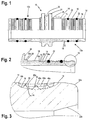
- FIG 3 shows a particularly advantageous type of profiling of the support sleeve 12a, which is provided within the surface 14 of the support sleeve.
- the upper ends of the webs 20 with respect to the surface 14 of the Support sleeve are set back radially inwards.
- the upper ends of the webs 20 for example, along the surface envelope 40a or another surface envelope 40b run.
- the upper ends of the webs 20 run between two surface envelopes, namely the surface envelopes 40a and 40b.
- This measure is for the purpose here performed so that on the edge of the profiling 16 according to FIG. 3, a possible first continuous transition in the deformation and the arrival of the pipe in the Profiling 16 can be accomplished.
- the middle web 20 offset further downward or shorter.
- the pressing area on a press sleeve is provided in this area of the support sleeve become.
- the lower ends or the respective base of the grooves 18 also run on a corresponding one Envelope 40c, wherein the grooves have a rounded shape.
- a conical extension 32b is provided on the inside, which is used to prevent flow noise if possible when for example, water through the pipe and, accordingly, through the pipe connection flows.
- the envelopes 40a, 40b, 40c shown in the figures are of course purely exemplary. It should be borne in mind that the upper ends of the webs or the lower ends of the grooves only come to lie approximately on an envelope curve or in the region of two envelope curves have to.
- the continuity of the shaping of the components of the profiling 16 is essential. the inflowing of the deformed plastic material of a tube and the void-free Filling in the profile should favor.
Landscapes
- Engineering & Computer Science (AREA)
- General Engineering & Computer Science (AREA)
- Mechanical Engineering (AREA)
- Mutual Connection Of Rods And Tubes (AREA)
- Joints That Cut Off Fluids, And Hose Joints (AREA)
Abstract
Description
- Fig. 1
- eine bevorzugte Ausführungsform in einer teils längsschnittlichen Darstellung und einer teils seitenansichtlichen Darstellung wiedergibt;
- Fig. 2
- detaillierter einen Schnitt durch eine Stützhülse der Rohrverbindung gemäß Fig. 1 zeigt; und
- Fig. 3
- einen Ausschnitt gemäß Fig. 2 vergrößert wiedergibt.
Claims (10)
- Rohrverbindung, insbesondere für Kunststoffrohre bzw. Verbundrohre, für eine Preßverbindung, mit einer Stützhülse (12a, 12b), die eine umfängliche Profilierung (16) mit Stegen (20) und Nuten (18) aufweist, und einer Preßhülse, gekennzeichnet durch die folgenden Merkmale:a) die Profilierung umfaßt wenigstens eine umfängliche Vertiefung (16),b) die umfängliche Vertiefung (16) weist mehrere Nuten (18) und Stege (20) auf, undc) eine axial-parallel zur Stützhülse (12a, 12b) erstreckte Oberflächenhüllkurve (40a, 40b), die über die radial außenliegenden Enden der Stege (20) gelegt ist, verläuft unterhalb der an die Profilierung (16) angrenzenden Oberfläche (14) der Stützhülse (12a, 12b).
- Rohrverbindung nach Anspruch 1, dadurch gekennzeichnet, daß die Oberflächenhüllkurve (40a, 40b) eine Krümmung hat, die konvex ist bzw. in die umfängliche Oberfläche (14) in Axialrichtung der Stützhülse hinein verläuft.
- Rohrverbindung nach einem der Ansprüche 1 und 2, dadurch gekennzeichnet, daß die durch die Nuten (18) gebildete untere Hüllkurve (40c), die sich axial-parallel zur Stützhülse erstreckt, unterhalb der Oberflächenhüllkurve (40a, 40b) verläuft.
- Rohrverbindung nach Anspruch 3, dadurch gekennzeichnet, daß die untere Hüllkurve (40c) eine Krümmung hat, die konvex ist bzw. in die umfängliche Oberfläche (14) in Axialrichtung der Stützhülse hinein verläuft.
- Rohrverbindung nach einem der Ansprüche 1 bis 4, dadurch gekennzeichnet, daß die Nuten (18) im Längsschnitt der Stützhülse gerundet bzw. rund oder teilkreisförmig sind.
- Rohrverbindung nach einem der Ansprüche 1 bis 5, dadurch gekennzeichnet, daß die Stege wenigstens auf einer Seite eine Kante mit einem eingeschlossenen Winkel (α) von etwa 80° bis 120°, bevorzugt nahe 90° haben.
- Rohrverbindung nach einem der Ansprüche 1 bis 6, dadurch gekennzeichnet, daß an die Profilierung (16) in Axialrichtung eine Nut für bzw. mit einem O-Ring (22) anschließt.
- Rohrverbindung nach einem der Ansprüche 1 bis 7, dadurch gekennzeichnet, daß in Aufschubrichtung des Rohres am Ende der Stützhülse ein Anschlag (24) vorgesehen ist, wobei der Anschlag (24) bevorzugt einen Positionierhilfebereich (26) zum Ansetzen eines Preßwerkzeuges zum Verpressen der Preßhülse über der Stützhülse (12a) aufweist.
- Rohrverbindung nach einem der Ansprüche 1 bis 14, dadurch gekennzeichnet, daß am Anschlag (24) und/oder an dem dem Anschlag zugeordneten Ende der Stützhülse (12a) ein Lagesichtkontrollabschnitt anordenbar bzw. vorgesehen ist.
- Rohrverbindung nach einem der Ansprüche 1 bis 15, dadurch gekennzeichnet, daß am anschlagseitigen Ende der Stützhülse (12a) eine galvanische Trennung anordenbar (28) bzw. angeordnet ist, wobei bevorzugt der Lagesichtkontrollabschnitt die galvanische Trennung umfaßt.
Applications Claiming Priority (2)
| Application Number | Priority Date | Filing Date | Title |
|---|---|---|---|
| DE1998128141 DE19828141C2 (de) | 1998-06-24 | 1998-06-24 | Rohrverbindung, insbesondere für Kunststoffrohre bzw. Verbundrohre |
| DE19828141 | 1998-06-24 |
Publications (2)
| Publication Number | Publication Date |
|---|---|
| EP0967427A2 true EP0967427A2 (de) | 1999-12-29 |
| EP0967427A3 EP0967427A3 (de) | 2000-01-12 |
Family
ID=7871876
Family Applications (1)
| Application Number | Title | Priority Date | Filing Date |
|---|---|---|---|
| EP99111921A Withdrawn EP0967427A3 (de) | 1998-06-24 | 1999-06-22 | Rohrverbindung, insbesondere für Kunststoffrohre |
Country Status (2)
| Country | Link |
|---|---|
| EP (1) | EP0967427A3 (de) |
| DE (1) | DE19828141C2 (de) |
Cited By (5)
| Publication number | Priority date | Publication date | Assignee | Title |
|---|---|---|---|---|
| EP1705416A1 (de) * | 2005-03-24 | 2006-09-27 | Tiemme Raccorderie S.p.A. | Kupplung für Anlagen, zum Beispiel für eine Heizungs- und Sanitäranlage |
| US11596999B2 (en) | 2019-02-20 | 2023-03-07 | Milwaukee Electric Tool Corporation | PEX expansion tool |
| US11633775B2 (en) | 2019-02-20 | 2023-04-25 | Milwaukee Electric Tool Corporation | PEX expansion tool |
| US11779990B2 (en) | 2021-04-09 | 2023-10-10 | Milwaukee Electric Tool Corporation | Expansion tool |
| US11819902B2 (en) | 2020-11-27 | 2023-11-21 | Milwaukee Electric Tool Corporation | Expansion tool |
Families Citing this family (5)
| Publication number | Priority date | Publication date | Assignee | Title |
|---|---|---|---|---|
| DE19929010C1 (de) * | 1999-06-24 | 2000-11-23 | Kirchner Fraenk Rohr | Kunststofformteil sowie Verbindungsvorrichtung mit diesem |
| DE50004637D1 (de) | 1999-10-28 | 2004-01-15 | Uponor Innovation Ab | Pressfitting für ein Rohr |
| DE102005043238B4 (de) * | 2005-09-09 | 2012-11-08 | Sanha Gmbh & Co. Kg | Rohrverbindung |
| DE102006034101A1 (de) * | 2006-07-20 | 2008-02-07 | VETEC GmbH Verbindungstechnologie für Versorgungssysteme | Hülse und Kombination von Hülse mit Presswerkzeug |
| ES1067747Y (es) * | 2008-04-17 | 2008-09-16 | Multitubo Montaje Y Distribuci | "accesorio para conexion rapida de tubos" |
Family Cites Families (6)
| Publication number | Priority date | Publication date | Assignee | Title |
|---|---|---|---|---|
| FR970583A (fr) * | 1948-08-20 | 1951-01-05 | Embout perfectionné pour raccords | |
| GB1058279A (en) * | 1964-12-30 | 1967-02-08 | Superflexit | End fittings for helically convoluted flexible electric conduits |
| DE1934854U (de) * | 1966-01-04 | 1966-03-17 | Mannesmann Ag | Schlauchkupplung. |
| CH682175A5 (en) * | 1990-11-08 | 1993-07-30 | Geberit Ag | Connection for domestic piping - has fitting to which cylindrical protective socket is releasably fixed, socket covering connection onto which one end of union pipe is pushed |
| DE9116948U1 (de) * | 1991-09-05 | 1994-10-13 | Hewing GmbH, 48607 Ochtrup | Rohrverbindung |
| DE29802519U1 (de) * | 1998-02-14 | 1998-04-09 | Schwarz, Herbert, 79761 Waldshut-Tiengen | Preßnippelverbindung |
-
1998
- 1998-06-24 DE DE1998128141 patent/DE19828141C2/de not_active Expired - Fee Related
-
1999
- 1999-06-22 EP EP99111921A patent/EP0967427A3/de not_active Withdrawn
Cited By (6)
| Publication number | Priority date | Publication date | Assignee | Title |
|---|---|---|---|---|
| EP1705416A1 (de) * | 2005-03-24 | 2006-09-27 | Tiemme Raccorderie S.p.A. | Kupplung für Anlagen, zum Beispiel für eine Heizungs- und Sanitäranlage |
| US11596999B2 (en) | 2019-02-20 | 2023-03-07 | Milwaukee Electric Tool Corporation | PEX expansion tool |
| US11633775B2 (en) | 2019-02-20 | 2023-04-25 | Milwaukee Electric Tool Corporation | PEX expansion tool |
| US11819902B2 (en) | 2020-11-27 | 2023-11-21 | Milwaukee Electric Tool Corporation | Expansion tool |
| US11779990B2 (en) | 2021-04-09 | 2023-10-10 | Milwaukee Electric Tool Corporation | Expansion tool |
| US12390849B2 (en) | 2021-04-09 | 2025-08-19 | Milwaukee Electric Tool Corporation | Expansion tool |
Also Published As
| Publication number | Publication date |
|---|---|
| DE19828141A1 (de) | 1999-12-30 |
| EP0967427A3 (de) | 2000-01-12 |
| DE19828141C2 (de) | 2001-05-17 |
Similar Documents
| Publication | Publication Date | Title |
|---|---|---|
| EP2304301B1 (de) | Anordnung mit einem fitting, einem kraftübertragungselement und einer gleithülse, sowie verfahren zur herstellung einer unlösbaren werkstückverbindung | |
| DE19631574C1 (de) | Rohrverbindung | |
| DE3721577C2 (de) | ||
| DE3435187C2 (de) | Anschlußstücke sowie Verfahren zur Herstellung eines flexiblen Anschlusses für tragbare Pumpen | |
| DE7817369U1 (de) | Schnellkupplung fuer flexible rohre | |
| EP2025988B1 (de) | Fitting für ein Rohr, insbesondere Kunststoffrohr oder Kunststoff-Metall-Verbundrohr | |
| EP2646625B1 (de) | Kupplung, insbesondere für das verbinden von ankerstangen | |
| DE10062227A1 (de) | Verfahren zum Einbauen und Spannen eines freigespannten Zugglieds, insbesondere eines Schrägseils für eine Schrägseilbrücke sowie Verankerungsvorrichtung zum Durchführen des Verfahrens | |
| DE102010038170A1 (de) | Rohrpresskupplungen, insbesondere zur Verpressung von Mehrschichtrohren, sowie Verfahren zum Herstellen einer Rohrpresskupplung | |
| DE19828141C2 (de) | Rohrverbindung, insbesondere für Kunststoffrohre bzw. Verbundrohre | |
| DE3838935A1 (de) | Kupplungsstueck | |
| EP1722146B1 (de) | Verbindungsanordnung für Leitungssystem mit Ringelement | |
| DE4325349C2 (de) | Verbindungsvorrichtung | |
| DE2938006C2 (de) | Vorrichtung zum Verbinden zweier glatter Rohrenden | |
| DE102008004152A1 (de) | Rohrleitung mit einem Anschlussstück | |
| CH682942A5 (de) | Verbindungsteil für eine Pressverbindung. | |
| DE202004000031U1 (de) | Rohrpresskupplung | |
| EP3839316B1 (de) | Kupplungsteil für eine schlauchkupplung | |
| EP1479961B1 (de) | Pressfitting | |
| DE102005033482A1 (de) | Verbindungsvorrichtung | |
| DE10331381A1 (de) | Pressverbindung und Stützhülse für eine Pressverbindung | |
| DE29719536U1 (de) | Preßverbindung | |
| DE69912149T2 (de) | Verbindungsvorrichtung einer metallischen rohrleitung | |
| DE2427560A1 (de) | Radiatorstopfen und verfahren zu seiner herstellung | |
| DE2937193A1 (de) | Rohrverbindungsvorrichtung |
Legal Events
| Date | Code | Title | Description |
|---|---|---|---|
| PUAI | Public reference made under article 153(3) epc to a published international application that has entered the european phase |
Free format text: ORIGINAL CODE: 0009012 |
|
| PUAL | Search report despatched |
Free format text: ORIGINAL CODE: 0009013 |
|
| AK | Designated contracting states |
Kind code of ref document: A2 Designated state(s): AT BE CH DE FR GR IT LI NL |
|
| AX | Request for extension of the european patent |
Free format text: AL;LT;LV;MK;RO;SI |
|
| AK | Designated contracting states |
Kind code of ref document: A3 Designated state(s): AT BE CH CY DE DK ES FI FR GB GR IE IT LI LU MC NL PT SE |
|
| AX | Request for extension of the european patent |
Free format text: AL;LT;LV;MK;RO;SI |
|
| 17P | Request for examination filed |
Effective date: 20000214 |
|
| AKX | Designation fees paid |
Free format text: AT BE CH DE FR GR IT LI NL |
|
| 17Q | First examination report despatched |
Effective date: 20011221 |
|
| STAA | Information on the status of an ep patent application or granted ep patent |
Free format text: STATUS: THE APPLICATION IS DEEMED TO BE WITHDRAWN |
|
| 18D | Application deemed to be withdrawn |
Effective date: 20020702 |