EP0967444A2 - Dispositif pour la ventilation, le refroidissement et /ou le chauffage de locaux - Google Patents
Dispositif pour la ventilation, le refroidissement et /ou le chauffage de locaux Download PDFInfo
- Publication number
- EP0967444A2 EP0967444A2 EP99850111A EP99850111A EP0967444A2 EP 0967444 A2 EP0967444 A2 EP 0967444A2 EP 99850111 A EP99850111 A EP 99850111A EP 99850111 A EP99850111 A EP 99850111A EP 0967444 A2 EP0967444 A2 EP 0967444A2
- Authority
- EP
- European Patent Office
- Prior art keywords
- air
- primary air
- room
- supply
- cooling
- Prior art date
- Legal status (The legal status is an assumption and is not a legal conclusion. Google has not performed a legal analysis and makes no representation as to the accuracy of the status listed.)
- Granted
Links
Images
Classifications
-
- F—MECHANICAL ENGINEERING; LIGHTING; HEATING; WEAPONS; BLASTING
- F24—HEATING; RANGES; VENTILATING
- F24F—AIR-CONDITIONING; AIR-HUMIDIFICATION; VENTILATION; USE OF AIR CURRENTS FOR SCREENING
- F24F1/00—Room units for air-conditioning, e.g. separate or self-contained units or units receiving primary air from a central station
- F24F1/01—Room units for air-conditioning, e.g. separate or self-contained units or units receiving primary air from a central station in which secondary air is induced by injector action of the primary air
-
- F—MECHANICAL ENGINEERING; LIGHTING; HEATING; WEAPONS; BLASTING
- F24—HEATING; RANGES; VENTILATING
- F24F—AIR-CONDITIONING; AIR-HUMIDIFICATION; VENTILATION; USE OF AIR CURRENTS FOR SCREENING
- F24F2221/00—Details or features not otherwise provided for
- F24F2221/14—Details or features not otherwise provided for mounted on the ceiling
Definitions
- the present invention relates to a ceiling mounted device for ventilating rooms and, at the same time, cooling and/or heating the room air, said device including a cooling/heating baffle which has a longitudinal channel for the supply of primary air, a room air cooling/heating coil, a mixing chamber for mixing cooled/heated room air and primary air, means for supplying primary air to the mixing chamber through the medium of an induction effect which serves to suck room air into the device and also to pass said air through the cooling/heating coil, and one or more outlets for a mixture of cooled/heated room air and primary air flowing out from the device essentially horizontally the ceiling of the room.
- a cooling/heating baffle which has a longitudinal channel for the supply of primary air, a room air cooling/heating coil, a mixing chamber for mixing cooled/heated room air and primary air, means for supplying primary air to the mixing chamber through the medium of an induction effect which serves to suck room air into the device and also to pass said air through the cooling/heating coil, and
- Cooling baffles Devices of the aforesaid kind are also referred to as cooling baffles or false ceiling panels. Such devices are known for treating room air and are available in different designs, including designs in which natural ventilation generated by a chimney effect is used instead of primary air, although a common feature of those cooling baffles that use primary air of the aforesaid kind is that they include one or more primary air channels to which primary air can be delivered through a central air-conditioning plant installed either in the building concerned or in the proximity of said building, or which is sucked-in from outside by fans provided to this end, so that the pressure in the primary air channel will always be higher than atmospheric pressure. The primary air is blown into the baffle interior through such devices as nozzles for instance, and the influence of said pressure.
- cooling baffles are lean in energy and do not generate draughts. The level of noise generated is also relatively low.
- An object of the present invention is to provide a device for cooling and/or heating air in larger rooms or in densely populated rooms, so that ventilation and cooling/heating requirements can both be achieved in the individual case in a simple and effective manner with respect to both installation and apparatus, and also in a manner which is competitive and also attractive from a cost aspect.
- the invention is characterised to this end by the features set forth in the accompanying Claims.
- the inventive device includes a baffle in which supply air nozzles are provided for supplying primary air from the primary air channel to the room concerned. These nozzles are disposed in one or more of the baffle walls delimiting the primary air channel.
- the nozzles can be conveniently turned to enable the air to flow in different directions, essentially transversely to the axis about which the nozzle is turned.
- supply air nozzles are arranged immediately outside one or both of said outlet openings in the flow direction of the cooled room air/primary air mixture.
- the device may have different configurations and constructions within the scope of the invention, and may include baffle constructions of an earlier known type combined with supply air nozzles according to the invention, although the device will be described hereinafter with reference to a preferred baffle embodiment.
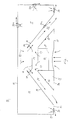
- the baffle 10 has a primary air channel 11 to which primary air 12 is delivered from an external source (not shown).
- the baffle 10 includes an outer casing 13 which delimits the primary air channel 11 outwards, and inner walls 14 which delimit the primary air channel 11 against other parts of the baffle, which include a lower part 15 having a lower plate 16 which forms an outer, lower delimiting wall 17 of the lower part 15 and two outlet channel walls 18 and which together with an upper plate 19 also forms an upper delimiting wall of the lower part 15, said plates preferably being removable.
- the lower part 15 also accommodates one or more cooling/heating coils 20 mounted in coil holders 21 for cooling/heating room air that flows in through openings (not shown) in the lower wall 17, as shown by arrows.
- the mixing chamber 23 is arranged above the lower part 15 and is downwardly delimited by the upper plate 19 of the lower part 15 and laterally by parts of the inner walls 14 bordering on the primary air channel 11.
- nozzles 29 for blowing primary air from the primary air channel 11 into the mixing chamber 23, as shown by arrows, said nozzles being mutually spaced in the longitudinal direction of the baffle 10.
- supply air nozzles 30 Located immediately outside the exit orifice of the outflow channel 22 are supply air nozzles 30, said supply air constituting in practice the primary air that flows in the primary air channel 11, said nozzles being mutually spaced in the casing 13 in the longitudinal direction of the baffle.
- the nozzles 30 are mounted so that they can be turned around a vertical axis and therewith enable supply air through the nozzles 30 to be delivered in different directions, according to local requirements and wishes.
- nozzles 30a of the same kind as the nozzles 30 may be provided at appropriate positions on the baffle 10 adjacent the primary air channel 11. Further nozzles 30b similar to nozzles 30 may be provided in one or in both of the outlet channels 22 with the intention of being mixed with and coacting with the cooled air mixture that flows down from the mixing chamber 23. It lies within the scope of the invention to adapt the number of nozzles 30, 30a and 30b and their positions so as to achieve the best possible comfort in the room, both with respect to ventilation and cooling/heating requirements. In this regard, it may be unsuitable to place nozzles 30 in the lower part of the baffle 10 because of draughts for instance, whereas in other cases a combination of nozzles 30 and 30a or 30b may be preferred.
- supply air from the primary air channel 11 can also be delivered to the room through nozzles 30a on the upper side or one or both of the vertical side walls of the baffle 11, therewith providing necessary ventilation of the room and also generating a multiple of flow patterns around the baffle 10 without requiring the use of separate supply air devices.
- the baffle 10 may also be provided with nozzles 30b in one or both outlet channels 22, so that supply air will be mixed with the cooled air mixture prior to said mixture reaching the outlet opening, and therewith enable the outgoing air stream to be controlled to some extent already in the outlet channels 22.
- the invention enables the cooling/heating requirement of a room to be achieved by dimensioning the length of the baffle/?/, whereas the air requirement can be satisfied with the aid of rotatable nozzles provided in the baffle for supply air from the primary air channel. In many instances, this can result in a shorter length and therewith in smaller dimensions of the cooling/heating baffles and may also replace separate supply air devices, therewith resulting in a more cost-effective solution to the air-conditioning problem for many localities.
Landscapes
- Engineering & Computer Science (AREA)
- Chemical & Material Sciences (AREA)
- Combustion & Propulsion (AREA)
- Mechanical Engineering (AREA)
- General Engineering & Computer Science (AREA)
- Duct Arrangements (AREA)
- Chemical And Physical Treatments For Wood And The Like (AREA)
Applications Claiming Priority (2)
| Application Number | Priority Date | Filing Date | Title |
|---|---|---|---|
| SE9802216A SE9802216L (sv) | 1998-06-23 | 1998-06-23 | Anordning för ventilation och kylning och/eller värmning av lokaler |
| SE9802216 | 1998-06-23 |
Publications (3)
| Publication Number | Publication Date |
|---|---|
| EP0967444A2 true EP0967444A2 (fr) | 1999-12-29 |
| EP0967444A3 EP0967444A3 (fr) | 2000-09-27 |
| EP0967444B1 EP0967444B1 (fr) | 2003-10-15 |
Family
ID=20411794
Family Applications (1)
| Application Number | Title | Priority Date | Filing Date |
|---|---|---|---|
| EP19990850111 Expired - Lifetime EP0967444B1 (fr) | 1998-06-23 | 1999-06-22 | Dispositif pour la ventilation, le refroidissement et /ou le chauffage de locaux |
Country Status (4)
| Country | Link |
|---|---|
| EP (1) | EP0967444B1 (fr) |
| DE (1) | DE69912031T2 (fr) |
| NO (1) | NO320983B1 (fr) |
| SE (1) | SE9802216L (fr) |
Cited By (12)
| Publication number | Priority date | Publication date | Assignee | Title |
|---|---|---|---|---|
| WO2000028263A1 (fr) * | 1998-11-05 | 2000-05-18 | Teknoterm Climate Ab | Appareil de climatisation |
| NL1018216C2 (nl) * | 2001-06-06 | 2002-12-10 | Nijburg Invest B V | Convectorinrichting. |
| EP1319902A1 (fr) * | 2001-12-07 | 2003-06-18 | Fläkt Woods AB | Dispositif de chauffage pour montage au plafond |
| US6715538B2 (en) | 2000-11-24 | 2004-04-06 | Halton Oy | Supply air terminal device |
| US7000688B2 (en) | 2000-11-24 | 2006-02-21 | Halton Oy | Supply air terminal device |
| WO2006018138A1 (fr) * | 2004-08-13 | 2006-02-23 | Ernest Kurz | Procede et dispositif pour aerer et temperer une piece |
| FR2887324A1 (fr) * | 2005-06-15 | 2006-12-22 | J F Cesbron Holding Sa Soc | Installation de climatisation, notamment d'allees s'etendant entre deux gondoles refrigerees |
| WO2009123552A1 (fr) * | 2008-03-31 | 2009-10-08 | Lindab Ab | Procédé et dispositif pour la ventilation d'un espace |
| RU2420696C2 (ru) * | 2006-01-16 | 2011-06-10 | Хальтон Ой | Устройство для подачи воздуха и способ регулирования скорости воздушного потока |
| GB2448079B (en) * | 2007-03-30 | 2012-05-02 | Halton Oy | Supply and exhaust air terminal device |
| EP2035754A4 (fr) * | 2006-06-23 | 2013-05-01 | Veft Aerospace Technology Inc | Controle de courant d'air d'entrainement et dispositifs de filtration |
| EP3951272A1 (fr) * | 2020-08-04 | 2022-02-09 | Enolgas Bonomi S.p.A. | Système de climatisation |
Families Citing this family (1)
| Publication number | Priority date | Publication date | Assignee | Title |
|---|---|---|---|---|
| NO345103B1 (no) * | 2018-10-31 | 2020-09-28 | Trox Auranor Norge As | Kjølebaffel |
Citations (4)
| Publication number | Priority date | Publication date | Assignee | Title |
|---|---|---|---|---|
| GB1011742A (en) | 1961-10-03 | 1965-12-01 | Carrier Corp | Improvements in or relating to an induction type room air conditioning unit |
| GB1274540A (en) | 1969-11-14 | 1972-05-17 | Hendrik Jacobus Spoormaker | Improvements in air conditioning and in air conditioning terminal units therefor |
| GB1468754A (en) | 1973-06-02 | 1977-03-30 | Ltg Lufttechnische Gmbh | Air conditioning apparatus |
| DE3321612A1 (de) | 1983-06-15 | 1984-12-20 | Howaldtswerke-Deutsche Werft Ag Hamburg Und Kiel, 2300 Kiel | Klimageraet |
Family Cites Families (3)
| Publication number | Priority date | Publication date | Assignee | Title |
|---|---|---|---|---|
| DE2033195C3 (de) * | 1970-07-04 | 1981-04-16 | LTG Luftechnische GmbH, 7000 Stuttgart | Luftaustrittseinrichtung für Klimaanlagen |
| SE460923B (sv) * | 1987-04-16 | 1989-12-04 | Farex As | Straalnings- och konvektionselement foer undertaksmontage |
| SE516349C2 (sv) * | 1996-08-26 | 2001-12-17 | Stifab Farex Ab | Anordning för kylning av rumsluft |
-
1998
- 1998-06-23 SE SE9802216A patent/SE9802216L/xx unknown
-
1999
- 1999-06-22 NO NO19993088A patent/NO320983B1/no unknown
- 1999-06-22 EP EP19990850111 patent/EP0967444B1/fr not_active Expired - Lifetime
- 1999-06-22 DE DE1999612031 patent/DE69912031T2/de not_active Expired - Lifetime
Patent Citations (4)
| Publication number | Priority date | Publication date | Assignee | Title |
|---|---|---|---|---|
| GB1011742A (en) | 1961-10-03 | 1965-12-01 | Carrier Corp | Improvements in or relating to an induction type room air conditioning unit |
| GB1274540A (en) | 1969-11-14 | 1972-05-17 | Hendrik Jacobus Spoormaker | Improvements in air conditioning and in air conditioning terminal units therefor |
| GB1468754A (en) | 1973-06-02 | 1977-03-30 | Ltg Lufttechnische Gmbh | Air conditioning apparatus |
| DE3321612A1 (de) | 1983-06-15 | 1984-12-20 | Howaldtswerke-Deutsche Werft Ag Hamburg Und Kiel, 2300 Kiel | Klimageraet |
Cited By (15)
| Publication number | Priority date | Publication date | Assignee | Title |
|---|---|---|---|---|
| WO2000028263A1 (fr) * | 1998-11-05 | 2000-05-18 | Teknoterm Climate Ab | Appareil de climatisation |
| US6520247B2 (en) | 1998-11-05 | 2003-02-18 | Teknoterm Climate Ab | Airconditioning device |
| US6715538B2 (en) | 2000-11-24 | 2004-04-06 | Halton Oy | Supply air terminal device |
| US7000688B2 (en) | 2000-11-24 | 2006-02-21 | Halton Oy | Supply air terminal device |
| NL1018216C2 (nl) * | 2001-06-06 | 2002-12-10 | Nijburg Invest B V | Convectorinrichting. |
| EP1319902A1 (fr) * | 2001-12-07 | 2003-06-18 | Fläkt Woods AB | Dispositif de chauffage pour montage au plafond |
| WO2006018138A1 (fr) * | 2004-08-13 | 2006-02-23 | Ernest Kurz | Procede et dispositif pour aerer et temperer une piece |
| FR2887324A1 (fr) * | 2005-06-15 | 2006-12-22 | J F Cesbron Holding Sa Soc | Installation de climatisation, notamment d'allees s'etendant entre deux gondoles refrigerees |
| RU2420696C2 (ru) * | 2006-01-16 | 2011-06-10 | Хальтон Ой | Устройство для подачи воздуха и способ регулирования скорости воздушного потока |
| US8469783B2 (en) | 2006-01-16 | 2013-06-25 | Halton Oy | Supply air terminal device and method for regulating the airflow rate |
| EP2035754A4 (fr) * | 2006-06-23 | 2013-05-01 | Veft Aerospace Technology Inc | Controle de courant d'air d'entrainement et dispositifs de filtration |
| GB2448079B (en) * | 2007-03-30 | 2012-05-02 | Halton Oy | Supply and exhaust air terminal device |
| WO2009123552A1 (fr) * | 2008-03-31 | 2009-10-08 | Lindab Ab | Procédé et dispositif pour la ventilation d'un espace |
| RU2488749C2 (ru) * | 2008-03-31 | 2013-07-27 | Линдаб Аб | Способ и устройство для вентиляции пространства |
| EP3951272A1 (fr) * | 2020-08-04 | 2022-02-09 | Enolgas Bonomi S.p.A. | Système de climatisation |
Also Published As
| Publication number | Publication date |
|---|---|
| NO320983B1 (no) | 2006-02-20 |
| DE69912031D1 (de) | 2003-11-20 |
| SE9802216L (sv) | 1999-12-24 |
| SE9802216D0 (sv) | 1998-06-23 |
| NO993088D0 (no) | 1999-06-22 |
| EP0967444A3 (fr) | 2000-09-27 |
| DE69912031T2 (de) | 2004-07-22 |
| EP0967444B1 (fr) | 2003-10-15 |
| NO993088L (no) | 1999-12-27 |
Similar Documents
| Publication | Publication Date | Title |
|---|---|---|
| EP0967444B1 (fr) | Dispositif pour la ventilation, le refroidissement et /ou le chauffage de locaux | |
| US6213867B1 (en) | Venturi type air distribution system | |
| US6318113B1 (en) | Personalized air conditioned system | |
| US9885494B2 (en) | System and method for delivering air | |
| US20060211365A1 (en) | Induction diffuser | |
| US4616559A (en) | Variable air diffuser | |
| JP2019105383A (ja) | 空調ユニット | |
| KR20140146109A (ko) | 다중 모드를 갖는 칠드 빔 | |
| FI94800C (fi) | Ilmastointilaite ja ilmastointimenetelmä | |
| EP0967443B1 (fr) | Dispositif pour le refroidissement de l'air d'un local | |
| US7013969B1 (en) | Low noise level HVAC system having displacement with induction | |
| US20060211362A1 (en) | Personalized air conditioning/ displacement ventilation system | |
| US20090124188A1 (en) | Personal distribution terminal | |
| EP1066487A1 (fr) | Dispositif de montage au plafond pour ventilation de locaux et refroidissement ou rechauffage simultane de l'air des locaux | |
| EP1122501A1 (fr) | Dispositif monté au plafond pour ventilation des locaux et refroidissement ou réchauffage simultané de l'air des locaux | |
| JP2010281529A (ja) | 空調ユニット、及び、空調システム | |
| US20120088445A1 (en) | Air distribution unit | |
| US20060211361A1 (en) | Personalized air conditioning displacement ventilation system | |
| JP4615267B2 (ja) | ファン内蔵二重床パネル及びこれを備えた室内空調システム | |
| FI127646B (en) | Supply Unit | |
| KR100822238B1 (ko) | 쾌적 냉난방을 위한 냉·온풍 온도 보정용 에어혼합유닛장치 | |
| KR101236282B1 (ko) | 환기설비의 공기배출장치 | |
| KR200422508Y1 (ko) | 쾌적 냉난방을 위한 냉·온풍 온도 보정용 에어혼합유닛장치 | |
| KR100202280B1 (ko) | 바닥분출 공조 시스템의 급기장치 | |
| FI127579B (en) | incoming air |
Legal Events
| Date | Code | Title | Description |
|---|---|---|---|
| PUAI | Public reference made under article 153(3) epc to a published international application that has entered the european phase |
Free format text: ORIGINAL CODE: 0009012 |
|
| AK | Designated contracting states |
Kind code of ref document: A2 Designated state(s): DE FI FR GB IT NL SE |
|
| AX | Request for extension of the european patent |
Free format text: AL;LT;LV;MK;RO;SI |
|
| PUAL | Search report despatched |
Free format text: ORIGINAL CODE: 0009013 |
|
| AK | Designated contracting states |
Kind code of ref document: A3 Designated state(s): AT BE CH CY DE DK ES FI FR GB GR IE IT LI LU MC NL PT SE |
|
| AX | Request for extension of the european patent |
Free format text: AL;LT;LV;MK;RO;SI |
|
| 17P | Request for examination filed |
Effective date: 20010319 |
|
| AKX | Designation fees paid |
Free format text: DE FI FR GB IT NL SE |
|
| GRAH | Despatch of communication of intention to grant a patent |
Free format text: ORIGINAL CODE: EPIDOS IGRA |
|
| GRAS | Grant fee paid |
Free format text: ORIGINAL CODE: EPIDOSNIGR3 |
|
| GRAA | (expected) grant |
Free format text: ORIGINAL CODE: 0009210 |
|
| AK | Designated contracting states |
Kind code of ref document: B1 Designated state(s): DE FI FR GB IT NL SE |
|
| REG | Reference to a national code |
Ref country code: GB Ref legal event code: FG4D |
|
| REF | Corresponds to: |
Ref document number: 69912031 Country of ref document: DE Date of ref document: 20031120 Kind code of ref document: P |
|
| REG | Reference to a national code |
Ref country code: SE Ref legal event code: TRGR |
|
| ET | Fr: translation filed | ||
| PLBE | No opposition filed within time limit |
Free format text: ORIGINAL CODE: 0009261 |
|
| STAA | Information on the status of an ep patent application or granted ep patent |
Free format text: STATUS: NO OPPOSITION FILED WITHIN TIME LIMIT |
|
| 26N | No opposition filed |
Effective date: 20040716 |
|
| PGFP | Annual fee paid to national office [announced via postgrant information from national office to epo] |
Ref country code: GB Payment date: 20050608 Year of fee payment: 7 |
|
| PG25 | Lapsed in a contracting state [announced via postgrant information from national office to epo] |
Ref country code: GB Free format text: LAPSE BECAUSE OF NON-PAYMENT OF DUE FEES Effective date: 20060622 |
|
| GBPC | Gb: european patent ceased through non-payment of renewal fee |
Effective date: 20060622 |
|
| PGFP | Annual fee paid to national office [announced via postgrant information from national office to epo] |
Ref country code: SE Payment date: 20110622 Year of fee payment: 13 |
|
| PGFP | Annual fee paid to national office [announced via postgrant information from national office to epo] |
Ref country code: NL Payment date: 20110622 Year of fee payment: 13 Ref country code: FI Payment date: 20110617 Year of fee payment: 13 |
|
| PGFP | Annual fee paid to national office [announced via postgrant information from national office to epo] |
Ref country code: IT Payment date: 20110620 Year of fee payment: 13 |
|
| PGFP | Annual fee paid to national office [announced via postgrant information from national office to epo] |
Ref country code: FR Payment date: 20110722 Year of fee payment: 13 |
|
| PGFP | Annual fee paid to national office [announced via postgrant information from national office to epo] |
Ref country code: DE Payment date: 20110621 Year of fee payment: 13 |
|
| REG | Reference to a national code |
Ref country code: NL Ref legal event code: V1 Effective date: 20130101 |
|
| REG | Reference to a national code |
Ref country code: SE Ref legal event code: EUG |
|
| PG25 | Lapsed in a contracting state [announced via postgrant information from national office to epo] |
Ref country code: FI Free format text: LAPSE BECAUSE OF NON-PAYMENT OF DUE FEES Effective date: 20120622 |
|
| PG25 | Lapsed in a contracting state [announced via postgrant information from national office to epo] |
Ref country code: SE Free format text: LAPSE BECAUSE OF NON-PAYMENT OF DUE FEES Effective date: 20120623 Ref country code: IT Free format text: LAPSE BECAUSE OF NON-PAYMENT OF DUE FEES Effective date: 20120622 |
|
| REG | Reference to a national code |
Ref country code: FR Ref legal event code: ST Effective date: 20130228 |
|
| REG | Reference to a national code |
Ref country code: DE Ref legal event code: R119 Ref document number: 69912031 Country of ref document: DE Effective date: 20130101 |
|
| PG25 | Lapsed in a contracting state [announced via postgrant information from national office to epo] |
Ref country code: NL Free format text: LAPSE BECAUSE OF NON-PAYMENT OF DUE FEES Effective date: 20130101 Ref country code: DE Free format text: LAPSE BECAUSE OF NON-PAYMENT OF DUE FEES Effective date: 20130101 Ref country code: FR Free format text: LAPSE BECAUSE OF NON-PAYMENT OF DUE FEES Effective date: 20120702 |