EP0967509A2 - Eine multifocale Linse - Google Patents
Eine multifocale Linse Download PDFInfo
- Publication number
- EP0967509A2 EP0967509A2 EP99304619A EP99304619A EP0967509A2 EP 0967509 A2 EP0967509 A2 EP 0967509A2 EP 99304619 A EP99304619 A EP 99304619A EP 99304619 A EP99304619 A EP 99304619A EP 0967509 A2 EP0967509 A2 EP 0967509A2
- Authority
- EP
- European Patent Office
- Prior art keywords
- lens
- far
- substrate
- near vision
- vision zones
- Prior art date
- Legal status (The legal status is an assumption and is not a legal conclusion. Google has not performed a legal analysis and makes no representation as to the accuracy of the status listed.)
- Granted
Links
Images


Classifications
-
- G—PHYSICS
- G02—OPTICS
- G02C—SPECTACLES; SUNGLASSES OR GOGGLES INSOFAR AS THEY HAVE THE SAME FEATURES AS SPECTACLES; CONTACT LENSES
- G02C7/00—Optical parts
- G02C7/02—Lenses; Lens systems ; Methods of designing lenses
- G02C7/06—Lenses; Lens systems ; Methods of designing lenses bifocal; multifocal ; progressive
- G02C7/061—Spectacle lenses with progressively varying focal power
- G02C7/063—Shape of the progressive surface
-
- G—PHYSICS
- G02—OPTICS
- G02B—OPTICAL ELEMENTS, SYSTEMS OR APPARATUS
- G02B3/00—Simple or compound lenses
- G02B3/10—Bifocal lenses; Multifocal lenses
-
- G—PHYSICS
- G02—OPTICS
- G02C—SPECTACLES; SUNGLASSES OR GOGGLES INSOFAR AS THEY HAVE THE SAME FEATURES AS SPECTACLES; CONTACT LENSES
- G02C7/00—Optical parts
- G02C7/02—Lenses; Lens systems ; Methods of designing lenses
- G02C7/06—Lenses; Lens systems ; Methods of designing lenses bifocal; multifocal ; progressive
- G02C7/061—Spectacle lenses with progressively varying focal power
- G02C7/068—Special properties achieved by the combination of the front and back surfaces
-
- G—PHYSICS
- G02—OPTICS
- G02C—SPECTACLES; SUNGLASSES OR GOGGLES INSOFAR AS THEY HAVE THE SAME FEATURES AS SPECTACLES; CONTACT LENSES
- G02C2202/00—Generic optical aspects applicable to one or more of the subgroups of G02C7/00
- G02C2202/20—Diffractive and Fresnel lenses or lens portions
Definitions
- the present invention relates generally to multifocal lenses, and in particular to multifocal lenses combining the properties of progressive addition lenses (PAL) and diffractive lenses.
- PAL progressive addition lenses
- Multifocal lenses are known and widely used, being prescribed for those requiring different dioptric powers for distance and reading vision. This condition is called "presbyopia”. It mostly appears when one gets older and age renders it difficult for the eye (if not impossible) to focus on near and distant objects. This condition may be relieved by prescribing one pair of lenses for distance vision and another for reading vision. A single pair of either bifocal or multifocal lenses can replace both of these pairs of lenses.
- the most common multifocal lens is the so-called "progressive addition lens” or PAL.
- This lens has a far vision zone located at the top of the lens, and a near vision zone located at the bottom of the lens, the far and near vision zones being connected by an intermediate transition region.
- this intermediate transition region called “corridor”
- focus changes continuously from the focus at the far vision zone to that of the near vision zone.
- the locations of the far and near vision zones are dictated by the prescribed parameters of the optical powers required for an individual's "distance” and “reading” visions which define the lens' addition.
- a PAL is characterized by the gradual change of its optical power from the top of the lens to the bottom.
- both the upper, far vision zone and the lower, near vision zone of the PAL should be as wide as possible, to enable the wearer to read comfortably, without having to move his head sideways to follow the text.
- large far and near vision zones result in a shorter intermediate transition region in between them, i.e. corridor, making this region less usable.
- PALs are generally of two designs, so-called “hard” and “soft” designs, depending on the distance between the far and near vision zones, i.e., the length of the corridor, which ranges typically between 16 and 24mm.
- the "hard” design is characterized by a relatively sharp transition region, as compared to that of the "soft” design. Such a sharp transition region induces large distortions on either side of the corridor.
- the "soft” design sacrifices the widths of far and near vision zones in favor of a more gradual transition with less distortion.
- the main principles of PALs of "hard” and “soft” designs are illustrated in Figs. 1 and 2, respectively.
- Fig. 1 shows an image I 1 of a pattern of equidistant, vertical lines L , which is obtained through a PAL with "hard" power variations. It is evident, that the optical power at a bottom region R B of the lens, i.e. in the near vision zone which produces a relatively larger magnification for the reading vision, is larger than the power at a top region R T which is used for distance vision. Additionally, the line separation ⁇ L B in the bottom region R B is wider than the line separation ⁇ L T in the top region R T . With a progressive continuous power profile, top portions L T of the imaged lines L join smoothly with bottom portions L B , so that they must bend in the intermediate region, or corridor, of the lens.
- the line bending effect produces image distortion, for example, similar to that one would observe through a cylindrical lens with an axis at 45 0 .
- the distortion is minimal along the central vertical line L 0 , and increases towards periphery regions at both sides of the central vertical line L 0 .
- the width of the intermediate region between the far and near vision zones of the lens is determined by an area in the lens where distortion remains below a predefined threshold, normally 0.5 diopter cylinder.
- a predefined threshold normally 0.5 diopter cylinder.
- Fig. 2 illustrates an image I 2 of a pattern of equidistant, vertical lines L , which is obtained through'a PAL of a "soft" design with much more gradual progression. It is seen that the line bending is less pronounced here, as compared to that of the hard PAL shown in Fig. 1. Moreover, the distortion is lower, and a corridor is longer and wider. The height of a near vision zone, through which a lower region R B of the image I 2 is obtained, and which is defined by the region where line-portions L B are straight and equidistant, is nevertheless much shorter. The same may be said about a far vision zone through which the upper region R T of the image I 2 is obtained.
- Multifocal contact lenses follow markedly different design considerations.
- Known contact lenses with more than a single power are, generally, of three types: simultaneous vision bifocal lenses, simultaneous vision multifocal lenses and diffractive lenses based on the Fresnel zone plate concept.
- a simultaneous vision bifocal lens is constructed from two or more concentric rings with alternating powers corresponding to distance and reading visions. The wearer of such a bifocal lens observes a scene through both powers simultaneously, relying on a curious psychological effect to overcome the inevitable blurring of the observed scene. When observing a distant scene, the eye focuses in accordance with the distance vision power, while the near vision induces a foggy or hazy background, which, for many individuals, is not objectionable.
- a simultaneous multifocal contact lens has a progressive radial change in power.
- Diffractive lenses in general, employ a different effect, as compared to the refractive lenses.
- Diffraction is a phenomenon that occurs when an electromagnetic wave, such as light, encounters an obstacle and propagates non-linearly. This ability to "bend" a part of a light beam is the basic property used to realize any diffractive lens.
- Diffractive lenses are lightweight substitutes for the conventional refractive lenses used in monochromatic applications.
- the diffractive contact lens based on the Fresnel zone plate, it can perform just like a refractive lens.
- the Fresnel zone plate comprises a circular concentric phase grating PG with a pitch varying quadratically with the distance from the center C 0 .
- Fig. 4 illustrates a profile 10 of a phase grating utilizing the Fresnel zone plate.
- the profile 10 is designed such that a single diffraction order, for example "-1", survives. It is understood that with the grating pitch becoming smaller with the radial distance, the diffraction angle, or beam bending effect, grows proportionally, and an incident collimated light beam becomes focused on a point, which is the typical behavior of a lens. This is the physical principle on which the diffractive contact lens relies to achieve its aim.
- a multifocal lens can be produced from the diffractive lens by forming a radial grating having several orders, usually two or three, on a substrate shaped like a normal spherical or toric lens.
- a tri-focal diffractive lens is disclosed, for example, in U.S. Patent No. 5,760,871.
- Fig. 5 illustrates the main operational principles of a multifocal diffractive lens 12 comprising a radial grating 14 formed on a spherical substrate 16.
- the lens 12 focuses images from infinity 18A , from a middle distance 18B and from a reading distance 18C onto an imaging surface, i.e., a retinal surface 20 of the eye.
- the zero order has the power of the lens substrate 16 , which would be observed in the absence of the grating 14.
- Positive (+1) and negative (-1) diffraction orders produce high and low powers of the lens 12 , respectively.
- the power difference between the positive and the negative orders is referred to as the power addition of the lens.
- a diffractive lens The advantages of a diffractive lens are associated with the following.
- the selection of correct design parameters of the diffractive lens allows for minimizing its chromatic aberrations, which are present in any refractive lens. Indeed, the angle of refraction and diffraction angle change with the light wavelength in opposite directions, and the combination of these two parameters produces a near achromatic lens.
- Other advantages of the diffractive lens are the absence of distortion and the availability of the entire lens area for far, intermediate and near vision.
- the diffraction lens suffers from drawbacks associated with the fact that only a small percentage of light (about 30-40%) is available for each focusing range, and with the unavoidable image blurring.
- a technique disclosed in the above patent is aimed at increasing the percentage of incident light generated through each diffraction order.
- the diffraction grating has a specific pattern (e.g., trapezoidal protrusions and trapezoidal recesses) with the phase difference between light passing through protrusions and recesses (optical height) substantially less than the half of an average optical wavelength viewed with the lens.
- the major feature of the present invention is to provide such a lens that is characterized by large focusing areas for far and near vision, whereby, for example, the wearer may read without having to move his head from side to side along the lines of a given text.
- a further feature of the present invention is to provide such a lens that has a smooth transition between the far and near vision focusing areas, so that the wearer may take advantage of the intermediate focusing region.
- a multifocal lens having far and near vision zones comprising:
- the modulation is formed on the convex surface of the PAL substrate which, preferably, is of a soft design.
- the modulation is of a kind producing diffraction orders, for example, a phase grating.
- the modulation produces an optical power addition to the optical power of the substrate. This optical power addition is maximal within the intermediate transition region and decreases gradually towards the far and near vision zones of the substrate.
- Figs. 1 and 2 schematically illustrate the main principles of PALs with “hard” and “soft” power variations, respectively.
- Figs. 3 and 4 illustrate, respectively, the Fresnel zone plate and a diffraction grating utilizing the same.
- Fig. 5 illustrates the tri-focal diffractive lens.
- the lens 22 comprises a substrate 24 and a diffraction grating 26 (constituting a modulation) formed on a convex surface 24A of the substrate 24.
- the substrate 24 is designed like a soft PAL having a prescribed power addition, while the diffraction grating 26 has locally variable power addition, as will be described more specifically further below.
- the diffraction grating 26 is a phase grating producing three diffraction orders, for example, "-1", "0" and "+1".
- a grating period distribution of the diffraction grating 26 is carefully designed such that the power of the grating 26 vanishes at a top part 28 and a lower part 30 of the PAL substrate 24 .
- An intermediate transition region 32 or corridor, is located between the top and the lower parts 28 and 30 of the PAL substrate 24.
- the lens 22 is manufactured by the known technology of holographic optical elements (HOE). Diffractive lenses in the form of holographic optical elements (HOE) have been developed. The diffraction pattern of such a lens is designed to produce a specific optical effect. HOE elements are normally designed by computer, and are produced by etching, electron beam machining and other advanced technologies.
- the PAL substrate 24 could be of a "hard” design. Additionally, although not specifically shown, the modulation 26 could be formed on a concave surface of the substrate 24 .
- FIG. 7 Three graphs, G 1 , G 2 and G 3 , illustrate the power distribution of the lens 22 while focusing, respectively, three diffraction orders "+1", “0” and “-1" (positive, zero and negative orders) along the lens between the far and near vision zones 28 and 30 .
- Each graph presents the dependence of the dioptric power of the lens 22 ( X -axis) in the intermediate region 32 with the position along the height of this region ( Y -axis).
- Y -axis the illustration in Fig. 7 is qualitative and is therefore not drawn to any specific scale. For example, the full scale along the Y -axis may be 40mm.
- the range of the positions along the height of the corridor 32 starts from the origin Y 1 which borders with the lower part 30 , and continues up to the edges of the top part 28 , i.e., the coordinate Y 2 .
- Graphs G 1 , G 2 and G 3 look like S -shaped hysteresis curves rotated by 90° to vertical position, with all three curves converging together and joining in a left upper part 34 and right lower part 36 of Fig.7.
- the zero order does not deflect light beyond the normal refraction of the lens material, but rather behaves like the original "soft"' design PAL substrate 24 .
- the power of the grating vanishes at the top part 28 of the PAL substrate 24 such that the diffractive power of the grating 26 there is equal to zero, and, as seen in Fig. 7, the three orders are identical.
- the wearer of the multifocal lens 22 looks through the far vision zone 28 , where there is zero power addition produced by the grating, he enjoys the advantage of all the light available.
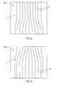
- Fig. 8 illustrates an image IM T of upper portions L T of equidistant vertical lines L observed through the far vision zone 28 of the lens 22.
- Fig. 8 illustrates an image IM T of upper portions L T of equidistant vertical lines L observed through the far vision zone 28 of the lens 22.
- focusing on the "-1" order has the effect of increasing the far vision zone 28 with a major part of the transition region 32 , and without sacrificing the transition region.
- the power of the grating vanishes at the bottom part 30 of the PAL substrate 24 , as shown in Fig. 7, the three orders are identical, thereby causing the multifocal lens 22 to behave like the original "soft" design PAL substrate 24 .
- the diffraction grating 26 increases the near vision zone 30 by adding a major part of the corridor 32 to the near vision zone 30 .
- Fig. 9 illustrating an image IM B of lower portions L B of equidistant vertical lines L observed through the near vision zone 30 of the lens 22 .
- the separation of the three orders decreases gradually to zero at the bottom part 30, which is the reading zone, where all three orders are again the same.
- FIG. 6 the profile of the corridor 32 of the lens 22 is shown.
- the larger curvature of the lens 22 within the bottom part 30 signifies a higher optical power in this region.
- the modulation of the surface of the lens 22 producing a phase grating is more pronounced in the transition region 32 , where it brings about a separation between the three orders "-1", "0" and "+1", as shown in Fig. 7. It should be noted that the diffraction effect diminishes towards the edges 28 and 30 , where the multifocal lens 22 behaves like an ordinary PAL.
- the combination of a PAL with a diffraction grating may be regarded as a carrier with a modulation.
- the carrier is the refractive substrate 24
- the modulation is implemented as the diffraction grating 26 .
- the distribution of refractive power in the substrate 24 could be achieved not only by a suitable surface profile but also by other means.
- the surface may be spherical, as shown in Fig. 5, with the refractive power distribution achieved using gradient index materials.
- Such a lens with refractive index profile increasing from the top to bottom will produce a power increase in the same direction.
- the optical power variation of the diffraction grating 26 is smaller than the power addition of the prescribed PAL 24 .
- efficiency, ergonomics and even aesthetic aspects should be considered to define various parameters of the diffraction grating, such as pitch, shape, relative location on the PAL substrate, etc.
- the advantages of the present invention are self-evident. Indeed, all three diffraction orders exhibit soft low distortion profiles.
- the lens is characterized by relatively wide far and near vision zones, as compared to those of a conventional PAL. All the light energy is available over the sizable portion of both the far and near vision zones. Diffraction haze (image blurring) occurs only along the transition zone (corridor), and is less prominent, as compared to pure diffraction lenses. This is due to the fact that the power differential between the different diffraction orders is smaller.
- the diffraction grating parameters on either side of the corridor can vary towards the reduction of the distortion that remains there even with a "soft" profile.
- the change of the power of the diffraction grating with the light wavelength compensates for the change induced by the refractive power of the PAL substrate, thereby reducing the chromatic aberration of the entire combination.
- the modulation 26 may be formed on either surface of the PAL substrate 24 .
- the modulation may be of any suitable profile, provided it is capable of producing the desired effect, i.e., diffraction orders.
Landscapes
- Physics & Mathematics (AREA)
- Health & Medical Sciences (AREA)
- Ophthalmology & Optometry (AREA)
- General Physics & Mathematics (AREA)
- Optics & Photonics (AREA)
- General Health & Medical Sciences (AREA)
- Eyeglasses (AREA)
- Diffracting Gratings Or Hologram Optical Elements (AREA)
- Materials For Medical Uses (AREA)
Applications Claiming Priority (2)
| Application Number | Priority Date | Filing Date | Title |
|---|---|---|---|
| IL12499198 | 1998-06-18 | ||
| IL12499198A IL124991A (en) | 1998-06-18 | 1998-06-18 | Multifocal lens combining the advantages of progressive addition lenses and diffractive lenses |
Publications (3)
| Publication Number | Publication Date |
|---|---|
| EP0967509A2 true EP0967509A2 (de) | 1999-12-29 |
| EP0967509A3 EP0967509A3 (de) | 2000-11-08 |
| EP0967509B1 EP0967509B1 (de) | 2010-02-24 |
Family
ID=11071648
Family Applications (1)
| Application Number | Title | Priority Date | Filing Date |
|---|---|---|---|
| EP99304619A Expired - Lifetime EP0967509B1 (de) | 1998-06-18 | 1999-06-14 | Eine multifocale Linse |
Country Status (6)
| Country | Link |
|---|---|
| US (1) | US6270220B1 (de) |
| EP (1) | EP0967509B1 (de) |
| AT (1) | ATE459020T1 (de) |
| DE (1) | DE69942049D1 (de) |
| DK (1) | DK0967509T3 (de) |
| IL (1) | IL124991A (de) |
Cited By (1)
| Publication number | Priority date | Publication date | Assignee | Title |
|---|---|---|---|---|
| GB2423828A (en) * | 2005-03-03 | 2006-09-06 | Peter John Charles Spurgeon | Magnifying device with areas of different magnification |
Families Citing this family (63)
| Publication number | Priority date | Publication date | Assignee | Title |
|---|---|---|---|---|
| US6871951B2 (en) * | 2000-06-23 | 2005-03-29 | E-Vision, Llc | Electro-optic lens with integrated components |
| US6857741B2 (en) | 2002-01-16 | 2005-02-22 | E-Vision, Llc | Electro-active multi-focal spectacle lens |
| US6986579B2 (en) | 1999-07-02 | 2006-01-17 | E-Vision, Llc | Method of manufacturing an electro-active lens |
| US6619799B1 (en) | 1999-07-02 | 2003-09-16 | E-Vision, Llc | Optical lens system with electro-active lens having alterably different focal lengths |
| US7023594B2 (en) | 2000-06-23 | 2006-04-04 | E-Vision, Llc | Electro-optic lens with integrated components |
| US7404636B2 (en) | 1999-07-02 | 2008-07-29 | E-Vision, Llc | Electro-active spectacle employing modal liquid crystal lenses |
| US7604349B2 (en) | 1999-07-02 | 2009-10-20 | E-Vision, Llc | Static progressive surface region in optical communication with a dynamic optic |
| US7775660B2 (en) | 1999-07-02 | 2010-08-17 | E-Vision Llc | Electro-active ophthalmic lens having an optical power blending region |
| US7290875B2 (en) | 2004-11-02 | 2007-11-06 | Blum Ronald D | Electro-active spectacles and method of fabricating same |
| US7988286B2 (en) | 1999-07-02 | 2011-08-02 | E-Vision Llc | Static progressive surface region in optical communication with a dynamic optic |
| US7896916B2 (en) | 2002-11-29 | 2011-03-01 | Amo Groningen B.V. | Multifocal ophthalmic lens |
| SE0203564D0 (sv) | 2002-11-29 | 2002-11-29 | Pharmacia Groningen Bv | Multifocal opthalmic lens |
| US6951391B2 (en) * | 2003-06-16 | 2005-10-04 | Apollo Optical Systems Llc | Bifocal multiorder diffractive lenses for vision correction |
| AR045370A1 (es) | 2003-08-15 | 2005-10-26 | E Vision Llc | Sistema de lente electro-activo |
| US7025456B2 (en) * | 2004-08-20 | 2006-04-11 | Apollo Optical Systems, Llc | Diffractive lenses for vision correction |
| US7156516B2 (en) * | 2004-08-20 | 2007-01-02 | Apollo Optical Systems Llc | Diffractive lenses for vision correction |
| US20060066808A1 (en) * | 2004-09-27 | 2006-03-30 | Blum Ronald D | Ophthalmic lenses incorporating a diffractive element |
| US7506983B2 (en) | 2004-09-30 | 2009-03-24 | The Hong Kong Polytechnic University | Method of optical treatment |
| EP2527908B1 (de) * | 2004-10-25 | 2019-03-20 | Johnson & Johnson Surgical Vision, Inc. | Ophthalmische Linse mit mehreren diffraktiven Zonen |
| US7922326B2 (en) | 2005-10-25 | 2011-04-12 | Abbott Medical Optics Inc. | Ophthalmic lens with multiple phase plates |
| US9801709B2 (en) | 2004-11-02 | 2017-10-31 | E-Vision Smart Optics, Inc. | Electro-active intraocular lenses |
| MX2007005198A (es) | 2004-11-02 | 2007-06-20 | E Vision Llc | Anteojos electro-activos y metodos para fabricarlos. |
| US8915588B2 (en) | 2004-11-02 | 2014-12-23 | E-Vision Smart Optics, Inc. | Eyewear including a heads up display |
| US8778022B2 (en) | 2004-11-02 | 2014-07-15 | E-Vision Smart Optics Inc. | Electro-active intraocular lenses |
| US20080273166A1 (en) | 2007-05-04 | 2008-11-06 | William Kokonaski | Electronic eyeglass frame |
| US7656509B2 (en) | 2006-05-24 | 2010-02-02 | Pixeloptics, Inc. | Optical rangefinder for an electro-active lens |
| JP2009541793A (ja) | 2006-06-23 | 2009-11-26 | ピクセルオプティクス, インコーポレイテッド | 電気活性眼鏡レンズ用の電子アダプタ |
| AR064985A1 (es) | 2007-01-22 | 2009-05-06 | E Vision Llc | Lente electroactivo flexible |
| MX2009008829A (es) | 2007-02-23 | 2011-10-28 | Pixeloptics Inc | Apertura dinamica oftalmica. |
| US7883207B2 (en) | 2007-12-14 | 2011-02-08 | Pixeloptics, Inc. | Refractive-diffractive multifocal lens |
| US20080273169A1 (en) | 2007-03-29 | 2008-11-06 | Blum Ronald D | Multifocal Lens Having a Progressive Optical Power Region and a Discontinuity |
| CA2679977A1 (en) | 2007-03-07 | 2008-09-18 | Pixeloptics, Inc. | Multifocal lens having a progressive optical power region and a discontinuity |
| WO2008121975A2 (en) * | 2007-03-29 | 2008-10-09 | Pixeloptics, Inc. | Multifocal lens having a progressive optical power region and a discontinuity |
| US12572035B2 (en) | 2007-05-04 | 2026-03-10 | E-Vision Optics, Llc | Moisture-resistant eye wear |
| US11061252B2 (en) | 2007-05-04 | 2021-07-13 | E-Vision, Llc | Hinge for electronic spectacles |
| US10613355B2 (en) | 2007-05-04 | 2020-04-07 | E-Vision, Llc | Moisture-resistant eye wear |
| US7654667B2 (en) * | 2007-05-10 | 2010-02-02 | Pixeloptics, Inc. | Progressive addition lens operating in combination with a multi-order diffractive optic |
| US8317321B2 (en) | 2007-07-03 | 2012-11-27 | Pixeloptics, Inc. | Multifocal lens with a diffractive optical power region |
| MX2010006042A (es) | 2007-12-14 | 2010-06-25 | Pixeloptics Inc | Lente compuesto multifocal de multiples capas. |
| US7926941B2 (en) * | 2007-12-14 | 2011-04-19 | Pixeloptics Inc. | Multiple layer multifocal composite lens |
| US7744215B2 (en) * | 2007-12-25 | 2010-06-29 | Pixeloptics, Inc. | Multiple layer multifocal composite lens |
| BRPI0908992A2 (pt) | 2008-03-18 | 2015-11-24 | Pixeloptics Inc | dispositivo ótico eletro-ativo avançado |
| US8154804B2 (en) | 2008-03-25 | 2012-04-10 | E-Vision Smart Optics, Inc. | Electro-optic lenses for correction of higher order aberrations |
| US9039762B2 (en) * | 2010-03-23 | 2015-05-26 | Novartis Ag | Accommodating intraocular lens using trapezoidal phase shift |
| US12436411B2 (en) | 2010-07-02 | 2025-10-07 | E-Vision Optics, Llc | Moisture-resistant eye wear |
| US12510773B2 (en) | 2011-02-11 | 2025-12-30 | E-Vision Optics, Llc | Moisture-resistant eye wear |
| JP5872785B2 (ja) * | 2011-04-07 | 2016-03-01 | イーエイチエス レンズ フィリピン インク | 累進屈折力レンズの設計方法 |
| CA3167661A1 (en) | 2012-01-06 | 2013-07-11 | E-Vision Smart Optics, Inc. | Eyewear docking station and electronic module |
| EP2890287B1 (de) | 2012-08-31 | 2020-10-14 | Amo Groningen B.V. | Linse mit mehreren ringen sowie systeme und verfahren für erweiterte fokustiefe |
| DE102014004381B4 (de) | 2014-03-26 | 2023-08-10 | Rodenstock Gmbh | Verbesserte ophthalmische Linse zur Presbyopie-Korrektion sowie Verfahren zum Herstellen und Vorrichtung |
| EP3413840A1 (de) | 2016-02-09 | 2018-12-19 | AMO Groningen B.V. | Gleitsichtintraokularlinse und verfahren zur verwendung und herstellung |
| US10599006B2 (en) | 2016-04-12 | 2020-03-24 | E-Vision Smart Optics, Inc. | Electro-active lenses with raised resistive bridges |
| ES2861520T3 (es) | 2016-04-12 | 2021-10-06 | E Vision Smart Optics Inc | Lentes electroactivas con puentes resistivos elevados |
| EP3595584A1 (de) | 2017-03-17 | 2020-01-22 | AMO Groningen B.V. | Diffraktive intraokularlinsen für erweiterten sichtbereich |
| US11523897B2 (en) | 2017-06-23 | 2022-12-13 | Amo Groningen B.V. | Intraocular lenses for presbyopia treatment |
| EP4487816A3 (de) | 2017-06-28 | 2025-03-12 | Amo Groningen B.V. | Diffraktive linsen und zugehörige intraokularlinsen zur behandlung von presbyopie |
| EP3639084B1 (de) | 2017-06-28 | 2025-01-01 | Amo Groningen B.V. | Erweiterte reichweite und verwandte intraokularlinsen zur behandlung von presbyopie |
| US11327210B2 (en) | 2017-06-30 | 2022-05-10 | Amo Groningen B.V. | Non-repeating echelettes and related intraocular lenses for presbyopia treatment |
| US12204178B2 (en) | 2018-12-06 | 2025-01-21 | Amo Groningen B.V. | Diffractive lenses for presbyopia treatment |
| CA3166308A1 (en) | 2019-12-30 | 2021-07-08 | Amo Groningen B.V. | Lenses having diffractive profiles with irregular width for vision treatment |
| TWI741902B (zh) * | 2020-12-07 | 2021-10-01 | 春秋光學股份有限公司 | 用於減緩或預防近視進展之鏡片 |
| CN113253482B (zh) * | 2021-06-01 | 2022-05-13 | 苏州科技大学 | 一种渐进多焦点眼镜片两段式子午线设计方法 |
| EP4390517A1 (de) * | 2022-12-23 | 2024-06-26 | Carl Zeiss Vision International GmbH | Brillenglasdesigndaten und verfahren zur herstellung eines brillenglases |
Family Cites Families (7)
| Publication number | Priority date | Publication date | Assignee | Title |
|---|---|---|---|---|
| DE2814678C2 (de) * | 1978-04-05 | 1982-07-29 | Hermann Prof. Dr.med. 4400 Münster Gernet | Sehhilfe bei einseitiger Aphakie oder Pseudophakie |
| US4338005A (en) * | 1978-12-18 | 1982-07-06 | Cohen Allen L | Multifocal phase place |
| DE3377535D1 (en) * | 1982-10-27 | 1988-09-01 | Pilkington Plc | Bifocal contact lens comprising a plurality of concentric zones |
| US4881804A (en) * | 1987-11-12 | 1989-11-21 | Cohen Allen L | Multifocal phase plate with a pure refractive portion |
| JP2756670B2 (ja) * | 1987-11-30 | 1998-05-25 | 旭光学工業株式会社 | 累進多焦点眼鏡レンズ |
| US5760871A (en) * | 1993-01-06 | 1998-06-02 | Holo-Or Ltd. | Diffractive multi-focal lens |
| US5682223A (en) * | 1995-05-04 | 1997-10-28 | Johnson & Johnson Vision Products, Inc. | Multifocal lens designs with intermediate optical powers |
-
1998
- 1998-06-18 IL IL12499198A patent/IL124991A/en not_active IP Right Cessation
-
1999
- 1999-06-14 DK DK99304619.2T patent/DK0967509T3/da active
- 1999-06-14 DE DE69942049T patent/DE69942049D1/de not_active Expired - Fee Related
- 1999-06-14 AT AT99304619T patent/ATE459020T1/de not_active IP Right Cessation
- 1999-06-14 EP EP99304619A patent/EP0967509B1/de not_active Expired - Lifetime
- 1999-06-16 US US09/334,067 patent/US6270220B1/en not_active Expired - Fee Related
Cited By (1)
| Publication number | Priority date | Publication date | Assignee | Title |
|---|---|---|---|---|
| GB2423828A (en) * | 2005-03-03 | 2006-09-06 | Peter John Charles Spurgeon | Magnifying device with areas of different magnification |
Also Published As
| Publication number | Publication date |
|---|---|
| DE69942049D1 (de) | 2010-04-08 |
| EP0967509B1 (de) | 2010-02-24 |
| EP0967509A3 (de) | 2000-11-08 |
| ATE459020T1 (de) | 2010-03-15 |
| DK0967509T3 (da) | 2010-05-31 |
| IL124991A0 (en) | 1999-01-26 |
| US6270220B1 (en) | 2001-08-07 |
| IL124991A (en) | 2002-12-01 |
Similar Documents
| Publication | Publication Date | Title |
|---|---|---|
| US6270220B1 (en) | Multifocal lens | |
| US12164181B2 (en) | Diffractive trifocal lens | |
| US4338005A (en) | Multifocal phase place | |
| US5760871A (en) | Diffractive multi-focal lens | |
| US9329407B2 (en) | Extended depth field optics with variable pupil diameter | |
| CN116636956B (zh) | 多焦点人工晶状体 | |
| GB2058391A (en) | Ophthalmic lens having a progressively variable focal power | |
| JP2017509024A (ja) | 老眼補正のための改良された眼科用レンズ | |
| JP4618656B2 (ja) | 累進多焦点レンズシリーズ | |
| JP4380887B2 (ja) | 累進多焦点レンズ | |
| JP2899296B2 (ja) | 多焦点位相板の製造方法 | |
| CN109143426A (zh) | 一种位相编码菲涅尔透镜 | |
| JP4450480B2 (ja) | 累進多焦点レンズシリーズ | |
| IL104316A (en) | Composite diffractive lens | |
| CN208999588U (zh) | 一种用于成像的位相编码菲涅尔透镜 | |
| HK40097410B (zh) | 多焦点人工晶状体 | |
| HK40097410A (zh) | 多焦点人工晶状体 | |
| HK40054118B (zh) | 多焦点人工晶状体 | |
| JP2004309588A (ja) | 累進多焦点レンズ及びその設計方法 |
Legal Events
| Date | Code | Title | Description |
|---|---|---|---|
| PUAI | Public reference made under article 153(3) epc to a published international application that has entered the european phase |
Free format text: ORIGINAL CODE: 0009012 |
|
| AK | Designated contracting states |
Kind code of ref document: A2 Designated state(s): AT BE CH CY DE DK ES FI FR GB GR IE IT LI |
|
| AX | Request for extension of the european patent |
Free format text: AL;LT;LV;MK;RO;SI |
|
| PUAL | Search report despatched |
Free format text: ORIGINAL CODE: 0009013 |
|
| AK | Designated contracting states |
Kind code of ref document: A3 Designated state(s): AT BE CH CY DE DK ES FI FR GB GR IE IT LI LU MC NL PT SE |
|
| AX | Request for extension of the european patent |
Free format text: AL;LT;LV;MK;RO;SI |
|
| RIC1 | Information provided on ipc code assigned before grant |
Free format text: 7G 02C 7/02 A, 7G 02C 7/04 B |
|
| 17P | Request for examination filed |
Effective date: 20010427 |
|
| AKX | Designation fees paid | ||
| REG | Reference to a national code |
Ref country code: DE Ref legal event code: 8566 |
|
| RBV | Designated contracting states (corrected) |
Designated state(s): AT BE CH CY DE DK ES FI FR GB GR IE IT LI |
|
| 17Q | First examination report despatched |
Effective date: 20030626 |
|
| RAP1 | Party data changed (applicant data changed or rights of an application transferred) |
Owner name: Y.M.S. INVESTMENT LTD. |
|
| RBV | Designated contracting states (corrected) |
Designated state(s): AT BE CH DE DK ES FI FR GB IE IT LI NL SE |
|
| GRAP | Despatch of communication of intention to grant a patent |
Free format text: ORIGINAL CODE: EPIDOSNIGR1 |
|
| GRAS | Grant fee paid |
Free format text: ORIGINAL CODE: EPIDOSNIGR3 |
|
| GRAA | (expected) grant |
Free format text: ORIGINAL CODE: 0009210 |
|
| AK | Designated contracting states |
Kind code of ref document: B1 Designated state(s): AT BE CH DE DK ES FI FR GB IE IT LI NL SE |
|
| REG | Reference to a national code |
Ref country code: GB Ref legal event code: FG4D |
|
| REG | Reference to a national code |
Ref country code: CH Ref legal event code: EP |
|
| REG | Reference to a national code |
Ref country code: IE Ref legal event code: FG4D |
|
| REF | Corresponds to: |
Ref document number: 69942049 Country of ref document: DE Date of ref document: 20100408 Kind code of ref document: P |
|
| REG | Reference to a national code |
Ref country code: DK Ref legal event code: T3 |
|
| REG | Reference to a national code |
Ref country code: NL Ref legal event code: VDEP Effective date: 20100224 |
|
| PG25 | Lapsed in a contracting state [announced via postgrant information from national office to epo] |
Ref country code: FI Free format text: LAPSE BECAUSE OF FAILURE TO SUBMIT A TRANSLATION OF THE DESCRIPTION OR TO PAY THE FEE WITHIN THE PRESCRIBED TIME-LIMIT Effective date: 20100224 Ref country code: AT Free format text: LAPSE BECAUSE OF FAILURE TO SUBMIT A TRANSLATION OF THE DESCRIPTION OR TO PAY THE FEE WITHIN THE PRESCRIBED TIME-LIMIT Effective date: 20100224 |
|
| PG25 | Lapsed in a contracting state [announced via postgrant information from national office to epo] |
Ref country code: SE Free format text: LAPSE BECAUSE OF FAILURE TO SUBMIT A TRANSLATION OF THE DESCRIPTION OR TO PAY THE FEE WITHIN THE PRESCRIBED TIME-LIMIT Effective date: 20100224 Ref country code: NL Free format text: LAPSE BECAUSE OF FAILURE TO SUBMIT A TRANSLATION OF THE DESCRIPTION OR TO PAY THE FEE WITHIN THE PRESCRIBED TIME-LIMIT Effective date: 20100224 Ref country code: ES Free format text: LAPSE BECAUSE OF FAILURE TO SUBMIT A TRANSLATION OF THE DESCRIPTION OR TO PAY THE FEE WITHIN THE PRESCRIBED TIME-LIMIT Effective date: 20100604 Ref country code: BE Free format text: LAPSE BECAUSE OF FAILURE TO SUBMIT A TRANSLATION OF THE DESCRIPTION OR TO PAY THE FEE WITHIN THE PRESCRIBED TIME-LIMIT Effective date: 20100224 |
|
| PLBE | No opposition filed within time limit |
Free format text: ORIGINAL CODE: 0009261 |
|
| STAA | Information on the status of an ep patent application or granted ep patent |
Free format text: STATUS: NO OPPOSITION FILED WITHIN TIME LIMIT |
|
| REG | Reference to a national code |
Ref country code: CH Ref legal event code: PL Ref country code: DK Ref legal event code: EBP |
|
| 26N | No opposition filed |
Effective date: 20101125 |
|
| GBPC | Gb: european patent ceased through non-payment of renewal fee |
Effective date: 20100614 |
|
| REG | Reference to a national code |
Ref country code: FR Ref legal event code: ST Effective date: 20110228 |
|
| PG25 | Lapsed in a contracting state [announced via postgrant information from national office to epo] |
Ref country code: IT Free format text: LAPSE BECAUSE OF FAILURE TO SUBMIT A TRANSLATION OF THE DESCRIPTION OR TO PAY THE FEE WITHIN THE PRESCRIBED TIME-LIMIT Effective date: 20100224 |
|
| PG25 | Lapsed in a contracting state [announced via postgrant information from national office to epo] |
Ref country code: IE Free format text: LAPSE BECAUSE OF NON-PAYMENT OF DUE FEES Effective date: 20100614 Ref country code: LI Free format text: LAPSE BECAUSE OF NON-PAYMENT OF DUE FEES Effective date: 20100630 Ref country code: CH Free format text: LAPSE BECAUSE OF NON-PAYMENT OF DUE FEES Effective date: 20100630 Ref country code: DE Free format text: LAPSE BECAUSE OF NON-PAYMENT OF DUE FEES Effective date: 20110101 |
|
| PG25 | Lapsed in a contracting state [announced via postgrant information from national office to epo] |
Ref country code: FR Free format text: LAPSE BECAUSE OF NON-PAYMENT OF DUE FEES Effective date: 20100630 |
|
| PG25 | Lapsed in a contracting state [announced via postgrant information from national office to epo] |
Ref country code: GB Free format text: LAPSE BECAUSE OF NON-PAYMENT OF DUE FEES Effective date: 20100614 |
|
| PG25 | Lapsed in a contracting state [announced via postgrant information from national office to epo] |
Ref country code: DK Free format text: LAPSE BECAUSE OF NON-PAYMENT OF DUE FEES Effective date: 20100630 |